Table of Contents
Advertisement
Quick Links
Download this manual
See also:
Instruction Manual
Advertisement
Table of Contents

Subscribe to Our Youtube Channel
Related Manuals for REED R5820


Summary of Contents for REED R5820
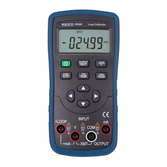
- Page 1 LOOP Calibrator User Manual - 1 -...
- Page 2 WARRANTY Our company warrants to the original purchaser that each product it manufactures will be free from defects in material and workmanship under normal use and service for a period of one year from date of purchase. Our company’s warranty does not apply to fuses, test leads or any product which, in our company’ s opinion, has been misused, altered, or damaged by accident or abnormal conditions of operation or handling.
- Page 3 four inches of excelsior or similar shock-absorbing material. CLAIM FOR DAMAGE IN SHIPMENT TO ORIGINAL PURCHASER The instrument should be thoroughly inspected immediately upon original delivery to purchaser. All material in the container should be checked against the enclosed packing list. The manufacturer will not be responsible for shortages against the packing sheet unless notified immediately.
-
Page 4: Table Of Contents
INDEX P a g e Safety Information………………………………………………………………………………………………………… 1 Instrument Panel Layout and Functions……………………………………………………………………………… 2 Instrument Maintenance………………………………………………………………………………………………… 3 Power-on/off of Instrument……………………………………………………………………………………………… 4 Output from Instrument……………………………………………………………………………………………………5 Instrument Measurement…………………………………………………………………………………………………7 Setting Function………………………………………………………………………………………………………… 10 Performance Index……………………………………………………………………………………………………… 11 Calibration…………………………………………………………………………………………………………………12 Notice of the Manual………………………………………………………………………………………………………15 - 4 -... -
Page 5: Safety Information
• Never apply more than 30V between any two terminals, or between any terminal and earth ground. Section One Safety Information Caution To ensure the safety operation, the following signs are used only as • No one is allowed to remove the split case of the Instrument except specified in this operation instruction:... -
Page 6: Instrument Panel Layout And Functions
Section Two Instrument Panel Layout and Functions Display Area mA%/unit select key Power switch key Output/in Single put switch step/auto-sw itch key & 100% 25% single setting/aut step setting/ o-ramp auto-ramp start key πθ τ υInput Output value digit Input/outp terminal lustration of LCD Display Area - 6 -... -
Page 7: Instrument Maintenance
: These symbols denote the turn-on or turn-off ON、 OFF of any input / output signals. :These symbols denote the high and low-speed auto-ramp, auto-step ramp. Section Three Instrument Maintenance This section provides some basic maintenance procedures. Repair, calibration, and servicing not covered in this manual must be performed by qualified OUTPUT :... - Page 8 This Instrument is powered by two AA batteries (IEC LR6). Warning To avoid electrical shock or personal injury: Remove Test Leads from the Instrument before opening the battery door. Close and latch the Battery Cover before using the meter. Note The new and old Batteries cannot be mixed.
-
Page 9: Power-On/Off Of Instrument
Reinstall the cover; carried out. Reinstall the meter’s protector. Note To ensure correct operation of the Instrument, it is recommended to turn off the power pausing 5 seconds and then restart the Instrument. Automatic Power-off The factory default setting is that the Instrument will cut off the power automatically if no operation applied to the Instrument within 15 minutes. - Page 10 Instrument is in an output state; Function Display Setting Range Press the key〔mA%/V〕, to select the output to be Operation Operation set in ‘mA’or %, and then the unit mA or mA% 00.000~22.000 00.000 mA appears, in which 0% denotes 4mA; 100% denotes 20 mA 20mA;...
- Page 11 Repress the key 〔25%/RAMP〕 so as to exit the step change the type of the output ramp, which finds current output. itself in the lower left of the LCD. The type appears with ‘ ’ , in proper order. These ’、...
-
Page 12: Instrument Measurement
earth ground. Any voltage more than 30V will not only do INPUT +LOOP damage to the Instrument, but also lead to possible personal injury. Caution +mA- OUTPUT • During the operation, do not apply a voltage or current exceeding the measuring range to the input terminal, which will cause possible damage to the Instrument. - Page 13 The refreshing rate of measurement result is twice Measuring DC Current Insert one end of the test lead into the mA jack of every second. And the LCD displays ‘OL’ if the the Instrument (INPUT)terminal and connect the measured value exceeds the measuring range. other end to the output of the user’s device as shown in Figure 5-3: Measuring DC Voltage...
-
Page 14: Setting Function
INPUT INPUT +LOOP +LOOP +mA- OUTPUT +mA- OUTPUT Transmitter Figure 5-4 Providing 24V Power Supply for Measuring Loop Section Seven Setting Function Current Fulfilling of the following operation will change the Insert the test lead into the +LOOP and mA input auto-power-off function of the Instrument: jacks of the input terminal (INPUT)... -
Page 15: Performance Index
Section Eight Performance Index Output Performance Index (applicable to temperature range from 18℃ to 28℃, within one year after calibration) Output Range Output Range Resolution Accuracy Remark ±0.05% set value 0.000~22.000mA 20mA 0.001mA Max. load 1KΩat 20mA. ±4uA Max. load 1KΩat 20mA. Simu-transmitter(absorption ±0.05% set value 0.000~-22.000mA... - Page 16 Input Range Output Range Resolution Accuracy Remark -0.200~28.000V Voltage ±0.02% reading±2mV Input resistance about 1MΩ -1.000~22.000mA Current 20mA 0.001mA ±0.02% reading±4uA resistance about 20Ω 0.000~22.000mA Loop Current 20mA 0.001mA ±0.02% reading±4uA providing 24V loop power General Specifications Power supply 2 1.5V alkaline batteries(LR6) Battery life about 400mA /3V under the condition of 10mA with 1kΩ...
-
Page 17: Calibration
Calibration: In order to keep the designed accuracy of this Instrument, it is recommendable to calibrate your calibrator once a year. The following example shows the use of recommended standard equipment to perform the calibration. Caution Usage:Never apply more than the max. permitted voltage to the input of the calibrator, otherwise the overvoltage will lead to possible damage to the input section. - Page 18 is recommendable to use 2 1.5V(LR6)batteries. When the output stabilized , press the key〔τ〕/〔υ〕 and the key 〔π〕/〔θ〕to adjust the calibrator to a Operating Output Calibration Operating calibration in order of items and calibration value in identity with the reading of the digit meter; points listed in Table 10-2: Press the key 〔...
- Page 19 Set the output of standard source as the value given 00.000mA in Table 10-3 and when the output stabilized , press DCA/20mA FS : 19.000mA the 〔100%/START〕 key, and the LCD displays ‘SAVE ’, denoting that the calibrated point has 00.000V DCV/28V been stored;...
-
Page 20: Notice Of The Manual
Figure 10-3 Press the key〔STEP/AUTO〕and the LCD displays ‘CAL FS’ , and repeat the operation of steps 4. Section Ten Notice of the Manual The present operation instruction is subject to change without notice; The content of the operation instruction is regarded as correct.
Need help?
Do you have a question about the R5820 and is the answer not in the manual?
Questions and answers