
Related Manuals for REED R5600


Summary of Contents for REED R5600
- Page 1 Black R5600 Model Pantone 534 Blue - 100/80/30/5 Digital Insulation Tester Pantone 485 Red - 10/100/100/5 Pantone 123 Yellow - 0/27/100/ Instruction Manual reedinstruments 1.800.561.8187 information@itm.com www. .com...
-
Page 2: Table Of Contents
Yellow - 0/27/100/0 Pantone 123 Yellow Red - 10/100/100/5 Pantone 485 Red Yellow - 0/27/100/0 Pantone 123 Yellow For service on this or any other REED product, contact REED Instruments at info@reedinstruments.com. Blue - 100/80/30/5 Pantone 534 Blue reedinstruments Black... -
Page 3: Safety
Pantone 534 Blue Yellow - 0/27/100/0 Pantone 123 Yellow CE Comply with EN-61010-1 Red - 10/100/100/5 Pantone 485 Red For service on this or any other REED product, contact REED Instruments Yellow - 0/27/100/0 Pantone 123 Yellow at info@reedinstruments.com. Blue - 100/80/30/5 Pantone 534 Blue... -
Page 4: Specifications
Specifications General Specifications Environment conditions • Installation Categories II • Pollution Degree 2 • Altitude up to 2000 meters • Indoor use only • Relatively humidity 80% max. • Operation Ambient 0~40ºC Maintenance & Cleaning • Repairs or servicing not covered in this manual should only be performed by qualified personnel. • Periodically wipe the case with a dry cloth. Do not use abrasives or solvents on this instruments. Display: Large LCD with dual display Measurement Range: 200Ω, 200kΩ, 200MΩ/250V, 200MΩ/500V, 2000MΩ/1000V, 750V/ACV, 1000V/DCV. Sampling Rate: 2.5 times per second. Zero Adjustment: Automatic adjustment. Over Range Indicator: Number 1 of highest digit is displayed. -
Page 5: Electrical
Electrical Specifications Accuracies are specified by: ±(…% of reading +…digits) at 23ºC±5ºC,below 80% RH. OHMS Max. open Overload Range Resolution Accuracy Circuit Voltage Protection 200Ω 0.1Ω 4.5V +(1%+2) 250Vrms 200kΩ 0.1kΩ 3.0V Continuity Beeper Operation Max.open Overload Range Resolution Resistance Circuit Voltage Protection •))) 0.1Ω Resistance≤40Ω 4.5V 250Vrms Short circuit current: ≤200mA DC Voltage Input... -
Page 6: Meter Description
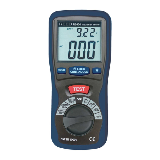
Meter Description 1 — Digital Display 2 — Data Hold Button 3 — Lock Button 4 — Backlight Button 5 — Test Button 6 — Rotary Function switch 7 — VΩ Jack 8 — COM input jack 9 — Pothook 10 — Battery Cover Operating Instructions How to connect test leads 1. On MΩ Range: Connect the red test lead into the “VΩ” terminal and the black lead into the “COM” terminal. 2. On 200Ω and ACV Range: Connect the red test lead into the “VΩ” terminal and the black lead into terminal “COM” How to check the test leads Blue - 100/80/30/5 Pantone 534 Blue Set the range select switch to the 200Ω range. With the tip and alligator Yellow - 0/27/100/0 Pantone 123 Yellow clip of the test leads connected, the indicator should read 00.0Ω. When Red - 10/100/100/5 Pantone 485 Red... -
Page 7: How To Check The Test Leads
Battery Replacement 1. When the battery power is not sufficient the LCD will display 2. Replacement of 6 new batteries, type 1.5V size “AA” is required. 3. Once replaced be sure to reinstall the battery cover and the four screws before operating. Measurements Insulation Resistance Measurements Measurements at 200MΩ/250V This is the voltage used for the majority of insulation resistance tests on normal installation requirements. To measure insulation resistance, press the test button to turn on the tester. The LCD will display the insulation resistance. Section VII indicated that subdivision of large installations might be necessary because of the large number of parallel insulation resistance. In such a case, an installation may be divided into sections, each being separately tested. Each section must have at least fifty outlets, an outlet being a switch, socket, lighting point etc. A switched socket counts as one outlet. The minimum accept- able insulation resistance is 1MΩ. For a large installation, the capacitance of the insulation will be high, and it will take longer for it to become charged by the direct testing voltage. Be careful not to take a reading until there is a steady reading, indicating that the charging process is complete. Note: The charge stored in the insulation will be discharged automatically when the test button is released. Be careful not to turn the range switch knob while the test button is pressed, or the instrument will be damaged. -
Page 8: Low Resistance Measurements
Note: Make sure that the circuit under does not include components Which will be damaged by the 1000V applied. Many normal components of an installation are likely to be damaged if tested at 1000V. Examples are power factor correction capacitors, low voltage mineral insulated cables, electronic light dimmers, electronic ballasts and starters for fluorescent lamps etc… Lock Power on Feature For hands free operation a lock power on feature is incorporated in the press to test button. Set the LOCK button to lock test voltage, pressing it again will turn the tester off. Low Resistance (Continuity) Measurements 1. Set the range switch to 200Ω •))) Position 2. Connect the red test lead to the V Ω terminal and back to the COM terminal. 3. Connect the tips of the test leads to both ends of the circuit under test. Read resistance in Ω on the LCD. 4. When the impedance on circuit is below approximately 40Ω. It will indicate by a continuous beeper. AC/DC Voltage Measurements 1. Set the range switch to ACV or DCV position 2. Connect red test lead to “V Ω” terminal and black test lead to terminal “COM”. 3. Connect test prods of test leads IN PARALLEL to the circuit being measured. 4. Read the voltage value on LCD. Blue - 100/80/30/5 Pantone 534 Blue Yellow - 0/27/100/0 Pantone 123 Yellow... -
Page 9: Power Tool & Small Appliances
Power Tools & Small Appliances This test would also apply to other similar equipment that has a line cord. For double insulated power tools, the megohmmeter lead shown (See graphic on page 8) connected to the housing would be connected to some metal part of the tool (ie: chuck, blade). Note: The switch of the device must be in the “ON” position and the main power should be disconnected. -
Page 10: Cables
Yellow - 0/27/100/0 Pantone 123 Yellow Red - 10/100/100/5 Pantone 485 Red Yellow - 0/27/100/0 Pantone 123 Yellow For service on this or any other REED product, contact REED Instruments at info@reedinstruments.com. Blue - 100/80/30/5 Pantone 534 Blue reedinstruments Black... - Page 11 Notes _________________________________________ ________________________________________________ ________________________________________________ ________________________________________________ ________________________________________________ ________________________________________________ ________________________________________________ ________________________________________________ ________________________________________________ ________________________________________________ ________________________________________________ ________________________________________________ ________________________________________________ ________________________________________________ ________________________________________________ ________________________________________________ Blue - 100/80/30/5 Pantone 534 Blue Yellow - 0/27/100/0 Pantone 123 Yellow ________________________________________________ Red - 10/100/100/5 Pantone 485 Red Yellow - 0/27/100/0 ________________________________________________ Pantone 123 Yellow Blue - 100/80/30/5 Pantone 534 Blue...
- Page 12 ________________________________________________ ________________________________________________ ________________________________________________ ________________________________________________ ________________________________________________ ________________________________________________ ________________________________________________ ________________________________________________ ________________________________________________ ________________________________________________ ________________________________________________ ________________________________________________ ________________________________________________ ________________________________________________ ________________________________________________ ________________________________________________ Blue - 100/80/30/5 Pantone 534 Blue Yellow - 0/27/100/0 Pantone 123 Yellow ________________________________________________ Red - 10/100/100/5 Pantone 485 Red Yellow - 0/27/100/0 ________________________________________________ Pantone 123 Yellow Blue - 100/80/30/5 Pantone 534 Blue reedinstruments...
Need help?
Do you have a question about the R5600 and is the answer not in the manual?
Questions and answers