
Subscribe to Our Youtube Channel
Related Manuals for REED R5004


Summary of Contents for REED R5004
- Page 1 Black R5004 Model Pantone 534 Blue - 100/80/30/5 Phase & Motor Rotation Pantone 485 Red - 10/100/100/5 Pantone 123 Yellow - 0/27/100/ Tester Instruction Manual reedinstruments...
-
Page 2: Table Of Contents
Table of Contents Safety .................... 3 Features ..................3 Specifications ................3-4 Instrument Description ..............5 Operating Instructions ..............5-7 Determining the Rotary Field Direction......... 5 Phase Indication Table ..............6 Non-contact Rotary Field Indication ..........6 Motor Test Requirements ............7 Determining the Motor Connection .......... -
Page 3: Safety
Safety • Protective equipment must be used to prevent shock and injury • Use of this instrument in a manner not specified by the manufacturer may impair safety features/protection provided by the equipment • Avoid working alone • Damaged leads must be replaced •... -
Page 4: Operating Voltage
Protection type: IP40 Protection levels: CATIII600V, CATIV300V Standards: DIN VDE 0411, IEC 61010 DIN, VDE 0413-7, IEC 61557-7/EN 61557-7 Operating voltage: Multiple connections: 40 to 600V AC between phases; Single connection: 120 to 400V AC between phases Power supply: 9V alkaline, IEC 6LR61 Power consumption: Max 20 mA Battery life:... -
Page 5: Instrument Description
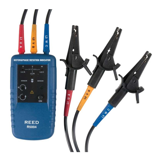
Instrument Description Test lead input jack L1, L2, L3 indicators Clockwise rotation LCD indicator Counter-clockwise rotation LCD indicator ON/OFF button ON/OFF indicator Orientation symbol Operating Instructions Determining the Rotary Field Direction Connect one end of the test leads to the meter. Make sure the L1, L2, and L3 test leads are connected to the corresponding input jacks. -
Page 6: Phase Indication Table
Phase Indication Table Non-contact Rotary Field Indication Disconnect all test leads from the unit. Position the unit on the motor so that it is parallel to the length of the motor shaft. The unit should be one inch or closer to the motor, and the bottom of the unit should be oriented towards the drive shaft. -
Page 7: Motor Test Requirements
Motor Test Requirements See below for the minimum motor diameter and number of pole pair needed to obtain a reliable test result. • Number of pole pair • Rotary number of rotary field (1/min) at frequency (HZ) • Angle between poles •... -
Page 8: Battery Replacement
Remove the battery and replace with new 9V batteries. Observe the battery polarity shown in the battery compartment. Secure the battery access lid back in position with the screw. If the unit continues to malfunction, please contact REED Instruments at info@reedinstruments.com Notes _________________________________________...
Need help?
Do you have a question about the R5004 and is the answer not in the manual?
Questions and answers