TCS 3000 Installation Manual
Electronic register
Hide thumbs
Also See for TCS 3000:
- Operation manual (40 pages) ,
- Installation manual (44 pages) ,
- Setup & operation manual (52 pages)

Related Manuals for TCS TCS 3000


Summary of Contents for TCS TCS 3000
- Page 1 TCS 3000 Catalog Title ELECTRONIC REGISTER Catalog Subtitle Installation Manual Total Control Systems www.tcsmeters.com...
-
Page 2: Table Of Contents
TCS 3000 Installation Table of Contents Table of Contents 1-Stage Security Valve Installation Receipt & Inspection 2-Stage Preset Valve Installation Notice Temperature Probe Installation Introduction Temperature Probe Installation Kits System Specifications Daisy Chain Communication Dimensions Printer Installation 682 Piston Meter Installation... -
Page 3: Receipt & Inspection
TCS makes no warranties, express or implied, including the implied warranties of merchantability and fitness for a particular purpose with respect to this manual and, in no event, shall TCS be liable for special or consequential damages including, but not limited to, loss of production, loss of profits, etc. -
Page 4: Introduction
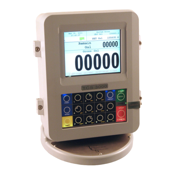
The Open Software Architecture provides the option of a simple “Pump & Print” delivery or a custom measure- ment solution. The TCS 3000 features a 4.5”x 3.5” full color VGA display screen, multiple delivery screens and a backlit alpha-numeric keypad for the user interface. Available in flexible mounting configurations of 75 or 90 degree displays for meter mounting, and a remote mounting. -
Page 5: Dimensions
TCS 3000 Installation The USB0 and USB1 ports are for maintenance only. To access these connectors, power to the unit must be disconnected and the area known to be free of ignitable gas or equivalent. COMMUNICATION Four (4) RS 485 output, 2-wire half duplex, custom protocol; 9600 baud, 8 bit, no parity, 1 stop bit One (1) RS 232 output, 9600 baud;... -
Page 6: 682 Piston Meter Installation
3. Slide the Drive Coupling onto the Meter Drive Shaft. 4. Rotate the TCS 3000 register until the display is facing in the desired direction and check to see that the meter holes align with the holes at the base of the TCS 3000 register. -
Page 7: 700 Rotary Meter Installation
4. Slide the Drive Coupling onto the Meter Drive Shaft. 5. Rotate the TCS 3000 register until the display is facing in the desired direction and check to see that the meter holes align with the holes at the base of the TCS 3000 register. -
Page 8: Remote Meter Installation
Installation Procedure — 3000 Remote Mount Before beginning the installation of the TCS 3000 register, unpack the entire contents of the packaging in a safe loca- tion where you will not misplace any of the parts. Lay out the parts as they would be installed. This will ensure that you have all the correct parts for the installation. -
Page 9: Remote Meter Mounting Dimensions
TCS 3000 Installation Installation Procedure — 3000 Remote Mount Dimensions—Inches (Millimeters) Total Control Systems www.tcsmeters.com... -
Page 10: Grounding Strap Installation
TCS 3000 Installation Installation Procedure — Grounding Strap #8 Grounding Strap Zip Ties 1/4” Hardware TCS 300597, Grounding Strap Kit Installation Procedure: GROUNDING A TRUCK SEAT: Mount ground strap using sup- plied hardware or an existing Identify any adjustable, shock absorbing seat in the truck cab. -
Page 11: Power On Time Relay Installation
Power On Timing Relay When installing the TCS 3000 register on delivery tank trucks, it is recommended to use a timing relay for safe startup of the TCS 3000 registration. Install the TCS 300289 Power On Time Relay from the Accessory Ignition (ACC) to the TCS 3000 register for a selectable time (Seconds) open of power. -
Page 12: Direct Mount Pulser Installation
TCS 3000 Installation Installation Procedure — Direct Mount Pulser GND — GND +5V — VIN TAHA1 — CHA Direct Mount Pulser TAHB1 — CHB 5VDC SHUNT www.tcsmeters.com Total Control Systems... -
Page 13: Test Pulser Installation
Installation Procedure — Test Pulser Prior to putting the liquid handling system into service, the distributor can utilize the TCS 3000 register TEST PULSER to verify that all Inputs/Outputs are working correctly. The Test Pulser will simulate an actual product delivery without having to pump product through the meter. -
Page 14: Pump Control Installation
1. Locate the Pump Control (PMP. CRL) position on the terminal board. 2. Screw the cable gland into the back of the TCS 3000 register and tighten into the housing. 3. Run the Pump Control to the onboard computer or programma- ble logic controller (PLC) wiring through the cable gland. -
Page 15: Additive Injection Pump Installation
TCS 3000 Installation Installation Procedure — Additive Injection Pump There are two selections for managing Additive Injection Pumps; External and Piston. EXTERNAL: The External function for Additive Injection is to provide an positive output signal during the entire delivery pro- BLACK cess to manage an external additive injection pump. -
Page 16: Electronic Air Eliminator - Float
Installation Procedure: 1. Locate the air eliminator float wiring on the metering system. 2. Install the cable gland into the back of the TCS 3000 register and tighten into the housing. 3. Run the air eliminator float wiring through the cable gland. -
Page 17: Electronic Air Eliminator - Vibronic
Installation Procedure: 1. Connect Independent +24VDC to Terminal Block L1 in the Vibronic Sensor 2. Connect Terminal Block 7 to “GND” and Terminal Block 8 to “Air Elim.” under Air Eliminator Section of the TCS 3000 register. 3. Set the Dip Switch on the Vibronic Sensor to the MIN Position. -
Page 18: Lpg 1-Stage Security Valve Installation
4. Once the solenoid is wired, run the corresponding wire as pictured using a minimum of 18 gauge shielded cable into the back of the TCS 3000 register. The 3 Way valve will be wired into Solenoid 2 on the terminal board. -
Page 19: Lpg 2-Stage Preset Valve Installation
4. Once the solenoid is wired, run the corresponding wire as pictured using a minimum of 18 gauge shielded cable into the back of the TCS 3000 register. The 3-Way Valve will be wired into Solenoid 1 (S1) on the terminal board and the Slow Flow Bypass Valve will be wired into Solenoid 2 (S2). -
Page 20: 1-Stage Security Valve Installation
3. Once the solenoid is wired, run the corresponding wire as pic- tured using a minimum of 18 gauge shielded cable into the back of the TCS 3000 register. 4. Insert the solenoid wiring into the cable gland. Wire the solenoid into the correct solenoid location on the terminal board. -
Page 21: 2-Stage Preset Valve Installation
3. Once the solenoids are wired, run the corresponding wire as pic- tured using a minimum of 18 gauge shielded cable into the back of the TCS 3000 register. 4. Insert the solenoid wiring into the cable gland. Wire the solenoid into the correct solenoid location on the terminal board. -
Page 22: Temperature Probe Installation
7. Compress the cable gland on the TCS3000 register until it is snug on the temperature probe wire. 8. Run the temperature probe wiring to the back of the TCS 3000 register. Insert the wiring into the third cable gland from the top of the register as in the illustration above. -
Page 23: Temperature Probe Installation Kits
TCS 3000 Installation Installation Procedure — Temperature Probe Kit TCS 3000 RTD Probe/Aluminum Thermowell Kit Item TCS 300811 Cable Gland, 1/2 NPT UL TCS 300133 O-Ring, 1/2 NPT Gland TCS 300255 4 Wire 100 Ω Temperature Probe TCS 300701 Temperature Probe Jacket... -
Page 24: Daisy Chain Communication
TCS 3000 Installation Installation Procedure — Daisy Chain Communication Daisy Chain: Daisy Chain is used for linking multiple registers together to use one printer or modem to link multiple registers to the database. To Daisy Chain the Registers use a two wire 22 gauge shielded cable. Nominate one Register to be the Host. -
Page 25: Printer Installation
TCS 3000 Installation Installation Procedure — Printer Installation Procedure: 1. Find a suitable location for the printer appropriate to your application. 2. Secure the printer in place with the Velcro strip provided. 3. Wire the power and communication cables into the back of the printer. -
Page 26: Printer Installation Kits
Velcro 4” X 5” TCS 300721 TCS 300721 Epson Printer TEL TMU295-011 TEL TMU295-011 Wehof Order Form TCS WEHOF TCS WEHOF TCS 3000 Epson Slip 24 VDC Print Kit Item TCS 300885 TCS 300985 Metric Cable Gland TCS 300244 TCS 300254 O-Ring, Gland... -
Page 27: Printer Installation Kits (Continued)
Velcro 4” X 5” TCS 300721 TCS 300721 Roll Printer TEL TMU220A103 TEL TMU220A103 Wehof Order Form TCS WEHOF TCS WEHOF TCS 3000 Epson Roll 24 VDC Print Kit Item TCS 300884 TCS 300984 Metric Cable Gland TCS 300244 TCS 300254 O-Ring, Gland... -
Page 28: Printer Installation Kits (Continued)
Ciztizen Bluetooth Print TCS 300723 TCS 300723 DC Truck Adapter/Citize TCS 300724 TCS 300724 Wehof Order Form TCS WEHOF TCS WEHOF *Bluetooth Modem will not pair with other devices, unless TCS Programs the device at the Factory* www.tcsmeters.com Total Control Systems... -
Page 29: Power Off Time Relay Installation
Power Off Timing Relay When installing the TCS 3000 registration on delivery tank trucks with Cellular Modems, it is recommended to provide a timing re- lay for the power off of the modem and register to completely transmit all delivery records. Install the Power Off Time Relay from the Accessory Switch (ACC) to the TCS 3000 register for a selectable time (Seconds) open of power. -
Page 30: Radio Modem Installation
1. Wire the 9DB Pin Communication Cable to the Computer (COMP.) port BLACK of the TCS 3000 register terminal board. 2. Radio modems can be powered within the TCS 3000 register, via the Power Input. 3. Antenna must be connected to cellular modem for there to be any activity. -
Page 31: Sierra Cellular Modem Installation
1. Wire the 9DB Pin Communication Cable to the Computer (COMP.) port of BLUE BLACK the TCS 3000 register terminal board. 2. Cellular modems come with their own Power Cable & Plug. The Red & White wire must be wired to the External Power Source (accessory switch) together. -
Page 32: Maestro Cellular Modem Installation
1. Wire the 15DB Pin Communication Cable to the Computer (COMP.) port of BLUE BLACK the TCS 3000 register terminal board. 2. Cellular modems come with a Power Cable & Plug. The Green wire must be wired to the External Power Source (accessory switch) together. The White wire must be wired to Battery ground. -
Page 33: Remote Display Installation
External Power Source Installation Procedure: See Red Lion, Omega or Tekinno serial slave display manuals for RS-485 programming and wiring Instructions. WARNING: The external remote display requires an External Power Source, do not pull power from the TCS 3000 regis- ter. www.tcsmeters.com... -
Page 34: 1-Channel Communication Board Installation
TCS 3000 Installation Installation Procedure — 1 Channel Communication Installation COMMUNICATION BOARD M4 X 11 STANDOFF M4 X 14 STANDOFF SCREWS WIRING SHIELD Installation Procedure: 1. Remove the six Screws holding the Wiring Shield to the M8 x 27 Standoffs. -
Page 35: 1-Channel Differential Pressure (Dp) Installation
TCS 3000 Installation Installation Procedure — Differential Pressure GTP 7534 Differential Pressure Piston Gauge with Rotary Encoder www.tcsmeters.com Total Control Systems... -
Page 36: 1-Channel Tank Level Monitor Installation
TCS 3000 Installation Installation Procedure — 1 Tank Level Monitor TO: 4-20mA Input from Tank Monitor www.tcsmeters.com Total Control Systems... -
Page 37: 8-Channel Tank Level & Dp Installation
TCS 3000 Installation Installation Procedure — 8 Channel Communication www.tcsmeters.com Total Control Systems... -
Page 38: Typical Wiring Diagram
TCS 3000 Installation Installation Procedure—Wiring Diagrams WHITE WHITE www.tcsmeters.com Total Control Systems... -
Page 39: Software Version Upgrade Instructions
NOTE: The new software upgrade should be the ONLY file on the drive. 2. Open the TCS 3000 register. On the front cover of the register, there are 2 mini-USB connections. Using a factory supplied USB cable, attach the thumb drive to the USB port closest to the inside of the register. This port is the highest on the circuit board of the two. -
Page 40: Replacement Front Cover Computer Instructions
TCS 3000 Installation Installation Procedure — Replacement Register Front Cover HINGE PIN ALLEN SCREW FRONT COVER REPLACEMENT SET SCREW SOCKET SCREW 50 PIN RIBBON REQUIRED TOOLS: POWER RIBBON • 2 mm Allen Wrench • 3 mm Allen Wrench • 5 mm Allen Wrench •... -
Page 41: Parts Schematic
TCS 3000 Installation Total Control Systems www.tcsmeters.com... -
Page 42: Warranty
TCS has not au- thorized on its behalf any representation or warranties to be made, nor any liability to be assumed except as expressly provided herein;... - Page 43 NOTES...
- Page 44 TCS900041 REV. 8 2515 Charleston Place Fort Wayne, IN 46808 Toll Free: (800) 348-4753 Phone: (260) 484-0382 Fax: (260) 484-9230 Email: sales@tcsmeters.com Website: www.tcsmeters.com Total Control Systems Total Control Systems www.tcsmeters.com...
Need help?
Do you have a question about the TCS 3000 and is the answer not in the manual?
Questions and answers