TCS 3000 Installation Manual
Electronic meter register and flow computer
Hide thumbs
Also See for 3000:
- Installation manual (44 pages) ,
- Operation manual (40 pages) ,
- Setup & operation manual (52 pages)
Table of Contents
Advertisement
Advertisement
Table of Contents

Related Manuals for TCS 3000


Summary of Contents for TCS 3000
- Page 1 TCS 3000 Catalog Title REGISTER Catalog Subtitle Installation Manual...
-
Page 2: Table Of Contents
Table of Contents Table of Contents Daisy Chain (Printer) Receipt & Inspection Daisy Chain (Modem) Notice Standard Wiring Introduction Quick Disconnect Wiring System Specifications Software Update 700 Meter Warranty Information 682 Meter Notes Remote Mount Electronic Air Eliminator 3-Way LPG Valve 655-21 Single Stage Valve 755-21 Single Stage Valve 755-31 Single Stage Valve... -
Page 3: Receipt & Inspection
TCS makes no warranties, express or implied, including the implied warranties of merchantability and fitness for a particular purpose with respect to this manual and, in no event, shall TCS be liable for special or consequential damages including, but not limited to, loss of production, loss of profits, etc. -
Page 4: Introduction
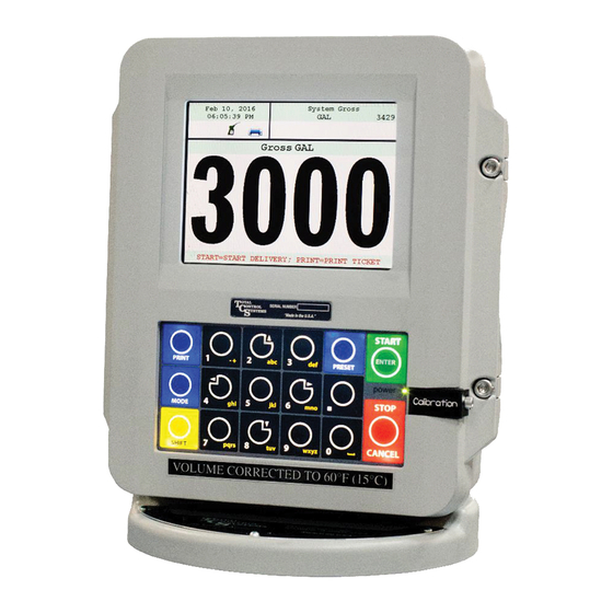
The Open Software Architecture provides the option of a simple “Pump & Print” delivery or a custom measure- ment solution. The TCS 3000 features a 4.5”x 3.5” full color VGA display screen, multiple delivery screens and a flexible mounting with backlit alpha-numeric keypad for the user interface. Available in flexible mounting configurations of 75 or 90 degree displays for meter mounting, and a remote mounting. - Page 5 TCS 3000 Installation COMMUNICATION Four RS 485 output, 2-wire half duplex, custom protocol; 9600 baud, 8 bit, no parity, 1 stop bit One RS 232 output, 9600 baud; 8 bit, no parity, 1 stop bit WARNINGS: SUITABLE FOR USE IN CLASS 1, DIVISION 2, GROUPS C AND D HAZARDOUS LOCATIONS, OR UN- CLASSIFIED LOCATIONS.
-
Page 6: 700 Meter
4. Slide the Adaptor onto the Meter Drive Shaft. 5. Rotate the TCS 3000 until the display is facing in the desired direction and check to see that the meter holes align with the holes at the base of the TCS 3000. - Page 7 TCS 3000 Installation...
- Page 8 3. Slide the Adaptor onto the Meter Drive Shaft. 4. Rotate the TCS 3000 until the display is facing in the desired direction and check to see that the meter holes align with the holes at the base of the TCS 3000.
- Page 9 TCS 3000 Installation...
-
Page 10: Remote Mount
Installation Procedure—3000 Remote Mount/Pulser Before beginning the installation of the TCS 3000, unpack the entire contents of the packaging in a safe location where you will not misplace any of the parts. Lay out the parts as they would be installed on the truck. This will ensure that you have all the correct parts for the installation. - Page 11 TCS 3000 Installation...
-
Page 12: Electronic Air Eliminator
1. Locate the air eliminator float wiring in the metering system. 2. Screw the cable gland into the back of the TCS 3000 and tighten into the housing. 3. Run the air eliminator float wiring in the cable gland. Wire the air eliminator float into the correct location on the terminal board. - Page 13 Locate the air eliminator solenoid wiring in the metering system. Screw the cable gland into the back of the TCS 3000 and tighten into the housing. 7. Run the air eliminator solenoid wiring in the cable gland. Wire the air eliminator solenoid into the correct location on the terminal board.
-
Page 14: 3-Way Lpg Valve
1. Using the bolts and gasket provided, install the valve on the outlet side of the meter. 2. Follow the instructions provided with the valve (TCS ) for wiring the solenoid. Mount the 3 Way Valve directly to the TCS3000 and follow the instructions provided with the Valve. - Page 15 TCS 3000 Installation Versa Valve S1 (Main) S2 (Bypass)
-
Page 16: 655-21 Single Stage Valve
1. Using the bolts and gasket provided, install the valve on the outlet side of the meter. 2. Follow the instructions provided with the valve (TCS 9000051) for wiring the solenoid. 3. Once the solenoid is wired, run the corresponding wire as pictured using a minimum of 22gauge shielded cable into the back of the TCS 3000. -
Page 17: 755-21 Single Stage Valve
1. Using the bolts and gasket provided, install the valve on the outlet side of the meter. 2. Follow the instructions provided with the valve (TCS 9000051) for wiring the solenoid. 3. Once the solenoid is wired, run the corresponding wire as pictured using a minimum of 22gauge shielded cable into the back of the TCS 3000. -
Page 18: 755-31 Single Stage Valve
1. Using the bolts and gasket provided, install the valve on the outlet side of the meter. 2. Follow the instructions provided with the valve (TCS 9000051) for wiring the solenoid. 3. Once the solenoid is wired, run the corresponding wire as pictured using a minimum of 22gauge shielded cable into the back of the TCS 3000. -
Page 19: 755-20 2-Stage Valve
1. Using the bolts and gasket provided, install the valve on the outlet side of the meter. 2. Follow the instructions provided with the valve (TCS 9000051) for wiring the solenoid. 3. Once the solenoid is wired, run the corresponding wire as pictured using a minimum of 22gauge shielded cable into the back of the TCS 3000. -
Page 20: 755-30 2-Stage Valve
1. Using the bolts and gasket provided, install the valve on the outlet side of the meter. 2. Follow the instructions provided with the valve (TCS 9000051) for wiring the solenoid. 3. Once the solenoid is wired, run the corresponding wire as pictured using a minimum of 22gauge shielded cable into the back of the TCS 3000. -
Page 21: Vibronic Sensor
TCS 3000 Installation Installation Procedure—Vibronic Sensor Installation Procedure: Instructions to follow. -
Page 22: Timing Relay
Installation Procedure—Timing Relay... -
Page 23: Temperature Probe
TCS 3000 Installation Installation Procedure—Temperature Probe Installation Procedure: 1. Locate the thermowell in the metering system. 2. Slide the temperature probe jacket over the temperature probe wire until it covers the entire wire. 3. Screw the cable gland into the thermowell and tighten. Squeeze the Copper Anti Sieze on the metal tip of the temperature probe. - Page 24 Installation Procedure—Temperature Probe Cont. 8. Run the temperature probe wiring to the back of the TCS 3000. Insert the wiring into the third cable gland from the top of the register as pictured on page 18. 9. Leave slack in the temperature probe wiring and tighten the cable gland down on the temperature probe. If Needed the probe wire may be trimmed of excess wire before tightening down the cable gland.
- Page 25 TCS 300719 Copper Antiseize 2 Gram TCS 300749 Thermowell 1/2” Stainless TCS 740400 Thermowell 3/8” Stainless TCS 740405 TCS 3000 RTD Probe/SS Thermowell Kit (TCS 300815) Item TCS P/N Cable Gland M20X1.5 UL TCS 300244 O-Ring Buna M20 Gland TCS 300245...
-
Page 26: Printer
Installation Procedure—Printer Installation Procedure: 1. Find a suitable location for the printer appropriate to your application. 2. Secure the printer in place with the Velcro strip provided. 3. Wire the power and communication cables into the back of the printer. 4. - Page 27 Epson Printer TEL TMU295-011 TEL TMU295-011 Wehof Order Form TCS WEHOF TCS WEHOF TCS 3000 Epson Slip 24 VDC Print Kit (Metric TCS 300885 / NPT TCS 300985) Item Metric TCS P/N NPT TCS P/N Cable Gland M20X1.5 UL TCS 300244...
- Page 28 Roll Printer TEL TMU220A103 TEL TMU220A103 Wehof Order Form TCS WEHOF TCS WEHOF TCS 3000 Epson Roll 24 VDC Print Kit (Metric TCS 300884 / NPT TCS 300984) Item Metric TCS P/N NPT TCS P/N Cable Gland M20X1.5 UL TCS 300244...
- Page 29 TCS 300722 TCS 300722 Ciztizen Bluetooth Print TCS 300723 TCS 300723 DC Truck Adapter/Citize TCS 300724 TCS 300724 Wehof Order Form TCS WEHOF TCS WEHOF *Bluetooth Modem will not pair with other devices, unless TCS Programs the device at the Factory*...
- Page 30 Citizen Wifi Printer CM TCS 300750 TCS 300750 Wehof Order Form TCS WEHOF TCS WEHOF TCS 3000 Epson Slip 12V QD Print Kit (Metric TCS 300891 / NPT TCS 300991) Item Metric TCS P/N NPT TCS P/N Cable Gland M20X1.5 UL TCS 300244...
- Page 31 TCS 3000 Installation TCS 3000 Epson Slip Print 110V QD Kit (Metric TCS 300892 / NPT TCS 300992) Item Metric TCS P/N NPT TCS P/N Cable Gland M20X1.5 UL TCS 300244 O-Ring, Buna M20 Glad TCS 300245 Cable Gland, 1/2 NPT Gland...
- Page 32 TCS 3000 Epson Roll 110V QD Print Kit (Metric TCS 300896 / NPT 300996) Item Metric TCS P/N NPT TCS P/N Velcro 4” X 5” TCS 300721 TCS 300721 Comm. Cable 35’ Quick DI TCS 300762 TCS 300762 Quick Disc Splitter W/2...
-
Page 33: Remote Display
TCS 3000 Installation Installation Procedure—Remote Display Installation Procedure: Instructions to follow. -
Page 34: Daisy Chain (Printer)
Installation Procedure—Daisy Chain Printer Daisy Chain: Daisy Chain is used for linking multiple registers together to use one printer or to link multiple registers to the data- base. To Daisy Chain the Registers use a two wire 22 gauge shielded cable. Nominate one Register to be the Host. Once you’ve chosen which Register will be the Host the other Registers will be considered the clients. - Page 35 TCS 3000 Installation Daisy Chain for the Printer Connect the Printer to the Host Register. To set the Host : Enable the Printer: SYSTEM MENU → SYSTEM SETTINGS → PRINTER SETTINGS → ENABLE/DISABLE PRINTER → ENABLE PRINTER Select the Printer: PRINTER SETTINGS →...
-
Page 36: Daisy Chain (Modem)
Installation Procedure—Daisy Chain Modem Daisy Chain: Daisy Chain is used for linking multiple registers together to use one printer or to link multiple registers to the data- base. To Daisy Chain the Registers use a two wire 22 gauge shielded cable. Nominate one Register to be the Host. Once you’ve chosen which Register will be the Host the other Registers will be considered the clients. - Page 37 TCS 3000 Installation Selecting the Host Register Select Register as Host: PRINTER SETTINGS → DISABLE/ENABLE HOST → ENABLE Select the Client Range: PRINTER SETTINGS → PRINTER HOST → CLIENTS ADDRESS RANGE → CLIENTS RANGE START ADDRESS [ Enter 2 and Select] →...
-
Page 38: Standard Wiring
Installation Procedure—Wiring Diagrams Standard Wiring... -
Page 39: Quick Disconnect Wiring
TCS 3000 Installation Quick Disconnect Wiring... -
Page 40: Software Update
NOTE: The new software upgrade should be the ONLY file on the drive. 2. Open the TCS 3000 register. On the front cover of the register, there are 2 mini-USB connections. Using a factory supplied USB cable, attach the thumb drive to the USB port closest to the inside of the register. This port is the highest on the circuit board of the two. -
Page 41: Warranty Information
TCS has not au- thorized on its behalf any representation or warranties to be made, nor any liability to be assumed except as expressly provided herein;... - Page 43 TCS 3000 Installation...
- Page 44 TCS900041 REV. 2 2515 Charleston Place Fort Wayne, IN 46808 Toll Free: (800) 348-4753 Phone: (260) 484-0382 Fax: (260) 484-9230 Email: sales@tcsmeters.com Website: www.tcsmeters.com...
Need help?
Do you have a question about the 3000 and is the answer not in the manual?
Questions and answers