Page 1
TCS900004, Rev.4 07/12/2016 700-40/45 Cat alog Title Rotary Meter Catalog Subtitle Installation, Operation & Maintenance Manual
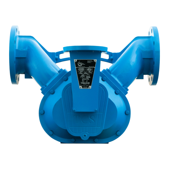
 Check us out at www.TCSmeters.com...
TCS900004, Rev.4 07/12/2016 Page 2 Table of Contents Safety Warning Symbols Air Eliminator Strainer Assembly (Continued) Receipt & Inspection Hydraulic Preset Valve Assembly Notice Hydraulic Preset Valve Assembly (Continued) Torque Specifications Meter Specifications Disassembly of Meter Meter Types Disassembly of Meter (Continued) Material of Construction Disassembly of Meter (Continued) System Recommendations...
TCS makes no warranties, express or implied, including the implied warranties of merchantability and fitness for a particular purpose with respect to this manual and, in no event, shall TCS be liable for special or consequential damages including, but not limited to, loss of production, loss of profits, etc.
Page 4
07/12/2016 Page 4 Meter Overview The TCS Model 700 series flow meter is a simple and efficient design. The meter consists of a single fluid chamber that contains a single blocking rotor and two displacement rotors whose rotation is synchronized with mating gears.
4” NPT Flange Connection, 3” NPT Flange. Optional BSPT, Slip Weld or ANSI flanges available upon request. Flow Rate: 700-40 up to 500 GPM (1893 LPM) 700-45 up to 600 GPM (2271 LPM); only for fluids under 225 Maximum Pressure: 150 PSI (10.5 BAR)
TCS900004, Rev.4 07/12/2016 Page 7 System Recommendations (Continued) Control Valves Safety and isolation valves should be used throughout the metering system. In any pumping system where there is one (1) pump and multiple flow meters, a digital or hydro-mechanical Rate-of-Flow control valve must be used at each flow meter to prevent over-speeding of the flow meters.
Page 8
TCS900004, Rev.4 07/12/2016 Page 8 System Recommendations (Continued) Thermal Shock The metal parts within the flow meter will expand or contract with variations in the system operating temperature. sudden or immediate temperature increases of 68 F (20 C) degrees or more are For any systems where possible, the meter will require clearance rotors.
Page 9
TCS900004, Rev.4 07/12/2016 Page 9 Check us out at www.TCSmeters.com...
Page 10
TCS900004, Rev.4 07/12/2016 Page 10 Check us out at www.TCSmeters.com...
TCS900004, Rev.4 07/12/2016 Page 11 Start up Recommendations ¡WARNING! Test equipment should be grounded to prevent a possible spark. Test area should have no ignition source. Operators should wear personal protection and prevent any product exposure and environmental issues. Start-up instruction for new installations or after maintenance and repairs: 1) Only properly trained personal should design, install, or operate metering system.
TCS900004, Rev.4 07/12/2016 Page 12 Start-Up Recommendations (CONTINUED) 14) When operating the meter with accessories, valves should be opened slowly to avoid a pressure surge that can damage the meter or air eliminator. System pressures should be maintained below 70 PSI (4.9 BAR). 15) Custody transfer metering systems must be calibrated by a regulatory agency before product can be sold off the meter.
TCS900004, Rev.4 07/12/2016 Page 13 Meter Calibration The method of proving should be selected, and necessary provisions made, during the design stage of the installation. Of the most commonly used systems, portable provers have the advantage of more closely reproducing the conditions under which the product is normally delivered.
TCS900004, Rev.4 07/12/2016 Page 14 Meter Calibration (Continued) Making the Tests Reset the register to zero, and run the required test quantity through the meter. Do not exceed the maximum recommended rate of flow for the meter. Maximum and minimum recommended rates of flow for each 700 series flow meter is marked on the meter identification plate and also in the maintenance manual.
TCS900004, Rev.4 07/12/2016 Page 15 Meter Calibration (Continued) Temperature Correction If the testing conditions are such that the temperature of the liquid differs by more than a few degrees between the meter and the prover, it is advisable to apply temperature correction to the prover readings. Thermowells must be installed into the system and temperature readings must be taken during test runs at the meter and in the prover.
Page 16
TCS900004, Rev.4 07/12/2016 Page 16 Split Compartment Test Purpose: A product depletion test verifies the proper operation of the air elimination system when the storage tank for the product being measured is pumped dry. This test is necessary for meters that may drain a tank completely, such as a vehicle tank meter.
Page 17
TCS900004, Rev.4 07/12/2016 Page 17 Split Compartment Test (Continued) Single Compartment Test Procedure: The test of single-compartment tanks is easier to accomplish if there is a quick-connect hose coupling between the compartment valve and the pump that supplies product to the meter. If the system does not have quick-connect couplings between the compartment and the meter, an additional source of sufficient product at the test site is required.
Page 18
TCS900004, Rev.4 07/12/2016 Page 18 Split Compartment Test (Continued) With a quick-connect coupling: During a normal full flow test run, close the compartment valve when the prover is approximately one-half full to its normal capacity. Then slowly and carefully disconnect the quick-connect coupling, allowing the pump to drain the supply line.
Page 19
Only fully trained personnel should be involved in maintenance. Failure to use original TCS replacement parts will void any Weights and Measures approvals, warranty and risk damage to the meter system.
Page 20
TCS900004, Rev.4 07/12/2016 Page 20 Maintenance (CONTINUED) ¡WARNING! Test equipment should be grounded to prevent a possible spark. Test area should have no ignition source. Operators should wear personal protection and prevent any product exposure and environmental issues. 10) When removing gaskets or O-Rings, carefully check for damage or corrosion. Any cracked, rough, worn, elongated or swollen O-Rings must be replaced.
Page 21
TCS900004, Rev.4 07/12/2016 Page 21 700-40 / 700-45 Dimensions All measurements are in inches (millimeters). Check us out at www.TCSmeters.com...
Page 22
TCS900004, Rev.4 07/12/2016 Page 22 700-40 / 700-45 Meter Assembly Check us out at www.TCSmeters.com...
704013 704013 704013 Basket Cover; One 1/2” NPT Port 744155 744156 744155 744156 Strainer Cold Weather Seal Kit—TCS 744078 Contents: All seals are low temperature Nitrile Rubber (4) Top Seal Qty. 1 (8) Seal Ring Qty. 1 (14) Flange O-Ring Qty.
750004 750004 750004 Lever Knob 753052 753052 753052 Valve Cold Weather Seal Kit—TCS 754078 All seals are low temperature Nitrile Rubber, FKM or PTFE Contents: (21) Lower Seal Qty. 1 (20) Upper Seal Qty. 1 (*) Flange O-Ring Qty. 2 (15) Cover Seal Qty.
TCS900004, Rev.4 07/12/2016 Page 28 Torque Specifications 700-40/45 METER ASSEMBLY Foot Lbs. Newton Meter Part Number Tool Bolt/Nut Size & Description Unlubricated Lubricated Unlubricated Lubricated TCS 704016 9/16” hex 3/8-16 UNC 2B 19.7 11.8 26.7 16.0 Cover Screws wrench/socket TCS 700040 7/16”...
Page 29
TCS900004, Rev.4 07/12/2016 Page 29 Drive Components Removing the Dust Cover Cut dust cover seal. Remove the dust cover screws with a standard flathead screwdriver. Note the setting on calibration adjuster. Note the position of the drive gear (either above or below the packing gland pinion). Removing the Adjuster Loosen the retaining screws using a standard flathead screwdriver.
TCS900004, Rev.4 07/12/2016 Page 30 Disassembly of Meter (Continued) ¡WARNING! All internal pressure must be relieved to ZERO (0) pressure before beginning disassembly of meter or components Draining Meter & Removing Counter Support Drain the meter by turning it on either the inlet or outlet side. Remove the counter bracket screws with a hex wrench or socket driver.
TCS900004, Rev.4 07/12/2016 Page 31 Disassembly of Meter (Continued) Front & Rear Cover Remove the screws on the front cover using a socket or box wrench. Remove front cover. Remove the screws on the back and remove rear cover. Remove the O-Ring from both sides of the housing Rotor Gears Using a spare displacement rotor gear, place it between the rotor and blocking gear on the meter.
TCS900004, Rev.4 07/12/2016 Page 32 Disassembly of Meter (Continued) Removing Bearing Plate Remove the bearing plate retaining screws with a standard flathead screwdriver. To remove bearing plate & rotors, insert a screwdriver into the notches near the dowel pins. Gently pry the bearing plate off the dowel pins and slide out the bearing plate and rotors from the housing.
TCS900004, Rev.4 07/12/2016 Page 33 Inspection of Parts Inspect the surfaces of rotors, bearing plates, meter housing and gear teeth for any damage or wear. Replace parts as needed. GEAR WEAR A) Meter has been run on air. B) Meter has been operated at CHAMBER WEAR a higher volume capacity than what is rated...
TCS900004, Rev.4 07/12/2016 Page 34 Reassembly of Meter Reinstalling Rotors Install rear bearing plate on meter. Insert threaded end of blocking rotor and the right displacement rotor into front gear plate (reinsert rotor keys if necessary). Align the two rotors (see picture 3) before applying gears. Rotor Gear Timing Slide on blocking rotor gear and position the ‘arrow’...
TCS900004, Rev.4 07/12/2016 Page 35 Reassembly of Meter Reinstalling Bearing Plate Align rotors on bearing plate (see picture) before inserting into meter. Slide front bearing plate with rotors into meter housing and rear bearing plate. Again, rotate gears to make sure they turn freely within the housing before proceeding. Reinstalling Rotor Gears &...
TCS900004, Rev.4 07/12/2016 Page 36 Reassembly of Meter Reinstalling Packing Capsule & Front/Rear Covers Reinstall cover O-Rings on the front and rear of meter housing. Reinsert packing capsule into front cover of meter with retaining plate and tighten screws. When attaching front cover, align packing capsule blade with the slot on the blocking rotor sleeve. Tighten all front cover screws.
TCS900004, Rev.4 07/12/2016 Page 37 Reassembly of Meter (Continued) Reinstalling Adjuster Reinsert the adjuster into the top of the counter support and assuring that it mates with the drive shaft. Tighten the screws that secure the adjuster plate to the counter support. Reinstalling Dust Cover Reattach dust cover and tighten the screws.
TCS900004, Rev.4 07/12/2016 Page 38 Page 38 Disassembly of 720 Strainer Assembly ¡WARNING! All internal pressure must be relieved to ZERO (0) pressure before beginning disassembly of meter or components Using a hex or socket wrench, remove the four screws and washers from the cover plate. Remove the cover plate and O-Ring from the housing.
TCS900004, Rev.4 07/12/2016 Page 39 Page 39 Disassembly of 730 Air Eliminator Assembly ¡WARNING! All internal pressure must be relieved to ZERO (0) pressure before beginning disassembly of meter or components Using a 1/2” wrench or socket, remove the cover screws from air eliminator cover plate. Remove cover plate.
Page 40
TCS900004, Rev.4 07/12/2016 Page 40 Disassembly of 750-40 Hydraulic Valve ¡WARNING! All internal pressure must be relieved to ZERO (0) pressure before beginning disassembly of meter or components Drain all fluid from metering system prior to valve removal. Using a hex or socket wrench, remove the four screws connecting the valve to the meter. Remove valve from meter and piping.
Page 41
TCS900004, Rev.4 07/12/2016 Page 41 Disassembly of 750-40 Hydraulic Valve Remove the piston guide from the valve body. Remove and inspect the upper and lower seals and replace as needed. Using a flathead screwdriver, gently remove the valve body O-Ring, inspect and replace if needed. Reassembly of 750-40 Hydraulic Valve Place the seal into valve housing.
Page 42
4) Inspect and clean seal chamber. 5) Apply thin layer of grease to the shaft and seal chamber. 6) Install new seal (TCS 754065) over shaft, followed by the sleeve (TCS 754050), bearing sleeve (TCS 754055) and the bearing (TCS 754060).
Page 43
TCS900004, Rev.4 07/12/2016 Page 43 Meter Trouble Shooting PROBLEM: Leaking packing gland and/or housing A) Check to see whether any O-Rings have been damaged or cover bolts have not been tightened enough. B) Two common causes of packing gland leakage are thermal expansion and hydraulic shock. C) If two valves in a piping system (on either side of the meter) are closed, isolating the meter, and if the temperature rises as little as 1ºF in the system, the possible rise in pressure due to temperature would exceed the working pressure rating of the meter.
Page 44
TCS900004, Rev.4 07/12/2016 Page 44 Page 44 Air Eliminator Trouble Shooting PROBLEM: Product is flowing from the Air Eliminators vents A) Foreign matter located in between seal plate O-Rings and metal reeds. B) The seal plate oring may be worn through service life. C) The seal plate oring may be cut or dislodged and requires replacement.
Page 45
TCS900004, Rev.4 07/12/2016 Page 45 Preset Valve Trouble Shooting PROBLEM: The valve will not close completely. A) The shaft of the piston may be bent from excessive force. B) Debris may be located between the piston and piston guide. C) The upper or lower seals may be worn, swollen from incompatibility or cut from debris. D) The mechanical linkage to the Veeder-Root 7889 preset counter may be tight.
Page 46
TCS900004, Rev.4 07/12/2016 Page 46 Material Safety Data Sheet (MSDS) 24 HOUR EMERGENCY ASSISTANCE GENERAL MSDS ASSISTANCE (260) 833-3173 (260) 484-0301 CODE: RPS ========================================================================================== HAZARD RATING> LEAST-0 SLIGHT-1 MODERATE-2 HIGH-3 EXTREME-4 ========================================================================================== DR LUBRICANTS, INC. DATE: 01/21/06 4611 NEWAYGO ROAD, SUITE D FORT WAYNE, IN 46808 TELEPHONE NUMBER: (260 484-0301 ==========================================================================================...
Page 47
TCS900004, Rev.4 07/12/2016 Page 47 Page 47 Material Safety Data Sheet (Continued) PRODUCT: RP 1060 PAGE - 2 ========================================================================================== SECTION IV - FIRE AND EXPLOSION HAZARD DATA ========================================================================================== UNUSUAL FIRE AND EXPLOSION HAZARDS : DO NOT DIRECT A SOLID STREAM OF WATER ONTO BURNING PRODUCT.
Page 48
TCS900004, Rev.4 07/12/2016 Page 48 Material Safety Data Sheet (Continued) PRODUCT: RP 1060 PAGE - 3 ========================================================================================== SECTION VII - SPILL OR LEAK PROCEDURES ========================================================================================== STEPS TO BE TAKEN IN CASE MATERIAL IS RELEASED OR SPILLED: FOR SMALL SPILLS: SOAK UP SPILL WITH ABSORBENT MATERIAL.
Page 49
TCS900004, Rev.4 07/12/2016 Page 49 Material Safety Data Sheet (Continued) PRODUCT: RP 1060 PAGE - 4 ========================================================================================== SECTION X - HMIS/NFPA RATINGS ========================================================================================== HMIS:HEALTH:1 FLAMMABILITY:2 REACTIVITY:0 PERSONAL PROTECTION:C NFPA:HEALTH:1 FLAMMABILITY:2 REACTIVITY:0 SPECIFIC HAZARD: ========================================================================================== SECTION XI - OTHER REGULATORY INFORMATION ========================================================================================== LAND (TDG) PROPER SHIPPING NAME: PETROLEUM DISTILLATES, N.O.S.
Page 50
TCS900004, Rev.4 07/12/2016 Page 50 Notes Check us out at www.TCSmeters.com...
TCS is not responsible for any in or out bound freight. TCS's sole obligation shall represent the buyer's sole and exclusive remedy shall be to repair or at TCS's option to replace any product or part determined to be defective. In no event shall TCS be liable for any special, direct, indirect, incident, consequential or other damages of similar nature, including without limitation, loss of profits, products, production time, or loss of expenses of any nature incurred by the buyer or any third party.
Page 52
TCS900004, Rev.4 07/12/2016 2515 Charleston Place Fort Wayne, IN 46808 Toll Free: (800) 348-4753 Phone: (260) 484-0382 Fax: (260) 484-9230 Email: sales@tcsmeters.com Check us out at www.TCSmeters.com...
Need help?
Do you have a question about the 700-40 and is the answer not in the manual?
Questions and answers