Table of Contents
Advertisement
Quick Links
Instruction manual
General instructions digital
Mass Flow instrument
CORI-FLOW
Doc. no.: 9.17.031I Date: 27-01-2015
ATTENTION
Please read this instruction manual carefully before installing and operating the instrument.
Not following the guidelines could result in personal injury and/or damage to the equipment.
Advertisement
Table of Contents

Related Manuals for BRONKHORST CORI-FLOW


Summary of Contents for BRONKHORST CORI-FLOW
- Page 1 Instruction manual General instructions digital Mass Flow instrument CORI-FLOW Doc. no.: 9.17.031I Date: 27-01-2015 ATTENTION Please read this instruction manual carefully before installing and operating the instrument. Not following the guidelines could result in personal injury and/or damage to the equipment.
- Page 2 BRONKHORST CORI-TECH B.V. SCOPE OF THIS MANUAL This manual covers the general part of digital CORI-FLOW mass flow instruments for gases and liquids. It treats the general instructions needed for the instruments. More information can be found in other documents.
- Page 3 Bronkhorst Cori-Tech B.V. July 2011 Warranty The products of Bronkhorst Cori-Tech B.V. are warranteed against defects in material and workmanship for a period of three years from the date of shipment, provided they are used in accordance with the ordering specifications and the instructions in this manual and that they are not subjected to abuse, physical damage or contamination.
- Page 4 Install the CORI-FLOW Meter/Controller in the line and tighten the fittings according to the instructions of the supplier of the fittings. Choose the mounting position according to the directions given in this manual.
-
Page 5: Table Of Contents
Gas / Liquid flow .......................... 7 1.1.2 Housing ............................7 1.1.3 Valves ............................8 Sensor principles ..........................9 1.2.1 CORI-FLOW sensor ........................9 Valve principles ........................... 9 1.3.1 Solenoid valve ..........................9 1.3.2 Vary-P valve ..........................10 1.3.3 Pilot operated valve ........................10 1.3.4... - Page 6 BRONKHORST CORI-TECH B.V. Appendices Enclosures (if applicable) Hook-up diagram Calibration certificate page 6 9.17.031...
-
Page 7: Introduction
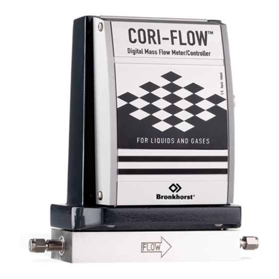
1.1 General description 1.1.1 Gas / Liquid flow The Bronkhorst Cori-Tech B.V. series CORI-FLOW mass-flow meter/controller for gases and liquids is a accurate device for measuring gas and liquid flows up to 100 bar depending on body rating, virtually independent of pressure and temperature changes. The CORI-FLOW is a real mass-flow meter/controller it measures the flow in mass, it does not matter what the properties of the gases or liquids are. -
Page 8: Valves
BRONKHORST CORI-TECH B.V. Controller housing with C5 valve 1.1.3 Valves CORI-FLOW controllers are fitted with a modular valve. The valve is attached by means of a port connector. Valves for liquids C2I valve F-004AI valve C5I valve Direct operating valve for liquids... -
Page 9: Sensor Principles
The extremely small tube displacements are detected by optimally positioned sensors and evaluated electronically. Since the measured phase shift of the sensor signals is proportional to the mass flow, the CORI-FLOW measures the mass flow directly. The measurement principle is independent of the density, temperature, viscosity, pressure or conductivity. -
Page 10: Vary-P Valve
1.4 Software for physical properties of gases and liquids. Bronkhorst Cori-Tech B.V. gathered the physical properties of over 600 fluids in a database called FLUIDAT. Application software, such as FLOW CALCULATIONS, enables the user to calculate properties, not only at 20°C / 1 atm but also at any temperature/pressure combination, both for gases and for liquids. -
Page 11: Installation
If the instruments have been used with toxic or dangerous fluids the customer should pre-clean the instrument. Important: Clearly note, on top of the package, the customer clearance number of Bronkhorst Cori-Tech B.V., namely: NL801989978B01 If applicable, otherwise contact your distributor for local arrangements. -
Page 12: Mounting
Avoid in any case heavy accelerations or mechanical shocks on the instrument. For liquids, mount the CORI-FLOW at a level in the pipe line system where gas enclosure is not possible and be certain that the CORI-FLOW is filled all the time while operating. - Page 13 In order to remove gas bubbles during start-up, flushing with relatively high flow rate for some minutes is recommended. Mount the CORI-FLOW always with screws in the body on a rigid support, the tubing has to be considered flexible, because the tube diameter is relatively low. Please avoid torsion on the piping connected to de CORI-FLOW.
-
Page 14: Notes For Temperature Changes
BRONKHORST CORI-TECH B.V. 2.5 Notes for temperature changes The CORI-FLOW has to be installed in such a way that levels of different temperature within the CORI- FLOW are avoided. Avoid multiple heating and cooling of the instrument. When cleaning, temperature shocks have to be avoided in any case. (max. 1°C/sec) The temperature difference between sensor and fluid should not exceed 50°C. -
Page 15: System Purging
2.12 Seals Bronkhorst Cori-Tech B.V. has gathered a material compatibility chart from a number of sources believed to be reliable. However, it is a general guide only. Operating conditions may substantially change the accuracy of this guide. - Page 16 BRONKHORST CORI-TECH B.V. Connector CORI-FLOW Note: When connecting the system to other devices (e.g. to PLC), be sure that the integrity of the shielding is not affected. Do not use unshielded wire terminals. 1. For FLOW-BUS S(F)TP data (patch) cable connection to M12 connectors follow the instructions of the supplier.
-
Page 17: Electro Static Discharge
Note: Connect the instrument (body) to ground properly (earth potential). OPERATION 3.1 General The Bronkhorst Cori-Tech B.V. instruments are designed in such a way that they will meet user process requirements in the best possible way. The CORI-FLOW meters/controllers can be powered from +15 Vdc to +24 Vdc. -
Page 18: Zeroing
3.3.1 Zeroing with the Micro-switch Before using the instrument zeroing is required. ATTENTION • Set process conditions Zero instrument After warm-up, pressure up the system and fill the CORI-FLOW according to before use the process conditions • Stop flow PROCEDURE... -
Page 19: Start-Up
3.6 Instrument performance 3.6.1 Meters Each meter has a step-response of about 50ms. The special adaptive filtering technique in the CORI-FLOW detects that the flow is changing rapidly and will decrease filtering immediately so a fast response is possible. After the flow change the filter will increase to get a steady signal. - Page 20 BRONKHORST CORI-TECH B.V. Current output signals Sinking Sourcing output output power instrument instrument supply 0V common 0V common For meters only the output signal is available. At analog operation the following parameters are available: - measured value - setpoint (controllers only)
-
Page 21: Bus / Digital Operation
BRONKHORST CORI-TECH B.V. 3.9 BUS / digital operation Operation via fieldbus reduces the amount of cables to build a system of several instruments and offers more parameter values to be monitored/changed by the user. See instruction manual: operating digital mass flow / pressure instruments for more details (document nr. -
Page 22: Maintenance
No routine maintenance is required to be performed on the meters or controllers. In case of severe contamination it may be required to clean the valve orifice separately. 4.2 CORI-FLOW sensor The CORI-FLOW sensor is constructed in such a way that there is little dead volume. The sensor is maintenance free. 4.3 Controllers All sensor types can be combined with a control valve to be operated together as a control loop. -
Page 23: Pilot Operated Valve
BRONKHORST CORI-TECH B.V. 4.4.3 Pilot operated valve This control valve is an indirect control valve, consisting of a spring loaded membrane/orifice system which is positioned by a solenoid operated direct control (pilot valve). The two devices are integrated in one block. -
Page 24: For Liquids
BRONKHORST CORI-TECH B.V. 4.5.2 For Liquids Determine desired ∆p across valve. ∆p must be at least 50% of supply pressure ρ Φ Kv-value calculation ρ ∆ ⋅ 1000 Φ Units: flow ρ (kg / m ) at 20 C density ... -
Page 25: Digital Instrument
BRONKHORST CORI-TECH B.V. DIGITAL INSTRUMENT See document number 9.17.023 for detailed description. This document is available as PDF on the Multibus documentation/software tool CD. INTERFACE DESCRIPTION For a description of the available interfaces see document numbers: 9.17.024 for FLOW-BUS 9.17.025 for PROFIBUS-DP 9.17.026 for DeviceNet... -
Page 26: Troubleshooting
7.1 General For a correct analysis of the proper operation of a CORI-FLOW meter or controller it is recommended to remove the unit from the process line and check it without applying fluid supply pressure. In case the unit is dirty, this can be ascertained immediately by loosening the compression type couplings and, if applicable the flange on the inlet side. -
Page 27: Special Applications
BRONKHORST CORI-TECH B.V. SPECIAL APPLICATIONS The CORI-FLOW can be used with special external valves like a Badger Meter valve and pumps with an analog input (4-20mA or 0-10V) and still be an integrated controller. The CORI-FLOW can also be used as a batch controller for filling purposes.
Need help?
Do you have a question about the CORI-FLOW and is the answer not in the manual?
Questions and answers