
Related Manuals for Palmgren 80341A


Summary of Contents for Palmgren 80341A
- Page 1 & parts list 80341A & 80342A 33″ RADIAL ARM BENCH AND FLOOR DRILL PRESSES Read carefully and follow all safety rules and operating instructions before first use of this product. 30982.29-0111...
-
Page 2: Specifications
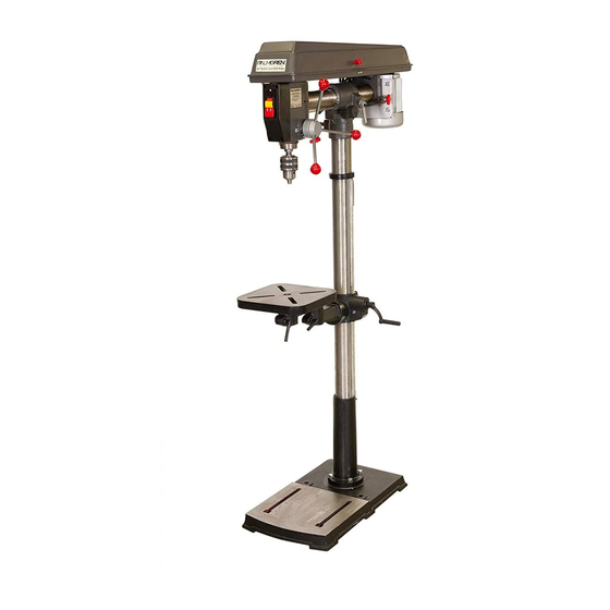
MODEL 80342A FLOOR DRILL PRESS DESCRIPTION A Head Assembly B Column Palmgren Radial Arm Drill Presses feature a heavy cast iron base, C Column Flange work table and head. Head moves 12” forward and backward using D Base a rack and pinion. Head also swivels 360° around column, tilts 90°... -
Page 3: Safety Rules
Palmgren Operating Manual & Parts List 80341A & 80342A • Work area should be properly lighted. UNPACKING (CONTINUED) • Proper electrical outlet should be available for tool. MODEL 80342A Three-prong plug should be plugged directly into properly Chuck size ......... . . 1-16mm, 3JT grounded, three-prong receptacle. - Page 4 Large non-machined portion of rack should be at top. Rack Figure 3 – Mount Column Assembly to Base (80341A) MOUNT COLUMN ASSEMBLY TO BASE (80342A) Refer to Figure 4.
- Page 5 Palmgren Operating Manual & Parts List 80341A & 80342A ASSEMBLY (CONTINUED) • Slide table bracket assembly with rack over column. Place bot- Retaining Ring tom end of rack inside beveled edge of column flange. See Figure 5, page 4. • Slide retaining ring over column with beveled edge down.
- Page 6 Palmgren Operating Manual & Parts List 80341A & 80342A ASSEMBLY (CONTINUED) MOUNT CHUCK AND ARBOR Refer to Figure 22, page 12. MOUNT HEAD ASSEMBLY • Be sure spindle, arbor and chuck tapers are clean and dry. Make Refer to Figures 9 and 10.
-
Page 7: Installation
Palmgren Operating Manual & Parts List 80341A & 80342A Do not remove or alter grounding prong in any manner. In the INSTALLATION event of a malfunction or breakdown, grounding provides a path of least resistance for electrical shock. MOUNT DRILL PRESS... -
Page 8: Operation
Palmgren Operating Manual & Parts List 80341A & 80342A INSTALLATION (CONTINUED) ELECTRICAL CONNECTIONS WARNING: All electrical connections must be performed by a qualified electrician. Make sure unit is off and disconnected from power source while motor is mounted, connected, reconnected or anytime wiring is inspected. -
Page 9: Depth Stop Adjustment
Palmgren Operating Manual & Parts List 80341A & 80342A • Clamp table securely after adjustments have been made. OPERATION (CONTINUED) (See Figure 20). • To return head to 0° vertical position, loosen head angle lock handle, rotate guide pin 90° and tilt head. The guide pin will snap into slot at 0°... -
Page 10: Maintenance
Palmgren Operating Manual & Parts List 80341A & 80342A MAINTENANCE WARNING: Turn switch off and remove plug from power source outlet before maintaining or lubricating your drill press V-BELT Replace V-belt when worn. LUBRICATION The ball bearings are lubricated at the factory and need no further lubrication. -
Page 11: Troubleshooting
Palmgren Operating Manual & Parts List 80341A & 80342A TROUBLESHOOTING SYMPTOM POSSIBLE CAUSES CORRECTIVE ACTION Spindle does not turn 1. No power to drill press 1. Check wiring, fuse or circuit breaker 2. Defective switch 2. Replace switch 3. Defective motor 3. - Page 12 Palmgren Operating Manual & Parts List 80341A & 80342A Figure 22 - Replacement Parts Illustration for Head...
- Page 13 Palmgren Operating Manual & Parts List 80341A & 80342A REPLACEMENT PARTS LIST FOR HEAD Ref. Ref. Description Part No. Qty. Description Part No. Qty. Chuck Key 30535.00 8-1.25mm Hex Nut Chuck with Key (incl. Ref No. 1) 30536.00 Knob 30557.00 Lower Spindle Assembly 30537.00...
- Page 14 Palmgren Operating Manual & Parts List 80341A & 80342A Figure 23 - Replacement Parts Illustration for Base (Model 80341A)
- Page 15 Palmgren Operating Manual & Parts List 80341A & 80342A REPLACEMENT PARTS LIST FOR BASE (MODEL 80341A) Ref. Description Part Number Qty. Base 30898.00 Clamp 30899.00 10mm Flat Washer 10-1.5mm Hex Nut 10-1.5 x 30mm Hex Head Bolt Supporting Yoke 30900.00...
- Page 16 Palmgren Operating Manual & Parts List 80341A & 80342A Figure 24 - Replacement Parts Illustration for Base (Model 80342A)
- Page 17 Palmgren Operating Manual & Parts List 80341A & 80342A REPLACEMENT PARTS LIST FOR BASE (MODEL 80342A) Ref. Description Part Number Qty. Base 30912.00 Column Assembly 30913.00 10mm Flat Washer 10mm Lock Washer 10-1.5 x 35mm Hex Head Bolt 6-1.0 x 10mm Dog Point Set Screw 06858.00...
- Page 18 Palmgren Operating Manual & Parts List 80341A & 80342A Service Record Palmgren 33” Radial Arm Bench Drill Press (80341A) Date Maintenance Performed Replacement Components Required...
- Page 19 Palmgren Operating Manual & Parts List 80341A & 80342A Service Record Palmgren 33” Radial Arm Floor Drill Press (80342A) Date Maintenance Performed Replacement Components Required...
-
Page 20: Limited Warranty
• Work stands – 2 years The obligation of Palmgren is limited solely to the repair or replacement, at our option, at its factory or authorized repair agent of any part that should prove deficient. The warranty does not cover expendable and/or wear parts (i.e. v-belts, coated abrasives), damage to tools arising from alteration, abuse or use other than their intended purpose, packing and freight.
Need help?
Do you have a question about the 80341A and is the answer not in the manual?
Questions and answers