Phoenix Contact FL WLAN 1100 Manual
Hide thumbs
Also See for FL WLAN 1100:
- User manual (53 pages) ,
- User manual (42 pages) ,
- User manual (59 pages)
Table of Contents
Advertisement
Quick Links
1
Technical description
107390_en_01
Unless otherwise expressly stated, all information provided in this user manual always ap-
plies to both the FL WLAN 1100 and the FL WLAN 1101.
1.1
General description
Robust, compact WLAN module with integrated antennas:
–
Turnkey solution with integrated antenna and wireless module in a single device
–
Space savings in the control cabinet, optimized for mounting directly on machines, mo-
bile units or control cabinets
–
Fast and reliable wireless communication, thanks to powerful MIMO antennas
–
Quick and easy connection, thanks to single-hole mounting
–
Extremely robust housing, shock-proof according to IK08
–
Operation as a WLAN access point, client or repeater
–
Supports WLAN 802.11 standards a, b, g, and n
–
Operation in the 2.4 GHz and 5 GHz band
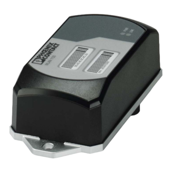
Figure 1-1
FL WLAN 1100
Technical description
7
PHOENIX CONTACT
Advertisement
Table of Contents

Related Manuals for Phoenix Contact FL WLAN 1100


Summary of Contents for Phoenix Contact FL WLAN 1100
- Page 1 Technical description Technical description Unless otherwise expressly stated, all information provided in this user manual always ap- plies to both the FL WLAN 1100 and the FL WLAN 1101. General description Robust, compact WLAN module with integrated antennas: – Turnkey solution with integrated antenna and wireless module in a single device –...
- Page 2 1.2.1 FL WLAN 1100 The FL WLAN 1100 is a WLAN device with access point and client functionality. The device uses the WLAN standard in the license-free 2.4 GHz and 5 GHz bands which are free of charge. It is approved for use in Europe.
- Page 3 Cet équipement doit être installé et utilisé avec un minimum de 20 cm de distance entre la source de rayonnement et votre corps. Ce transmetteur ne doit pas etre place au meme endroit ou utilise simultanement avec un autre transmetteur ou antenne. 107390_en_01 PHOENIX CONTACT...
- Page 4 FL WLAN 1000/2000 Firmware Table 1-1 Firmware version Functions FW 1.0x Initial version Additional information on the latest firmware changes for the respective product can be found in the e-shop at phoenixcontact.com or at phoenixcontact.net/product/2702534. PHOENIX CONTACT 107390_en_01...
-
Page 5: Mounting/Antenna Configuration
Connections and operating elements of the device Mounting holes Marking fields Status and diagnostic LEDs Ethernet connection in RJ45 format with 100 Mbps Connections for supply voltage and one digital input via COMBICON Two integrated WLAN antennas 107390_en_01 PHOENIX CONTACT... -
Page 6: Housing Dimensions
FL WLAN 1100/1101 2.1.1 Housing dimensions The outside dimensions of the FL WLAN 1100 and FL WLAN 1101 devices are 62.8 mm x 36.5 mm x 113.2 mm (width x height x depth). Figure 2-2 Housing dimensions and distances 2.1.2... - Page 7 The device must be connected to ground (functional earth ground) via the metal part of the housing. If this is not possible, ensure a low-resistance ground connection (functional earth ground) for the shielding of the Ethernet cable. 107390_en_01 PHOENIX CONTACT...
-
Page 8: Mounting The Device On A Level Surface
FL WLAN 1100/1101 FL WLAN 1100 and FL WLAN 1101: it is recommended that the base plate of the device is grounded by connecting the mounting screws to a grounded metal surface (functional earth ground/FE). If this is not possible, e.g., because the device is installed on a plastic surface, you must make sure that the Ethernet cable is properly shielded. - Page 9 Mounting/antenna configuration 2.1.3.1 Drill hole template Figure 2-5 Drill hole template (original size) 107390_en_01 PHOENIX CONTACT...
- Page 10 The metal cable feed-through (FL M32 ADAPTER, Order No. 2702544) screws into the M32 in- ternal thread of the FL WLAN 1100 connection dome. The FL WLAN 1100 is therefore sealed to IP54 even outdoors.
- Page 11 2.1.4.3 Mounting taking the internal antennas into consideration The FL WLAN 1100 has two internal antennas which transmit through the plastic housing. This must be taken into consideration when mounting the device: in order to ensure that the WLAN signal can be transmitted via the built-in antennas, the device must not be installed inside control cabinets or other metal housings.
Need help?
Do you have a question about the FL WLAN 1100 and is the answer not in the manual?
Questions and answers