Sierra Wireless AirLink GX400 User Manual
Hspa+
Hide thumbs
Also See for AirLink GX400:
- Hardware user's manual (68 pages) ,
- User manual (48 pages) ,
- Installation manual (6 pages)
Table of Contents
Advertisement
Advertisement
Table of Contents

Related Manuals for Sierra Wireless AirLink GX400


Summary of Contents for Sierra Wireless AirLink GX400
- Page 2 www.usatcorp.com sales@usatcorp.com | 888-550-USAT...
- Page 3 Note: Some airlines may permit the use of cellular phones while the aircraft is on the ground and the door is open. Sierra Wireless AirLink GX400 may be used at this time. The driver or operator of any vehicle should not operate the Sierra Wireless AirLink GX400 while in control of a vehicle.
-
Page 4: Contact Information
This product may contain technology developed by or for Sierra Wireless Inc. This ® product includes technology licensed from QUALCOMM 3G. This product is manufactured or sold by Sierra Wireless Inc. or its affiliates under one or more patents licensed from InterDigital Group. Copyright © 2011 Sierra Wireless. All rights reserved. -
Page 5: Revision History
www.usatcorp.com Preface Revision History Revision Release date Changes number June 2011 GX400 HSPA+ User Guide created. Rev 1.0 Jun.11 sales@usatcorp.com | 888-550-USAT... - Page 6 www.usatcorp.com GX400 HSPA+ User Guide 2140712 sales@usatcorp.com | 888-550-USAT...
-
Page 7: Table Of Contents
www.usatcorp.com Contents Introduction to the GX400 ........11 ACEware™. - Page 8 Activating the AirLink GX400 ........
- Page 9 www.usatcorp.com Contents Inputs, Relay Outputs, and Power Status ......39 Capturing External Events ........39 Digital Input .
- Page 10 www.usatcorp.com GX400 HSPA+ User Guide 2140712 sales@usatcorp.com | 888-550-USAT...
-
Page 11: Introduction To The Gx400
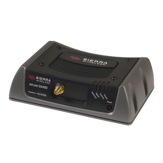
Figure 1-1: AirLink GX400 ALEOS, the embedded core technology of the Sierra Wireless AirLink product, simplifies installation, operation and maintenance of any deployment, and provides an always-on, always-aware intelligent connection for mission-critical applications. -
Page 12: Aceware
Doctor). You can download the applications and their user guides from the Sierra Wireless AirLink Solutions web site: http://www.sierrawireless.com/support. Contact your dealer or Sierra Wireless representative for any further information. Note: ACEview requires the Microsoft .NET Framework v. 2.0 and Microsoft Windows 98, Windows 2000, Windows XP, or later. -
Page 13: Simplified Deployment
www.usatcorp.com Introduction to the GX400 Figure 1-4: ACEmanager Simplified Deployment ACEmanager provides the ability to remotely set up and configure your Sierra Wireless AirLink products. Remote device setup and configuration reduces the deployment timeline of your wireless solution and provides a quicker path to ROI. Templates allow you to easily configure devices in your fleet with identical settings, ensuring a simple, accurate deployment. -
Page 14: Aceview
www.usatcorp.com GX400 HSPA+ User Guide ACEview ACEview is an efficient status and connection monitoring application with a low- profile, easy to read interface. Connecting to Your Cellular Provider When your GX400 is powered on, it automatically searches for cellular service. The GX400 will perform routing for all internet traffic to and from the computers or other end devices. -
Page 15: Communication
www.usatcorp.com Introduction to the GX400 Communication Many of the GSM Networks have been expanded to HSPA+. HSPA+ HSPA+ (High-Speed Packet Access +) is an enhanced version of HSPA cellular technology defined by the 3rd Generation Partnership Project (3GPP) Release 7 UMTS specification for Mobile Terminated Equipment. -
Page 16: Connection Methods
www.usatcorp.com GX400 HSPA+ User Guide Connection Methods You can connect the GX400 to a USB (micro A/B) or an Ethernet (RJ45) port on a computer. When connected to a USB or Ethernet port, the GX400 behaves like a network card. The GX400 is equipped with a USB port which increases the methods by which you can send and receive data. -
Page 17: Gre
Introduction to the GX400 The IPsec architecture model includes the Sierra Wireless AirLink gateway as a remote gateway at one end communicating, through a VPN tunnel, with a VPN gateway at the other end. The remote gateway is connected to a Remote network and the VPN is connected to the Local network. -
Page 18: Documentation
GX400 HSPA+ User Guide The GX400 has an embedded radio module, also made by Sierra Wireless, Inc. There are two firmware programs on the device—one stored on the con- troller board of the GX400 and one on the radio module. -
Page 19: Specifications
www.usatcorp.com 2: Specifications • Interface Port Pin- Outs • Power Connector Features and Benefits • Powered by ALEOS • Embedded Intelligence • Connection Management • IPsec/VPN Firewall • LBS & Events reporting Engines • ACEware interface • Remote Management and Configuration •... -
Page 20: Power Consumption: (@12V Dc)
www.usatcorp.com GX400 HSPA+ User Guide Power Consumption: (@12V DC) • Transmit/Receive (Typical/Max) 230/380 mA • Idle 180 mA • Low Power Mode <50 mA • Input Voltage 9 - 36V DC Standards/Approvals • Carrier specific approvals • • • RoHS Compliant •... -
Page 21: Led Indicators
www.usatcorp.com Specifications LED Indicators • Network • Signal • Activity • Power Interface Port Pin-Outs Serial Port < - > GND (Ground) Unused < - DTR Data Terminal Ready) CTS (Clear to Send) < - Rx (Receive) RTS (Request to Send) - >... - Page 22 www.usatcorp.com GX400 HSPA+ User Guide 2140712 sales@usatcorp.com | 888-550-USAT...
-
Page 23: Installing And Activating Airlink Gx400
• Activating the your cellular provider’s network. AirLink GX400 The AirLink GX400 should be mounted in a position that provides easy access for • Updating AirLink all cabling. Cables should not be bent, constricted, in close proximity to high GX400 Firmware amperage, or exposed to extreme temperatures. -
Page 24: Physical Interfaces
GX400 HSPA+ User Guide Physical Interfaces The AirLink GX400 has the following physical interfaces and connection methods: • Primary Cellular - 50 Ohm SMA • Receive Diversity - 50 Ohm SMA • GPS - 50 Ohm SMA • USB OTG Micro A/B locking •... -
Page 25: Activating The Airlink Gx400
3. Plug the power cable to the power connector on the back panel of the AirLink GX400 - See Connecting to Power on page 27. 4. Connect your computer to the AirLink GX400 with an Ethernet, serial, or USB cable - See Connecting to a Computer or Other Device on page 28. -
Page 26: Configuring Through Acemanager
ACEmanager is a free utility. Follow the steps below to connect to ACEmanager and begin configuring the GX400 device. • Ensure that the AirLink GX400 is properly connected to allow access to the ACEmanager user interface. • Go to: http://192.168.13.31:9191 the first time you connect to ACEmanager. -
Page 27: Gps Antenna
GPS antenna or cable directly to the threaded SMA connector. If you are mounting the AirLink GX400 in a vehicle, the less the cable is wrapped and bound together, the better it will perform. Place it on the roof, on the dash, or on a rear panel where it has a greater than 90°... -
Page 28: Connecting To A Computer Or Other Device
The left LED blinks yellow during activity, and the right LED is Green for 100 Mbps and Orange for 10 Mbps. The Ethernet port of the AirLink GX400 can be connected directly to a computer or other Ethernet device with either a cross- over cable or a straight-through cable. -
Page 29: Serial Port
GX400 operates as a self-powered device: it will not draw any current from the USB. If a Micro-A plug is inserted, the AirLink GX400 can operate in host mode and supply power to the device that is plugged into. At this time, however, USB host capability is a future ALEOS enhancement. -
Page 30: Led Operation
GX400 HSPA+ User Guide LED Operation Four LEDs are visible from the front and top of the AirLink GX400. Labeled (from left to right) Network, Signal, Activity, and Power, each LED can display one of three colors: green, yellow, or red. -
Page 31: Light Patterns
Data Retry, Failed Auth, and Retrying - The Network LED blinks red every 3 seconds. Reset Button The Reset button, located on the right front side of the AirLink GX400, has two primary functions: 1. Reboot the device: Quickly press in and release. - Page 32 www.usatcorp.com GX400 HSPA+ User Guide 2140712 sales@usatcorp.com | 888-550-USAT...
-
Page 33: Configuring The Airlink Gx400
Windows XP. 1. Choose a name and icon for your connection a. Choose a name for your connection, such as AirLink GX400 or Sierra Wireless AirLink Solutions. The name and icon are only for your own reference so you can find the connection at a later date. - Page 34 · Flow Control: Hardware (or None). Figure 4-2: Port Settings at COM1 Properties Tip: If you have configured the AirLink GX400 for settings different than the defaults for Bits per second, Data bits, Parity, and/or Stop bits, you will need to use your changed settings.
- Page 35 Configuring the AirLink GX400 If using Telnet with either Ethernet or USB/net: d. Select TCP/IP (Winsock) for “Connect using”. e. Type in 192.168.13.31 for the Host address. Change the “Port number” to 2332. g. Select OK. 3. You are now connected.
-
Page 36: At Commands
www.usatcorp.com GX400 HSPA+ User Guide Figure 4-4: HyperTerminal: connected a. If you are prompted for a password, enter the default password 12345. Tip: You will not be prompted for a password if you connect using a COM port. b. Type AT and press Enter. You should get a reply of “OK” or “0”. c. - Page 37 “e”. • When you are using a terminal connection, if you enter a command which is recognized by the AirLink GX400, it will respond with “OK”. If the command is not recognized, the response will be “ERROR”. • Those commands applicable only to certain model numbers of the AirLink GX400 will be noted.
- Page 38 www.usatcorp.com GX400 HSPA+ User Guide 2140712 sales@usatcorp.com | 888-550-USAT...
-
Page 39: Inputs, Relay Outputs, And Power Status
1 digital I/O. These may be connected to sensors and switches to monitor status and remotely control equipment. AirLink GX400 board supports a low power timer enable input pin and a digital I/O pin which are connected to the CPU processor. The I/O signal comes in from the power connector, through a PolySwitch resettable fuse, and ties into the CPU pins with protection circuitry. -
Page 40: Digital Output
Low power mode turns off the 1.8V (memory interface) and 1.0V (core) supply voltages connected to the processor to save power. The AirLink GX400 can be configured to switch power modes in response to specific events, such as when the voltage to the device drops below a configured threshold or when ignition is turned off, in order to conserve a vehicle's battery life. -
Page 41: Power Effect On Device State
www.usatcorp.com Inputs, Relay Outputs, and Power Status Power Effect on Device State Once the transition from powered on to low-power mode starts, the device will change state to AT mode. This results in the current mode being gracefully terminated. For the brief period when the device is preparing for low-power mode, the device will remain in AT mode. - Page 42 www.usatcorp.com GX400 HSPA+ User Guide 2140712 sales@usatcorp.com | 888-550-USAT...
-
Page 43: Regulatory Information
www.usatcorp.com Regulatory Information 6: Regulatory Information Federal Communications Commission Notice (FCC United States) Electronic devices, including computers and wireless devices, generate RF energy incidental to their intended function and are therefore subject to FCC rules and regulations. This equipment has been tested to, and found to be within the acceptable limits for a Class A device. -
Page 44: Antenna Considerations
A minimum separation distance of 20 cm must be maintained between the aanenna(s) used for this transmitter and all personnel. Sierra Wireless hereby declares that the AirLink GX400 devices conform to all the essential requirements of Directive 1999/5/EC. This equipment has been tested to, and found to be acceptable, within the acceptable limits for a Class A device. -
Page 45: Weee Notice
UB11 1BD England WEEE Notice If you purchased AirLink GX400 in Europe, please return it to your dealer or supplier at the end of its life. WEEE products may be recognized by their wheeled bin label on the product label. - Page 46 www.usatcorp.com GX400 HSPA+ User Guide 2140712 sales@usatcorp.com | 888-550-USAT...
- Page 47 www.usatcorp.com sales@usatcorp.com | 888-550-USAT...
Need help?
Do you have a question about the AirLink GX400 and is the answer not in the manual?
Questions and answers