OHAUS T51XW Quick Start Manual
Hide thumbs
Also See for T51XW:
- Instruction manual (64 pages) ,
- User manual (61 pages) ,
- Service manual (42 pages)
Advertisement
Quick Links
Quick Start Guide
ASSEMBLY
Both the T51P and T51XW connect to a base scale through a Load Cell Cable that connects to
the Indicator's Main Printed Circuit Board (PCB). Each model has a mounting bracket that can
be attached to a column mount bracket or a wall mount. To remove the mounting bracket,
remove the threaded knobs, holding the Indicator by hand.
ELECTRICAL SHOCK HAZARD. REMOVE ALL POWER CONNECTIONS TO THE
INDICATOR BEFORE MAKING INTERNAL CONNECTIONS.
The process of opening the Housing varies slightly for each model:
T51P:
1. Remove the four Phillips head screws
from the rear housing.
2. Open the housing; disconnect the
ribbon cable from the top of the PCB.
The T51's Main PCB, with connectors, jumpers, terminals and switches is shown below.
Power Supply
connector
Recharge
option-T51P
(opposite side)
Alternate
Load Cell
Terminal J4
Sense
Jumper W1
Jumper Connections:
For a 4-wire load cell with no sense wires, short Jumpers W1 and W2.
For a 6-wire load cell that includes sense wires, open Jumpers W1 and W2.
For load cells with an extra ground shield wire, connect the shield to the center position (GND).
+EXC
+SIG
-SIG
+SENS
GND
Load Cell wiring.
Ohaus Corporation www.ohaus.com
CAUTION:
Sense
Jumper W2
Load Cell
Connector Plug
Printed Circuit Board (PCB), T51 Indicator.
Pin
Connection
J4-1
J4-2
J4-3
J4-4
-EXC
J4-5
-SENS
J4-6
J4-7
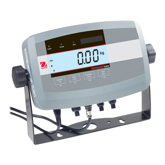
T51 Indicators
T51XW:
1. Remove the four hex head screws from
the rear housing.
2. Open the housing by carefully pulling
the top of the front housing forward.
Security Switch
SW2
External Input
Terminal Block
+Excitation
+Sense
+Signal
GND
–Signal
–Sense
–Excitation
i
COM2
Connector J8
(Optional:
RS232 or
RS422/485)
RS232
Terminal J7
(T51XW only)
Battery
connector J2
(T51P only)
RS232 Pin Connector
(T51P only)
Open/shorted jumpers.
T51 Indicators Quick Start Guide
Advertisement

Subscribe to Our Youtube Channel
Related Manuals for OHAUS T51XW


Summary of Contents for OHAUS T51XW
- Page 1 T51 Indicators ASSEMBLY Both the T51P and T51XW connect to a base scale through a Load Cell Cable that connects to the Indicator’s Main Printed Circuit Board (PCB). Each model has a mounting bracket that can be attached to a column mount bracket or a wall mount. To remove the mounting bracket, remove the threaded knobs, holding the Indicator by hand.
- Page 2 Aborts a calibration in Rejects the current setting on Decrements the value. progress. the display and advances to the next available setting. Increments the value. T51 Indicators Quick Start Guide Ohaus Corporation www.ohaus.com...
- Page 3 Off, On Percent Off, On When modes are On, choose by toggling through available options Dynamic Off, Manual by pressing Mode. Checkweigh Off, On For details on various application modes, see Instruction Manual. Ohaus Corporation www.ohaus.com T51 Indicators Quick Start Guide...
- Page 4 Lock Tare Lock COM2 Lock Menu Lock GMP End Lock Key Lock I-O End Lock Menu Note: For Relay Option and RS 485/422 Option Kits, see instruction manuals at www.Ohaus.com. *80253034* P/N 80253034 T51 Indicators Quick Start Guide Ohaus Corporation www.ohaus.com...
Need help?
Do you have a question about the T51XW and is the answer not in the manual?
Questions and answers