Table of Contents
Advertisement
Available languages
Available languages
Quick Links
Advertisement
Chapters
Table of Contents
Troubleshooting

Related Manuals for Olimpia splendid Unico Boiler


Summary of Contents for Olimpia splendid Unico Boiler
- Page 2 8 12 8 10 9 11 L max tubazioni / Pipes max L / L max tubes / L max. Rohrleitungen / L máx. tuberías: 10 m.
- Page 3 UNICO BOILER...
- Page 5 UNICO BOILER...
- Page 6 LED D LED C LED B LED A...
- Page 7 UNICO BOILER...
- Page 9 UNICO BOILER MASTER UNICO BOILER WALL UNICO BOILER...
- Page 11 UNICO BOILER...
- Page 12 D1 D2 D3 K4 L1 T1 S2 S3 S5 S4 AUTO AUTO...
-
Page 13: Table Of Contents
2.1.10 Allacciamento elettrico UNICO BOILER MASTER ......................19 2.1.11 Configurazione installazione alta/bassa ..........................20 2.1.12 Prove di funzionamento e diagnosi di eventuali anomalie UNICO BOILER MASTER ............20 2.1.13 Evacuazione dell’acqua di condensa in caso di emergenza ....................22 MODALITÀ D’INSTALLAZIONE UNICO BOILER WALL ......................... 22 2.2.1... -
Page 14: Generalità
Documento riservato ai termini di legge con divieto di riproduzione o di trasmissione a terzi senza esplicita autorizzazione della ditta OLIMPIA SPLENDID. Le macchine possono subire aggiornamenti e quindi presentare particolari diversi da quelli raffigurati, senza per questo costituire... -
Page 15: Avvertenza
Il climatizzatore deve essere utilizzato esclusivamente per produrre aria calda o fredda (a scelta) con il solo scopo di rendere confortevole la temperatura nell’ambiente. Un uso improprio dell’ apparecchiatura con eventuali danni causati a persone, cose o animali sollevano l’OLIMPIA SPLENDID da ogni responsabilità. -
Page 16: Immagazzinamento
3 giorni dal ricevimento gli eventuali danni allo spedizioniere a mezzo raccomandata r.r. presentando documentazione fotografica. Analoga informazione inviarla tramite fax anche a OLIMPIA SPLENDID. Nessuna informazione concernente danni subiti potrà essere presa in esame dopo 3 giorni dalla consegna. -
Page 17: Installazione
La mancata applicazione delle norme indicate, che può causare mal funzionamento delle apparecchiature, sollevano la ditta OLIMPIA SPLENDID da ogni forma di garanzia e da eventuali danni causati a persone, animali o cose. É importante che l’impianto elettrico sia a norma, rispetto ai dati riportati nella scheda tecnica e sia provvisto di una buona messa a terra. -
Page 18: Predisposizione Dello Scarico Condensa
Predisposizione dello scarico condensa (figg. 8, 9, 10) Alla unità UNICO BOILER MASTER deve essere collegato il tubo di scarico condensa (fornito a corredo) da innestare nell’apposito bocchettone (fig. 8 rif. A) presente sul retro della macchina (togliere il tappo presente B); un’elettrovalvola garantirà il deflusso della condensa dalla vaschetta interna quando viene raggiunto il livello massimo. -
Page 19: Predisposizione Fori Sulla Macchina
2.1.10 Allacciamento elettrico UNICO BOILER MASTER (figg. 19, 20, 21) L’apparecchio è dotato di un cavo di alimentazione con spina (collegamento di tipo Y). Nel caso di utilizzo di una presa di corrente in prossimità... -
Page 20: Configurazione Installazione Alta/Bassa
CONTROLLO ELETTRONICO. 2.1.12 Prove di funzionamento e diagnosi di eventuali anomalie UNICO BOILER MASTER (fig. 24) Il climatizzatore è in grado di eseguire un breve ciclo di autodiagnosi per verificare il normale funzionamento dei componenti interni e durante il quale è possibile eseguire la configurazione del controllo elettronico a seconda che l’installazione dell’apparecchiatura sia stata realizzata nella parte alta (a soffitto) o bassa (a pavimento) della parete. - Page 21 Nel caso di malfunzionamento della unità UNICO BOILER WALL, è possibile far funzionare temporaneamente il solo UNICO BOILER MASTER. Per cancellare lo stato di allarme ed abilitare la sola unità UNICO BOILER MASTER è necessario: rimuovere la tensione di rete da entrambe le unità, attendere alcuni secondi, ricollegare alla linea di alimentazione la sola unità UNICO BOILER MASTER.
-
Page 22: Evacuazione Dell'acqua Di Condensa In Caso Di Emergenza
La mancata applicazione delle norme indicate, che può causare mal funzionamento delle apparecchiature, sollevano la ditta OLIMPIA SPLENDID da ogni forma di garanzia e da eventuali danni causati a persone, animali o cose. É importante che l’impianto elettrico sia a norma, rispetti i dati riportati nella scheda tecnica e sia provvisto di una buona messa a terra. -
Page 23: Collegamenti Frigoriferi
Eseguire la cartellatura sulle estremità dei tubi, utilizzando l’apposito utensile, in modo impeccabile, senza rotture, incrinature o sfaldature (fig. 30 B). Lubrificare il filetto dell’attacco con olio per refrigerante (NON UTILIZZARE NESSUN ALTRO TIPO DI LUBRIFICANTE). Avvitare manualmente il dado del tubo sulla filettatura dell’attacco. UNICO BOILER... -
Page 24: Prove E Verifiche
C Foro di carico D Valvola principale Legenda figura 32: A Gruppo manometrico B Eventuale vacuometro C Pompa del vuoto D Rubinetto del tubo flessibile (aperto) E Raccordo di servizio F Tubo del gas G Tubo del liquido H UNICO BOILER MASTER... -
Page 25: Collegamnto Idraulico
Norme di istallazione – Collegamentoidraulico) Collegare l’ingresso (fig. 4 rif. 10) e l’uscita (fig. 4 rif. 11) acqua di UNICO BOILER WALL con tubi flessibili e raccordi resistenti, oltre che alla pressione d’esercizio alla temperatura dell’acqua calda che normalmente può raggiungere e anche superare gli 80°C. -
Page 26: Linea Comunicazione Unico Boiler Master E Unico Boiler Wall
Temperature di esercizio minime in riscaldamento DB -15°C Dall’unità UNICO BOILER WALL posizionare il cavo di comunicazione (fig. 36) fino a raggiungere la morsettiera dell’unità UNICO BOILER MASTER. Il cavo di comunicazione fra le due unità deve essere del tipo schermato con le seguenti caratteristiche: n°2 poli più... -
Page 27: Consegna Dell'impianto
(fig. 24 rif. H). In questo modo viene resettata la segnalazione relativa alla necessità di pulizia filtro. MANUTENZIONE PERIODICA UNICO BOILER WALL Per ottenere il buon rendimento dell’ apparecchio è opportuno procedere alla disincrostazione della resistenza posizionata sotto il termostato di sicurezza bipolare (fig. -
Page 28: Uso E Manutenzione (Parte Utente)
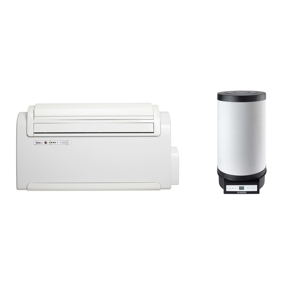
Componenti del sistema (fig.41) Il sistema è composto da un’unità UNICO BOILER WALL (1), da un’unità UNICO BOILER MASTER (8) contenente il compressore, il ventilatore, lo scambiatore di calore e dal telecomando (9) per la gestione ed il controllo delle varie funzioni (vedi par. 3.3.2). -
Page 29: Inserimento Batterie
La macchina UNICO BOILER MASTER è dotata di un interruttore di alimentazione (fig. 42 rif. A) posizionato sotto la protezione inferiore (fig. 42 rif. B); per funzionare deve essere in posizione “I”. -
Page 30: Funzionamento In Raffreddamento
L’avviamento del compressore è visibile dall’illuminazione del relativo LED verde che si trova sulla consolle. AVVERTENZE: è possibile che la erogazione di aria calda sia temporaneamente sospesa al fine di favorire la produzione di acqua calda se e solo nella eventualità di UNICO BOILER WALL con abilitata la funzione Turbo1 e/o Turbo2 (Fig.43). -
Page 31: Impostazione Dei Programmi Di Funzionamento
In particolare, ogni volta che si preme il pulsante T11 (Attivazione dei programmi) la situazione cambia come segue: Attivazione del solo 1° Programma. Attivazione del solo 2° Programma. Attivazione del 1° e del 2° Programma. Disattivazione di entrambi i programmi. UNICO BOILER... -
Page 32: Resettaggio Di Tutte Le Funzioni Del Telecomando
Accensione/Spegnimento dell’apparecchio Tramite il pulsante T1 (Fig.43) è possibile spegnere (Stand-by) o accendere UNICO BOILER WALL. Alla sua accensione, la unità è sempre in funzione riscaldamento (icona S2 attiva) e provvede autonomamente ad attivare il riscaldamento dell’acqua ogni qual volta la differenza tra la temperatura desiderata e visualizzata a display (fig.4BIS+4TRIS) differisce dalla temperatura dell’acqua all’interno dell’accumulo. -
Page 33: Aspetti Funzionali Da Non Interpretare Come Inconvenienti
Durante il funzionamento in riscaldamento di UNICO BOILER MASTER l’erogazione aria calda può avvenire qualche minuto dopo l’attivazione del compressore. Durante il funzionamento di UNICO BOILER MASTER in riscaldamento o ventilazione, la erogazione d'aria calda può essere temporaneamente sospesa (per dettagli vedere paragrafi relativi ad uso e manutenzione par. 3.3.7 e 3.3.8). -
Page 34: Dati Tecnici
2 x 0,5 mm schermato, lunghezza massima 15 m - Cavo di alimentazione UNICO BOILER WALL H05VV-F 3 x 1,5 mm CONTENUTO ACQUA SERBATOIO 50 LITRI PRESSIONE MASSIMA DI LAVORO LATO ACQUA UNICO BOILER MASTER PS 600 kPa (0,6 MPa) - Page 35 WARNINGS ...................................... 49 3.1.1 Components of the system ..............................49 3.1.2 Description of the warning panel of UNICO BOILER MASTER and UNICO BOILER WALL ..........49 MANAGEMENT OF UNICO BOILER MASTER UNITS WITH REMOTE CONTROL ..............49 3.2.1 Remote control ................................... 49 3.2.2...
-
Page 36: General
GENERAL SYMBOLS The pictograms shown in the next chapter provide the information necessary for correct use of the appliance in a rapid and unmistakable way. 1.1.1 Editorial pictograms Service Refers to situations in which you should inform the SERVICE department in the company: CUSTOMER TECHNICAL SERVICE. Index Paragraphs marked with this symbol contain very important information and recommendations, particularly as regards safety. -
Page 37: Warning
The air-conditioner should be used for the exclusive purpose of producing hot or cool air (on demand) for the sole purpose of obtaining a comfortable temperature in the room. Improper use of the equipment, which may cause injury/damage to persons, property or animals, relieves OLIMPIA SPLENDID of any liability. -
Page 38: Storage
3 days of receipt of the goods and enclosing photographic evidence. Send the same information by fax to OLIMPIA SPLENDID. No complaints will be accepted if made more than 3 days after the delivery of the goods. -
Page 39: Installation
OLIMPIA SPLENDID of any form of guarantee and liability for damages to persons, animals or property. The electrical system must comply with the regulations and rating data in the technical sheet, with good grounding. -
Page 40: Preparing The Condensate Discharge
Preparing the condensate discharge (figg. 8, 9, 10) The condensate discharge pipe (supplied) must be connected to the UNICO BOILER MASTER by coupling it with the specific vent (fig. 8 ref. A) that is on the back of the machine (remove cap B). When the max level is reached, a solenoid valve ensures the condensate will flow out from the internal tray. -
Page 41: Preparing The Holes On The Machine
(minimum cross-section of the cable must be 1.5 mm The appliance is powered exclusively through a socket that is compatible with the plug supplied. WARNING: Any replacement of the power cable must be carried out solely by Olimpia Splendid technical support or by similarly qualified personnel. -
Page 42: Top/Bottom Installation Configuration
2.1.11 UNICO BOILER MASTER CONFIGURATION, TOP/BOTTOM INSTALLATION (FIGS. 22, 23) This unit may be installed either at the bottom of the wall (adjacent to the floor) or at the top (adjacent to the ceiling). The air jet can be modified to optimize air distribution and room well-being by changing the position of the air outlet flap. -
Page 43: Evacuating Condensate Water During An Emergency
If the UNICO BOILER WALL unit malfunctions, the UNICO BOILER MASTER can be run temporarily on its own. To clear the alarm status and enable the UNICO BOILER MASTER unit on its own, proceed as follows: cut the mains voltage to both units, wait a few seconds, and then reconnect the power line to the UNICO BOILER MASTER unit only. -
Page 44: Choice Of Position For Unico Boiler Wall Unit
Drill the hole at the centre of the site of installation using an 8-10 mm bit and tilting it downward towards the outside by 5%. Finish the hole with a 60 mm auger. Fit the coolant lines and the communication cable with the UNICO BOILER MASTER unit through the hole. 2.2.5 Installation of unit Hang the boiler onto the hooks on the wall as described in paragraph 2.2.3 on the top wall plugs and fix the bottom bracket... -
Page 45: Cooler Connection
Any use of fluorinated gas in this product must comply with Regulation (EU) 517/2014 and any local rules that apply. No additional filling is needed in the installation phase. Do not exceed the load stated on the data plate. UNICO BOILER... -
Page 46: Tests And Inspection
– Water connection’) Connect the water inlet (fig. 4 ref. 10) and outlet (fig. 4 ref. 11) of the UNICO BOILER WALL with hoses and fittings that will withstand not only the working pressure but also the hot water temperatures, which can regularly reach and exceed 80°C. Therefore, do not use materials that cannot withstand such high temperatures. - Page 47 Then, the red LED and display icon flash. The electric HEATER1 heating element output is activated for a few seconds if enabled. Should the UNICO BOILER WALL block and signal an error (as indicated in the following table), specify to the service centre the error message shown on the display (fig.
-
Page 48: Unico Boiler Master And Unico Boiler Wall Communication Line
UNICO BOILER MASTER PERIODIC MAINTENANCE The air conditioner that you have purchased has been designed to reduce routine maintenance operations to a minimum. These operations involve solely the cleaning operations outlined below: Cleaning or washing of the ambient air filter every 2 weeks or every time the relative red LED lights up (this can be done by the user, see user manual). -
Page 49: Use And Maintenance (User Part)
Components of the system (fig. 41) The system is made up of a UNICO BOILER WALL unit (1) and a UNICO BOILER MASTER unit (8) containing the compressor, the fan, the heat exchanger and the remote control (9) for management and control of the various functions (see sect. 3.3.2). -
Page 50: Fitting The Batteries
The UNICO BOILER MASTER machine is fitted with a power switch (fig. 42 ref. A) located below the lower safety guard (fig. 42 ref. B); to run it must be in “I” position. -
Page 51: Well-Being Key (Automatic Operating)
Well-being key (automatic operating) When button T2 is pressed, UNICO BOILER MASTER will automatically arrange to obtain optimal comfort in the room that is conditioned. In relation to the internal temperature of the room, the conditioner will automatically set the operating mode (cooling, ventilation or, if available, heating), the temperature and the fan speed. -
Page 52: Night Well-Being Key
3.3.17 Managing the unit if the remote control is not available UNICO BOILER MASTER Should the remote control be lost, the batteries flat or if it is faulty, the appliance may be operated only in automatic mode by pressing the micro switch positioned underneath the hole located on the console by means of a pointy object. -
Page 53: Energy Saving Advice
BACKUP function If the UNICO BOILER MASTER is in Dehumidification mode or stopped in the alarm condition, or if there is a break in the line of communication, hot water production is in any case guaranteed through the UNICO BOILER WALL electric heating element. -
Page 54: Troubleshooting
2 x 0.5 mm2 screened, maximum length 15 m - UNICO BOILER WALL power supply cable H05VV-F 3 x 1,5 mm WATER TANK CAPACITY 50 LITRES MAXIMUM WORKING PRESSURE ON WATER SIDE FOR UNICO BOILER MASTER PS 600 kPa (0.6 MPa) - Page 55 MODE D’EMPLOI ET ENTRETIEN (PARTIE UTILISATEUR) ......................70 AVERTISSEMENTS ...................................70 3.1.1 COMPOSANTS DU SYSTEME ............................70 3.1.2 Description de la console d’indication UNICO BOILER MASTER et UNICO BOILER WALL ..........70 GESTION DES APPAREILS UNICO BOILER MASTER AVEC TÉLÉCOMMANDE ................70 3.2.1 Télécommande ..................................70 3.2.2 Mise en place des piles ................................71...
-
Page 56: Generalites
Document réservé aux termes de la loi avec interdiction de reproduction ou de transmission à tiers sans l’autorisation expresse de la société OLIMPIA SPLENDID. Les machines peuvent subir des mises à jour et par conséquent présenter des éléments différents de ceux qui sont représentés,... -
Page 57: Avertissement
(buanderies, serres, etc.), ou dans des locaux où se trouvent d’autres machines produisant une importante source de chaleur. En cas de remplacement de composants, utiliser exclusivement des pièces de rechange originales OLIMPIA SPLENDID. IMPORTANT! Afin de prévenir tout risque d’électrocution, il est indispensable de couper le courant au disjoncteur principal avant d’effectuer des branchements électriques et toute opération d’entretien sur les appareils. -
Page 58: Stockage
3 jours à partir de la réception par lettre recommandée avec accusé de réception en présentant la documentation photographique. Envoyer aussi par fax cette même information à OLIMPIA SPLENDID. Aucune information concernant les dommages subis ne pourra être prise en considération au-delà de 3 jours après la livraison. -
Page 59: Installation
Le non-respect de l’application des normes indiquées, qui peut entraîner un mauvais fonctionnement des appareillages, dégage la société OLIMPIA SPLENDID de toute forme de garantie et des éventuels dommages causés à des personnes, animaux ou biens. -
Page 60: Préparation De L'évacuation Des Condensats
Préparation de l’évacuation des condensats (figg. 8, 9, 10) A l’unité UNICO BOILER MASTER doit être branché le tube d’évacuation des condensats (fourni), qui doit être raccordé au goulot prévu à cet effet (fig. 8 réf. A) présent à l’arrière de la machine (enlever le bouchon présent B); une électrovalve assurera l’écoulement des condensats dans le bac quand le niveau maximal est atteint. -
Page 61: Exécution Des Trous Sur L'appareil
AVERTISSEMENT : Le remplacement éventuel du cordon d’alimentation doit être effectué exclusivement par le service technique Olimpia Splendid ou par du personnel ayant une qualification similaire. AVERTISSEMENT : Il faut prévoir sur le réseau d’alimentation de l’appareil un dispositif de déconnexion omnipolaire approprié... -
Page 62: Configuration Installation Haute/Basse
SORTIE D’AIR DOIT CORRESPONDRE LA MODIFICATION CORRESPONDANTE DE LA CONFIGURATION ELECTRONIQUE. 2.1.12 Tests de fonctionnement et diagnostic d’anomalies éventuelles UNICO BOILER MASTER (fig.24) Le climatiseur est en mesure d’effectuer un court cycle d’autodiagnostic pour contrôler le bon fonctionnement des composants internes et pendant lequel il est possible d’effectuer la configuration du contrôle électronique selon que l’installation de l’appareil... - Page 63 En cas de dysfonctionnement de l’unité UNICO BOILER WALL, il est possible de faire fonctionner temporairement le seul UNICO BOILER MASTER. Pour éliminer l’état d’alarme et activer la seule unité UNICO BOILER MASTER, il est nécessaire : de couper la tension électrique des deux unités, d’attendre quelques secondes, de rebrancher à...
-
Page 64: Evacuation Des Condensats En Cas D'arrêt D'urgence
Faire le trou au centre de la position avec un foret de 8-10 mm et une inclinaison vers l’extérieur de 5%. Procéder ensuite au perçage définitif avec un foret pour carottage guidé de 60 mm. Insérer dans l’orifice les lignes du réfrigérant et le câble de communication avec l'unité UNICO BOILER MASTER. 2.2.5 Montage de l’unité... -
Page 65: Branchements Frigorifiques
Toute utilisation du gaz fluoré dans le présent produit doit être conforme au règlement UE 517/2014 et aux éventuelles normes locales applicables. En phase d’installation, une charge supplémentaire n’est pas nécessaire. Ne pas dépasser la charge indiquée sur la plaque signalétique. UNICO BOILER... -
Page 66: Essais Et Vérifications
C Orifice de remplissage D Valve principale Légende figure 32: A Groupe manométrique B Vacuomètre éventuel C Pompe à vide D Robinet du tube flexible (ouvert) E Raccord de service F Tube du gaz G Tube du liquide H UNICO BOILER MASTER... -
Page 67: Branchement Eau
Branchement hydraulique) Brancher l’entrée (fig. 4 réf. 10) et la sortie (fig. 4 réf. 11) eau de UNICO BOILER WALL au moyen de tubes flexibles et de raccords résistants, outre qu’à la pression de service, à la température de l’eau chaude qui, normalement, peut atteindre voire dépasser les 80°C. Par conséquent, ne pas utiliser les matériaux qui ne résistent pas à... -
Page 68: Ligne De Communication Unico Boiler Master Et Unico Boiler Wall
Températures minimales en chauffage DB -15°C Depuis l’unité UNICO BOILER WALL, placer le câble de communication (fig. 36) jusqu’à atteindre la boîte à bornes de l’unité UNICO BOILER MASTER. Le câble de communication entre les deux unités doit être du type blindé avec les caractéristiques suivantes: 2 pôles + blindage... -
Page 69: Livraison De L'installation À L'utilisateur
(fig. 24 réf. H). De cette façon le signal relatif à la nécessité de nettoyage du filtre est réarmé. MAINTENANCE PERIODIQUE UNICO BOILER WALL Pour obtenir un bon rendement de l’appareil, il convient de procéder au détartrage de la résistance placée sous le thermostat de sécurité... -
Page 70: Mode D'emploi Et Entretien (Partie Utilisateur)
Micro-touche de service uniquement sur l’unité. 3.1.3 Description de la console de contrôle UNICO BOILER WALL (fig. 43) LED rouge allumée indique que le chauffage de l’eau est en cours (si elle est allumée clignotante, cela indique que la fonction de... -
Page 71: Mise En Place Des Piles
La machine UNICO BOILER MASTER est dotée d’un interrupteur d’alimentation (fig. 42 réf. A) placé sous la protection inférieure (fig. 42 réf. B) ; pour fonctionner, il doit être en position “I”. -
Page 72: Allumage/Extinction De L'appareil
Touche bien-être (fonctionnement automatique) En appuyant sur le bouton T2, l’UNICO BOILER MASTER se prépare automatiquement de façon à obtenir dans la pièce climatisée un confort optimal. En fonction de la température interne de la pièce, le climatiseur règle automatiquement le mode de fonction- nement (climatisation, ventilation ou, s’il est prévu, chauffage), la température et la vitesse de ventilation. -
Page 73: Contrôle De La Direction Du Flux D'air
À l’aide de la touche basculante T7 augmenter ou diminuer l’indication de l’heure à laquelle on souhaite que l’appareil se désactive avec le 2e programme. Chaque fois qu’on appuie sur une extrémité de la touche basculante, l’indication de l’heure UNICO BOILER... -
Page 74: Activation Et Désactivation Des Programmes De Fonctionnement
Allumage/extinction de l’appareil Au moyen du bouton T1 (Fig. 43), il est possible d’éteindre (Stand-by) ou d’allumer UNICO BOILER WALL. A son allumage, l’unité est toujours en fonction chauffage (icône S2 active) et active de façon autonome le chauffage de l’eau chaque fois que la différence entre la température souhaitée et affichée sur le dispositif d’affichage (fig. -
Page 75: Diagnostic Des Inconvenients
Dans la logique de fonctionnement de l’appareil, il a été prévu un retard entre un arrêt du compresseur et son redémarrage, de façon à protéger le compresseur contre les activations trop fréquentes. Pendant le fonctionnement en chauffage de l’UNICO BOILER MASTER, la distribution d’air chaud peut avoir lieu quelques minutes après l’activation du compresseur. -
Page 76: Données Techniques
2 x 0,5 mm2 blindé, longueur maximale 15 m - Câble d’alimentation UNICO BOILER WALL H05VV-F 3 x 1,5 mm CONTENANCE DU RÉSERVOIR D’EAU 50 LITRES PRESSION MAXIMALE DE SERVICE COTE EAU UNICO BOILER MASTER PS 600 kPa (0,6 MPa) - Page 77 BEDIENUNG UND WARTUNG (anwenderseitig) ..........................92 WARNHINWEISE ....................................92 3.1.1 Systemkomponenten ................................92 3.1.2 Beschreibung der Anzeigekonsole UNICO BOILER MASTER und UNICO BOILER WALL ..........92 STEUERUNG DER GERÄTE UNICO BOILER MASTER MIT FERNBEDIENUNG ................. 92 3.2.1 Fernbedienung ..................................92 3.2.2 Einlegen der Batterien ................................
-
Page 78: Allgemeines
Informationen. Dokument mit Eigentumsvorbehalt im Sinne des Gesetzes mit dem Verbot der Reproduktion oder Weitergabe an Dritte ohne ausdrückliche Genehmigung de Firma OLIMPIA SPLENDID. Die Maschinen können Aktualisierungen unterliegen und Teile aufweisen, die von den dargestellten verschieden sind, ohne dass... -
Page 79: Hinweis
Die Klimaanlage darf ausschließlich dafür verwendet werden, warme oder kalte Luft (nach Wahl) zu produzieren; ihr einziger Verwendungszweck ist der, die Raumtemperatur angenehm zu temperieren. OLIMPIA SPLENDID übernimmt keinerlei Verantwortung für Schäden, die durch zweckentfremdeten Gebrauch der Anlage an Personen, Sachen oder Tieren entstehen. -
Page 80: Einlagerung
Stellen Sie sicher, dass keine Komponenten Transportschäden aufweisen. Benachrichtigen Sie bei Schäden den Spediteur innerhalb von 3 Tagen per Einschreiben mit Rückschein und Vorlage der Fotodokumentation. Senden Sie die analoge Information auch per Fax an OLIMPIA SPLENDID. Nach Ablauf von 3 Tagen ab der Auslieferung können keine Informationen hinsichtlich davongetragener Schäden berücksichtigt werden. -
Page 81: Installation
Betriebsleistungen erzielen zu können. Die Nichtbeachtung der angeführten Vorschriften kann zu Funktionsstörungen der Anlage führen und enthebt die Firma OLIMPIA SPLENDID von jeder Pflicht zur Garantieleistung und von der Verantwortung für eventuelle Schäden an Personen, Tieren oder Sachen. -
Page 82: Ausführung Des Kondenswasserabflaufs
Ausführung des Kondenswasserabflaufs (Abb. 8, 9, 10) An die Einheit UNICO BOILER MASTER ist der (mitgelieferte) Kondenswasserabflussschlauch anzuschließen, indem er in den vorgesehenen Stutzen (Abb. 8 Pos. A) auf der Rückseite des Gerätes eingeführt wird (entfernen Sie den vorgesehenen Stopfen B). -
Page 83: Montage Der Luftleitkanäle Und Außenroste
-austrittsleitungen, keine Schlitze gebildet haben (die als Isolierung dienende Dichtung muss gut an der Wand anliegen). 2.1.10 Elektrischer Anschluss UNICO BOILER MASTER (Abb. 19, 20, 21) Das Gerät ist mit einem Stromkabel mit Strecker ausgestattet (Anschluss vom Typ Y). Bei Verwendung einer Steckdose in der Nähe des Geräts muss nur der Stecker eingefüh rt werden. -
Page 84: Umstellung Von Truhen - Auf Wandgerät
SIND VOR DEM ELEKTRISCHEN ANSCHLUSS AUCH DIE FOLGENDEN ANWEISUNGEN AUFMERKSAM DURCHZULESEN. 2.1.11 Konfiguration UNICO BOILER MASTER Installation oben/unten (Abb. 22, 23) Das Gerät kann sowohl als Truhengerät (in Bodennähe) als auch als Wandgerät (in Deckennähe) installiert werden. Zur Optimierung der Luftverteilung und des Raumkomforts kann der Luftstrom durch Umstellen der Luftaustrittsklappe verändert werden. -
Page 85: Funktionstests Und Diagnose Eventueller Störungen Unico Boiler Master
2.1.12 Funktionstests und Diagnose eventueller Störungen UNICO BOILER MASTER (Abb. 24) Das Klimagerät ist in der Lage, einen kurzen Selbstdiagnosezyklus durchzuführen, um den normalen Betrieb der inneren Kompo- nenten zu überprüfen. Während dieses Zyklus ist die Ausführung der Konfiguration der elektronischen Steuerungen je nachdem, ob die Installation des Geräts im oberen Bereich (an der Decke) oder unteren Bereich der Wand (am Fußboden) realisiert wurde,... -
Page 86: Ableitung Des Kondenswassers Im Notfall
Bei Funktionsstörungen der Einheit UNICO BOILER WALL ist es möglich, vorübergehend nur die Einheit UNICO BOILER MASTER zu betreiben. Zum Löschen des Alarmstatus und zur Aktivierung nur der Einheit UNICO BOILER MASTER ist wie folgt vorzugehen: Nehmen Sie die Netzspannung von beiden Einheiten weg, warten Sie einige Sekunden und schließen Sie die Versorgungsleitung nur der Einheit UNICO BOILER MASTER wieder an. -
Page 87: Bohrung Für Das Durchführen Der Rohre
Breitkopf-Bohrerspitze (60 mm) aufbohren. Führen Sie die Kühlmittelleitungen und das Kabel zur Kommunikation mit der Einheit UNICO BOILER MASTER in die Öffnung. 2.2.5 Montage der Einheit Hängen Sie den Boiler wie im Abschnitt 2.2.3 (obere Dübel) beschrieben in den an der Wand vorbereiteten Haken ein und befestigen Sie den unteren Bügel mit Unterlegscheibe und Mutter. -
Page 88: Überprüfungen
WICHTIG: Die Rohre dürfen ausschließlich mit einem Rohrschneider (Abb. 28) zugeschnitten werden. Der Schnitt ist langsam auszuführen, damit das Rohr nicht gequetscht wird. AUF KEINEN FALL DARF EINE NORMALE SÄGE VERWENDET WERDEN, iRohr als auch in den Kreislauf der Anlage eindringen und die Komponenten ernsthaft beschädigen könnten (Abb. -
Page 89: Wasseranschluss
Installationsvorschriften – Wasseranschluss) Schließen Sie den Wassereinlauf (Abb. 4 Pos. 10) und den Abfluss (Abb. 4 Pos. 11) des UNICO BOILER WALL mit Schläuchen und Fittings an, die sowohl den Betriebsdruck als auch die Temperatur des heißen Wassers, die auch 80°C übersteigen und überschreiten kann. Verwenden Sie keine Materialien, die bei solchen Temperaturen nicht beständig sind. -
Page 90: Kommunikationsleitung Unico Boiler Master Und Unico Boiler Wall
Minimale Betriebstemperaturen im Heizmodus DB -15°C Positionieren Sie ausgehend von der Einheit UNICO BOILER WALL das Kommunikationskabel (Abb. 36) bis zum Erreichen der Einheit UNICO BOILER MASTER. Das Kommunikationskabel zwischen den beiden Einheiten muss vom abgeschirmten Typ sein und folgende Eigenschaften aufweisen. -
Page 91: Reinigung Des Luftfilters
Gegenstand kurz den Mikrotaster auf der Anzeigekonsole (Abb. 24 Pos. H). Auf diese Weise wird die Meldung bezüglich der Notwendigkeit der Filterreinigung zurückgesetzt. REGELMÄSSIGE WARTUNG DES UNICO BOILER WALL Zur Gewährleistung eines guten Wirkungsgrades des Gerätes sollte der unter dem zweipoligen Sicherheitsthermostat (Abb. 4 Pos. -
Page 92: Bedienung Und Wartung (Anwenderseitig)
Das Gerät darf nicht in Räumen installiert werden, in denen sich explosive Gase bilden oder in denen Feuchtigkeits- und Temperaturwerte, die die in der Installationsanleitung angegebenen Grenzwerte überschreiten, vorhanden sind. Den Luftfilter UNICO BOILER MASTER, wie im entsprechenden Kapitel beschrieben, in regelmäßigen Zeitabständen reinigen. 3.1.1 SYSTEMKOMPONENTEN (Abb. -
Page 93: Einlegen Der Batterien
(dessen Position der Techniker, der das Gerät installiert hat, genau kennt) eingeschaltet sein, oder stecken Sie den Versorgungsstecker in die Steckdose. Die Maschine UNICO BOILER MASTER ist mit einem Stromschalter (Abb. 42 Pos. A) unter dem unteren Schutz (Abb. 42 Pos. B) ausgestattet. Für den Betrieb muss er in der Position “I” stehen. -
Page 94: Einschalten/Ausschalten Des Gerätes
3.3.4 Komforttaste (Automatikbetrieb) Beim Drücken des Tasters T2 stellt sich UNICO BOILER MASTER automatisch so ein, dass ein optimaler Komfort im klimatisierten Raum entsteht. Je nach der Innentemperatur des Raums stellt die Klimaanlage automatisch die Betriebsart (Kühlung, Belüftung oder, falls vorgesehen, Heizung), und die Belüftungsgeschwindigkeit ein. -
Page 95: Kontrolle Der Luftstromrichtung
Erhöhen oder erniedrigen Sie mit Hilfe des Wipptasters T7 die Anzeige der Uhrzeit, zu der das Gerät mit dem 2. Programm deaktiviert werden soll. Bei jedem Drücken eines Endes des Wipptasters wird die Uhrzeit um 30 Minuten UNICO BOILER... -
Page 96: Aktivierung Und Deaktivierung Der Betriebsprogramme
Betrieb des elektrischen Widerstands UNICO BOILER WALL für eine weitere Stärkung der Heißwasserproduktion hinzu. FROSTSCHUTZ-Funktion Sollte die Temperatur des Wassers im Innern des Speichers zu niedrig sein, aktiviert UNICO BOILER WALL unabhängig (Icon S1 aktiv) die Wasserheizung (mittels elektrischen Widerstands) bis zum Erreichen der Temperatur, die das Entstehen von Eis verhindert. Die Frostschutzfunktion wird bei auf Standby geschalteter Einheit automatisch aktiviert. -
Page 97: Diagnose Der Störungen
In der Betriebslogik des Geräts ist eine Verzögerung zwischen einem Stopp und dem anschließenden Neustart des Kompressors vorgesehen, sodass der Kompressor selbst vor zu häufigen Starts geschützt wird. Während des Betriebs im Heizmodus des UNICO BOILER MASTER erfolgt die Wärmeabgabe einige Minuten nach Aktivierung des Kompressors. -
Page 98: Technische Daten
- Maximaler Höhenunterschied zwischen Inneneinheit und Außeneinheit 5 m VERSORGUNGSKABEL - Kommunikationskabel 2 x 0,5 mm2 abgeschirmt, maximale Länge 15 m - Versorgungskabel UNICO BOILER WALL H05VV-F 3 x 1,5 mm2 INHALT WASSERTANK 50 LITER MAXIMALER ARBEITSDRUCK WASSERSEITE UNICO BOILER MASTER PS 600 KPA (0,6 MPA) - Page 99 USO Y MANTENIMIENTO (parte usuario) ............................. 114 ADVERTENCIAS ....................................114 3.1.1 Componentes del sistema ..............................114 3.1.2 Descripción de la consola de visualización de UNICO BOILER MASTER y UNICO BOILER WALL ........114 GESTIÓN DE LOS APARATOS UNICO BOILER MASTER CON CONTROL REMOTO ..............114 3.2.1 Mando a distancia ..................................114 3.2.2 Colocación de las baterías ..............................115...
-
Page 100: Generalidades
Documento reservado en conformidad con la ley; se prohíbe la reproducción o transmisión de datos a terceros sin explícita auto- rización de la empresa OLIMPIA SPLENDID. Las máquinas están sujetas a actualizaciones y, por lo tanto, pueden presentar detalles diferentes a los representados en este... -
Page 101: Advertencia
El climatizador se debe utilizar exclusivamente para producir aire caliente o frío (a elección), con el único objetivo de hacer que la temperatura en el ambiente sea confortable. El uso impropio de la maquinaria, con eventuales daños a personas, cosas o animales, exoneran a OLIMPIA SPLENDID de toda responsabilidad. -
Page 102: Almacenamiento
-mediante carta certificada con acuse de recibo- en el plazo de 3 días a partir de la recepción, presentando documentación fotográfica correspondiente. Envíe la misma información por fax también a OLIMPIA SPLENDID. No se tomará en cuenta ninguna información sobre eventuales daños sufridos transcurridos 3 días desde la entrega. -
Page 103: Instalación
La inobservancia de las normas indicadas puede causar disfunciones de los equipos y liberan a la empresa OLIMPIA SPLENDID de toda forma de garantía y de eventuales daños causados a personas, animales o cosas. Es importante que la instalación eléctrica cumpla con las normas, respete los datos indicados en la ficha técnica y esté... -
Page 104: Preparación De La Descarga De Condensación
Preparación de la descarga de condensación (figg. 8, 9, 10) A la unidad UNICO BOILER MASTER se debe conectar el tubo de descarga de condensación (suministrado) en el empalme correspondiente (Fig. 8, Ref. A), presente en la parte posterior de la máquina (quite el tapón B); una electroválvula garantiza el flujo de la condensación desde la cubeta interna, cuando se alcanza el nivel máximo. -
Page 105: Preparación De Los Orificios En La Máquina
2.1.10 Conexión eléctrica de UNICO BOILER MASTER (figg. 19, 20, 21) El aparato está dotado de un cable de alimentación con clavija (conexión tipo Y). Si se utiliza una toma de corriente cercana al aparato, es suficiente conectar la clavija. -
Page 106: Configuración Instalación Alta/Baja
NICO. 2.1.12 Pruebas de funcionamiento y diagnóstico de eventuales anomalías de UNICO BOILER MASTER (fig. 24) El climatizador puede realizar un breve ciclo de autodiagnóstico para verificar el correcto funcionamiento de los componentes internos, durante el cual es posible configurar el control electrónico en función de la instalación del aparato en la parte alta (en el techo) o baja (en el suelo) de la pared. - Page 107 Led A + led C intermitentes: funcionamiento continuo bomba. En caso de disfunción de la unidad UNICO BOILER WALL, es posible hacer funcionar temporalmente solo la unidad UNICO BOILER MASTER. Para cancelar el estado de alarma y habilitar solo la unidad UNICO BOILER MASTER, es necesario interrumpir la alimentación eléctrica de ambas unidades, esperar algunos segundos y volver a conectar solo la unidad UNICO BOILER MASTER...
-
Page 108: Evacuación Del Agua De Condensación En Caso De Emergencia
La falta de aplicación de las normas indicadas, que puede causar mal funcionamientos de los equipos, libran a la empresa OLIMPIA SPLENDID de toda forma de garantía y de eventuales daños causados en personas, animales o cosas. -
Page 109: Montaje De La Unidad
(fig. 29 A). Quitar eventuales rebabas con la herramienta apropiada. IMPORTANTE: apenas realizado el corte y quitadas las rebabas cerrar las extremidades del tubo con cinta aislante. UNICO BOILER... -
Page 110: Pruebas Y Verificaciones
C Orificio de carga D Válvula principal Leyenda figura 32: A Grupo manométrico B Eventual vacuómetro C Bomba de vacío D Grifo del tubo flexible (abierto) E Empalme de servicio F Tubo de gas G Tubo de líquido H UNICO BOILER MASTER... -
Page 111: Conexión Hidráulica
Normas de instalación - Conexión hidráulica). Conecte la entrada (Fig. 4, Ref. 10) y la salida (Fig. 4, Ref. 11) de agua de UNICO BOILER WALL con tubos flexibles y empalmes resistentes a la presión de funcionamiento y a la temperatura del agua caliente (que normalmente puede alcanzar y superar los 80 °C). No utilice materiales que no resisten estas temperaturas. -
Page 112: Línea De Comunicación Entre Unico Boiler Master Y Unico Boiler Wall
Temperaturas mínimas de funcionamiento en calentamiento DB -15°C Desde la unidad UNICO BOILER WALL, coloque el cable de comunicación (Fig. 36) hasta alcanzar el tablero de bornes de la unidad UNICO BOILER MASTER. El cable de comunicación entre las dos unidades debe ser blindado y con las siguientes características: dos polos, con blindaje;... -
Page 113: Mantenimiento Periódico
MANTENIMIENTO PERIÓDICO UNICO BOILER MASTER Este climatizador ha sido proyectado con el objetivo de reducir al mínimo las operaciones de mantenimiento ordinario. En efecto, éstas se reducen exclusivamente a las siguientes operaciones de limpieza: - Limpieza o lavado del filtro de aire ambiente cada dos semanas o cada vez que se ilumina el correspondiente led rojo (operación realizable por el usuario;... -
Page 114: Uso Y Mantenimiento (Parte Usuario)
Componentes del sistema (fig. 41). El sistema está compuesto por una unidad UNICO BOILER WALL (1), una unidad UNICO BOILER MASTER (8), que incluye el compresor, el ventilador y el intercambiador de calor, y un control remoto (9) para la gestión y control de las diferentes funciones (véase el Párr. -
Page 115: Colocación De Las Baterías
La máquina UNICO BOILER MASTER está dotada de un interruptor de alimentación (Fig. 42, Ref. A), situado debajo de la protección inferior (Fig. 42, Ref. B); para funcionar, debe estar en posición “I”. -
Page 116: Encendido/Apagado Del Aparato
El encendido del compresor está indicado por la iluminación del led verde presente en la consola. ADVERTENCIA: Es posible que la distribución de aire caliente se suspenda temporalmente para favorecer la producción de agua caliente, solo si en el UNICO BOILER WALL está habilitada la función Turbo1 y/o Turbo2 (Fig. 43). -
Page 117: Control De La Dirección Del Flujo De Aire
Cada vez que se pulsa un extremo del botón basculante, la indicación del horario aumenta o disminuye 30 minutos. g) Pulse una vez más el botón T6 (Regulación del horario y de los programas) para hacer aparecer en el display la indicación (Horario de desactivación 2° programa). UNICO BOILER... -
Page 118: Activación Y Desactivación De Los Programas De Funcionamiento
Encendido/apagado del aparato Con el botón T1 (Fig. 43) es posible apagar (stand-by) o encender la unidad UNICO BOILER WALL. Al encenderse, la unidad siempre está en función de calentamiento (ícono S2 activo) y activa automáticamente el calentamiento del agua cada vez que la diferencia entre la temperatura deseada y visualizada en el display (Fig. -
Page 119: Diagnóstico De Los Problemas
En la lógica de funcionamiento del aparato está previsto un retraso entre la parada y el reencendido del compresor, para proteger a este último de encendidos demasiado frecuentes. Durante el funcionamiento en calentamiento de UNICO BOILER MASTER, la distribución de aire caliente puede tardar unos minutos después del encendido del compresor. -
Page 120: Datos Tecnicos
2 x 0,5 mm2 blindado; longitud máxima: 15 m - Cable de alimentación UNICO BOILER WALL H05VV-F 3 x 1,5 mm CONTENIDO DEL DEPÓSITO DE AGUA: 50 LITROS PRESIÓN MÁXIMA DE FUNCIONAMIENTO LADO AGUA UNICO BOILER MASTER: PS 600 kPa (0,6 MPa) - Page 124 www.olimpiasplendid.it info@olimpiasplendid.it...
Need help?
Do you have a question about the Unico Boiler and is the answer not in the manual?
Questions and answers