
Related Manuals for Kramer VS-48HDxl


Summary of Contents for Kramer VS-48HDxl
- Page 1 Vertrieb von CAMBOARD Electronics Kramer Electronics, Ltd. USER MANUAL Model: VS-48HDxl 3G HD/SD SDI 4x8 Matrix Switcher www.camboard.de Tel. 07131 911201 ce-info@camboard.de Fax 07131 911203...
-
Page 2: Table Of Contents
Overview Your VS-48HDxl 3G HD/SD SDI 4x8 Matrix Switcher Using the IR Transmitter Installing the VS-48HDxl in a Rack Connecting the VS-48HDxl 3G HD/SD SDI 4x8 Matrix Switcher Connecting the VS-48HDxl in the Dual-Link Mode Working Mode Setting Dipswitch Settings 6.3.1... - Page 3 Figure 1: VS-48HDxl 3G HD/SD SDI 4x8 Matrix Switcher Figure 2: Connecting the VS-48HDxl 3G HD/SD SDI 4x8 Matrix Switcher Figure 3: Connecting the Dual-Link VS-48HDxl 3G HD/SD-SDI 4x8 Matrix Switcher 13 Figure 4: VS-48HDxl SETUP Dipswitches Figure 5: Connecting a PC without using a Null-modem Adapter...
-
Page 4: Introduction
2 We recommend that you use only the power cord supplied with this device 3 Download up-to-date Kramer user manuals from the Internet at this URL: http://www.kramerelectronics.com 4 The complete list of Kramer cables is on our Web site at http://www.kramerelectronics.com www.camboard.de Tel. - Page 5 Vertrieb von CAMBOARD Electronics Getting Started www.camboard.de Tel. 07131 911201 ce-info@camboard.de KRAMER: SIMPLE CREATIVE TECHNOLOGY Fax 07131 911203...
-
Page 6: Overview
GENLOCK reference input. Switching according to the Bi-level or Tri- level Genlock input according to SMPTE RP-168 The VS-48HDxl is housed in a 19" 1U rack-mountable enclosure, and is fed from a 100-240 VAC universal switching power supply. The unit can be... -
Page 7: Your Vs-48Hdxl 3G Hd/Sd Sdi 4X8 Matrix Switcher
Kramer VS-48HDxl from moisture, excessive sunlight and dust Your VS-48HDxl 3G HD/SD SDI 4x8 Matrix Switcher Figure 1, Table 1, and Table 2 define the VS-48HDxl 3G HD/SD SDI 4x8 Matrix Switcher. www.camboard.de Tel. -
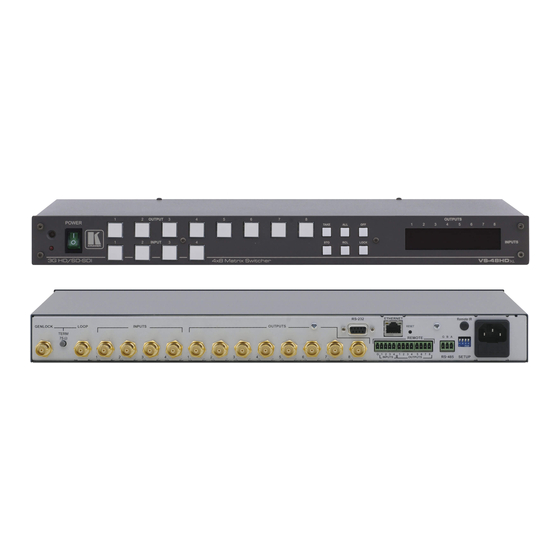
Page 8: Figure 1: Vs-48Hdxl 3G Hd/Sd Sdi 4X8 Matrix Switcher
Vertrieb von CAMBOARD Electronics Your VS-48HDxl 3G HD/SD SDI 4x8 Matrix Switcher Figure 1: VS-48HDxl 3G HD/SD SDI 4x8 Matrix Switcher www.camboard.de Tel. 07131 911201 ce-info@camboard.de Fax 07131 911203... -
Page 9: Table 1: Front Panel Vs-48Hdxl 3G Hd/Sd Sdi 4X8 Matrix Switcher
Vertrieb von CAMBOARD Electronics Your VS-48HDxl 3G HD/SD SDI 4x8 Matrix Switcher Table 1: Front Panel VS-48HDxl 3G HD/SD SDI 4x8 Matrix Switcher Feature Function IR Receiver The red LED is illuminated when receiving signals from the Infrared remote control transmitter... -
Page 10: Table 2: Rear Panel Vs-48Hdxl 3G Hd/Sd Sdi 4X8 Matrix Switcher
Vertrieb von CAMBOARD Electronics Your VS-48HDxl 3G HD/SD SDI 4x8 Matrix Switcher Table 2: Rear Panel VS-48HDxl 3G HD/SD SDI 4x8 Matrix Switcher Feature Function GENLOCK BNC Connector Connect to the Genlock source TERM 75 Button Press to terminate the Genlock source (75 ) or release for looping... -
Page 11: Using The Ir Transmitter
This distance can be extended to up to 60 meters when used with three extension cables Before using the external IR receiver, be sure to arrange for your Kramer dealer to insert the internal IR connection cable with the 3.5mm connector that fits into the REMOTE IR opening on the rear panel. -
Page 12: Installing The Vs-48Hdxl In A Rack
CAMBOARD Electronics Installing the VS-48HDxl in a Rack Installing the VS-48HDxl in a Rack This section describes how to install the VS-48HDxl in a rack. Before Installing in a rack How to Rack Mount Before installing in a rack, be sure that the environment is... -
Page 13: Connecting The Vs-48Hdxl 3G Hd/Sd Sdi 4X8 Matrix Switcher
Connect the power cord 1 Switch OFF the power on each device before connecting it to your VS-48HDxl. After connecting your VS-48HDxl, switch on its power and then switch on the power on each device 2 When only one output is required, connect that output, and leave the other outputs unconnected 3 Not illustrated in Figure 2 4 Pushed in terminates the input. -
Page 14: Figure 2: Connecting The Vs-48Hdxl 3G Hd/Sd Sdi 4X8 Matrix Switcher
Vertrieb von CAMBOARD Electronics Connecting the VS-48HDxl 3G HD/SD SDI 4x8 Matrix Switcher Figure 2: Connecting the VS-48HDxl 3G HD/SD SDI 4x8 Matrix Switcher www.camboard.de Tel. 07131 911201 ce-info@camboard.de Fax 07131 911203... -
Page 15: Connecting The Vs-48Hdxl In The Dual-Link Mode
Set the machine to the dual-link mode (see section 6.2). 1 Switch OFF the power on each device before connecting it to your VS-48HDxl. After connecting your VS-48HDxl, switch on its power and then switch on the power on each device... -
Page 16: Working Mode Setting
Figure 3: Connecting the Dual-Link VS-48HDxl 3G HD/SD-SDI 4x8 Matrix Switcher 6.2 Working Mode Setting You can set the VS-48HDxl to work in the dual-link mode as follows: To switch to the dual-link mode, press and hold the OFF front panel... -
Page 17: Dipswitch Settings
6.3.1 Setting the Setup Dipswitches The setup dipswitches determine the address of each VS-48HDxl unit when several VS-48HDxl units are connected to a PC or serial controller. Set the address of the unit using the SETUP dipswitches 1, 2, 3 and 4, according to Table 3. -
Page 18: Controlling Via Rs-232 (For Example, Using A Pc)
To connect a PC to the VS-48HDxl unit, using the Null-modem adapter provided with the machine (recommended): Connect the RS-232 9-pin D-sub rear panel port on the VS-48HDxl unit to the Null-modem adapter and connect the Null-modem adapter with a... -
Page 19: Controlling Via The Rs-485 Port
VS-48HDxl units. (If using shielded twisted pair cable, the shield is usually connected to the “G” (Ground) PIN of the first unit). Set the first VS-48HDxl unit as MACHINE # 1 and the following seven VS-48HDxl units as MACHINE # 2 to MACHINE # 8, according to Table 3. -
Page 20: Switching Genlocked Video Signals
6.8.1 Connecting the ETHERNET Port directly to a PC (Crossover Cable) You can connect the Ethernet port of the VS-48HDxl to the Ethernet port on your PC, via a crossover cable with RJ-45 connectors. This type of connection is recommended for identification of the factory default... -
Page 21: Figure 7: Local Area Connection Properties Window
Vertrieb von CAMBOARD Electronics Connecting the VS-48HDxl 3G HD/SD SDI 4x8 Matrix Switcher Right-click Local Area Connection Properties. Select Properties. The Local Area Connection Properties window appears. Select the Internet Protocol (TCP/IP) and click the Properties Button (see Figure 7). -
Page 22: Connecting The Ethernet Port Via A Network Hub (Straight-Through Cable)
Vertrieb von CAMBOARD Electronics Connecting the VS-48HDxl 3G HD/SD SDI 4x8 Matrix Switcher 6.8.2 Connecting the ETHERNET Port via a Network Hub (Straight- Through Cable) You can connect the Ethernet port of the VS-44HDxl to the Ethernet port on a network hub or network router, via a straight-through cable with RJ-45 connectors. -
Page 23: Operating The Vs-48Hdxl
Vertrieb von CAMBOARD Electronics Operating the VS-48HDxl Operating the VS-48HDxl You can operate your VS-48HDxl using the: Front panel buttons RS-232/RS-485 serial commands transmitted by a PC, touch screen system, or other serial controller Kramer RC-IR2 Infrared Remote Control Transmitter... -
Page 24: Switch Out-In Combinations In The Dual-Link Mode
Execution is delayed until the user confirms the action Note that after ten seconds the VS-48HDxl will go to standby mode and the buttons and the 7-segment display will illuminate less brightly. 1 For details of how to route an input to an output using the REMOTE connector, see section 6.9 2 For immediate switching www.camboard.de... -
Page 25: Toggling Between The At Once And Confirm Modes
Vertrieb von CAMBOARD Electronics Operating the VS-48HDxl 7.2.1 Toggling between the AT ONCE and CONFIRM Modes To toggle between the AT ONCE and CONFIRM modes, do the following: Press the dim TAKE button to toggle from the AT ONCE mode (in which the TAKE button is dim) to the CONFIRM mode (in which the TAKE button illuminates). -
Page 26: Recalling An Input/Output Configuration
1 The setup configuration is shown flashing in the 7-segment display, but it is not implemented at this stage 2 Nevertheless, even though the front panel is locked you can still operate via RS-232 or RS-485, as well as via the Kramer IR Remote Control Transmitter www.camboard.de... -
Page 27: Technical Specifications
External remote IR receiver cable Table of Hex Codes for Serial Communication Table 5 lists the Hex values for a single machine (MACHINE # 1): Table 5: VS-48HDxl Hex Codes for Switching via RS-232/RS-485 OUT 1 OUT 2 OUT 3... -
Page 28: Kramer Protocol 2000
CAMBOARD Electronics Kramer Protocol 2000 10 Kramer Protocol 2000 The VS-48HDxl is compatible with Kramer’ s Protocol 2000 (version 0.50) (below). This RS-232/RS-485 communication protocol uses four bytes of information as defined below. For RS-232, a null-modem connection between the machine and controller is used. The default data rate is 9600 baud, with no parity, 8 data bits and 1 stop bit. -
Page 29: Table 7: Instruction Codes For Protocol 2000
(HEX codes): 81 (i.e. 128dec+ 22dec for 2nd byte, and 128dec+ 16dec for 3rd byte). www.camboard.de Tel. 07131 911201 ce-info@camboard.de KRAMER: SIMPLE CREATIVE TECHNOLOGY Fax 07131 911203... - Page 30 Vertrieb von CAMBOARD Electronics Kramer Protocol 2000 If the request for identification is sent with the INPUT set as 3 or 4, the appropriate machine will send its software version number. Again, the reply would be the decimal value of the INPUT and OUTPUT - the INPUT representing the number in front of the decimal point, and the OUTPUT representing the number after it.
- Page 31 EXCLUSION OF DAMAGES The liability of Kramer for any effective products is limited to the repair or replacement of the product at our option. Kramer shall not be liable for: 1. Damage to other property caused by defects in this product, damages based upon inconvenience, loss of use of the product, loss of time, commercial loss;...
- Page 32 Vertrieb von CAMBOARD Electronics For the latest information on our products and a list of Kramer distributors, visit our Web site: www.kramerelectronics.com, where updates to this user manual may be found. We welcome your questions, comments and feedback. Safety Warning: Disconnect the unit from the power supply before opening/servicing.
Need help?
Do you have a question about the VS-48HDxl and is the answer not in the manual?
Questions and answers