Table of Contents
Advertisement
Quick Links
Advertisement
Table of Contents

Related Manuals for Kramer VS-44HD


Summary of Contents for Kramer VS-44HD
- Page 1 Kramer Electronics, Ltd. USER MANUAL Model: VS-44HD 4x4 SD/HD-SDI Matrix Switcher...
-
Page 2: Table Of Contents
Your VS-44HD 4x4 SD/HD-SDI Matrix Switcher Installing on a Rack Connecting Your VS-44HD Connecting Your VS-44HD 4x4 SD/HD-SDI Matrix Switcher Connecting the VS-44HD as a Dual-Link 2x2 SD/HD-SDI Matrix Switcher 9 Setting the VS-44HD to work in the Dual-Link Mode Dipswitch Settings 6.4.1... - Page 3 Figure 1: VS-44HD 4x4 SD/HD-SDI Matrix Switcher Figure 2: Connecting the VS-44HD 4x4 SD/HD-SDI Matrix Switcher Figure 3: Connecting the VS-44HD as a Dual-Link 2x2 SD/HD-SDI Matrix Switcher Figure 4: VS-44HD SETUP Dipswitches Figure 5: Connecting a PC without using a Null-modem Adapter...
-
Page 4: Introduction
GROUP 7: Scan Converters and Scalers; GROUP 8: Cables and Connectors; GROUP 9: Room Connectivity; GROUP 10: Accessories and Rack Adapters; GROUP 11: Sierra Products 2 Download up-to-date Kramer user manuals from the Internet at this URL: http://www.kramerelectronics.com 3 The complete list of Kramer cables is on our Web site at http://www.kramerelectronics.com... - Page 5 Getting Started KRAMER: SIMPLE CREATIVE TECHNOLOGY...
-
Page 6: Overview
The storing and recalling of setups, a Take button for the execution of multiple switches all at once, and a front panel lock The VS-44HD is housed in a 19" 1U rack mountable enclosure and is fed from a 100-240 VAC universal switching power supply. Control is via the... -
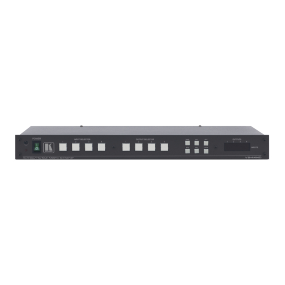
Page 7: Figure 1: Vs-44Hd 4X4 Sd/Hd-Sdi Matrix Switcher
Your VS-44HD 4x4 SD/HD-SDI Matrix Switcher Figure 1: VS-44HD 4x4 SD/HD-SDI Matrix Switcher KRAMER: SIMPLE CREATIVE TECHNOLOGY... -
Page 8: Table 1: Front Panel Vs-44Hd 4X4 Sd/Hd-Sdi Matrix Switcher
Your VS-44HD 4x4 SD/HD-SDI Matrix Switcher Table 1: Front Panel VS-44HD 4x4 SD/HD-SDI Matrix Switcher Feature Function IR Receiver The red LED illuminates when receiving signals from the infrared remote control transmitter POWER Switch Illuminated switch for turning the unit ON or OFF INPUT SELECTOR Select the input to switch to the output (from 1 to 4). -
Page 9: Installing On A Rack
5. The machine is earthed (grounded) in a reliable way power and is connected only to an electricity socket with If you are using a Kramer rack grounding. Pay particular attention to situations where adapter kit (for a machine that is not electricity is supplied indirectly (when the power cord 19"), see the Rack Adapters user... -
Page 10: Connecting Your Vs-44Hd
, connect a remote contact closure switch (refer to section 6.10) 7. Connect the power cord 1 Switch OFF the power on each device before connecting it to your VS-44HD. After connecting your VS-44HD, switch on its power and then switch on the power on each device... -
Page 11: Figure 2: Connecting The Vs-44Hd 4X4 Sd/Hd-Sdi Matrix Switcher
Connecting Your VS-44HD Figure 2: Connecting the VS-44HD 4x4 SD/HD-SDI Matrix Switcher KRAMER: SIMPLE CREATIVE TECHNOLOGY... -
Page 12: Connecting The Vs-44Hd As A Dual-Link 2X2 Sd/Hd-Sdi Matrix Switcher
4. Set the machine to the dual-link mode, see section 6.3. 1 Switch OFF the power on each device before connecting it to your VS-44HD. After connecting your VS-44HD, switch on its power and then switch on the power on each device... -
Page 13: Setting The Vs-44Hd To Work In The Dual-Link Mode
Figure 3: Connecting the VS-44HD as a Dual-Link 2x2 SD/HD-SDI Matrix Switcher 6.3 Setting the VS-44HD to work in the Dual-Link Mode You can set the VS-44HD to work in the dual-link mode as follows: To switch to the dual-link mode, press and hold the OFF front panel button for... -
Page 14: Dipswitch Settings
The Machine # determines the position of a VS-44HD unit, specifying which VS-44HD unit is being controlled when several VS-44HD units connect to a PC or serial controller. Set the Machine # on a VS-44HD unit via SETUP DIPS 1, 2, 3 and 4, according to Table 3. -
Page 15: Controlling Via Rs-232 (For Example, Using A Pc)
To connect a PC to the VS-44HD unit, using the Null-modem adapter provided with the machine (recommended): Connect the RS-232 DB9 rear panel port on the VS-44HD unit to the Null-modem adapter and connect the Null-modem adapter with a 9 wire... -
Page 16: Controlling Via The Rs-485 Port
VS-44HD units. (If using shielded twisted pair cable, the shield is usually connected to the “G” (Ground) PIN of the first unit). 2. Set the first VS-44HD unit as MACHINE # 1 and the following seven VS-44HD units as MACHINE # 2 to MACHINE # 8, according to Table... -
Page 17: Factory Reset
6.9.1 Connecting the ETHERNET Port directly to a PC (Crossover Cable) You can connect the Ethernet port of the VS-44HD to the Ethernet port on your PC, via a crossover cable with RJ-45 connectors. This type of connection is recommended for identification of the factory default... -
Page 18: Figure 7: Local Area Connection Properties Window
Connecting Your VS-44HD 2. Select Properties. 3. Right-click Local Area Connection Properties. 4. Select Properties. The Local Area Connection Properties window appears. 5. Select the Internet Protocol (TCP/IP) and click the Properties Button (see Figure 7). Figure 7: Local Area Connection Properties Window 6. -
Page 19: Connecting The Ethernet Port Via A Network Hub (Straight-Through Cable)
6.9.2 Connecting the ETHERNET Port via a Network Hub (Straight- Through Cable) You can connect the Ethernet port of the VS-44HD to the Ethernet port on a network hub or network router, via a straight-through cable with RJ-45 connectors. 6.9.3 Configuring the Ethernet Port After connecting the Ethernet port, you have to install and configure it. -
Page 20: Operating The Vs-44Hd
Operating the VS-44HD Operating the VS-44HD You can operate your VS-44HD via: The front panel buttons RS-232/RS-485 serial commands transmitted by a PC, touch screen system, or other serial controller The Kramer infrared remote control transmitter The ETHERNET 7.1 Switching OUT-IN Combinations... -
Page 21: Confirming Settings
Every action requires user confirmation, protecting against erroneous switching Execution is delayed until the user confirms the action Note that after ten seconds the VS-44HD will go to standby mode and the buttons and the 7-segment display will illuminate less brightly 7.3.1... -
Page 22: Storing/Recalling Input/Output Configurations
Operating the VS-44HD 2. Press the TAKE button to confirm the action. The 7-segment Display no longer blinks. The TAKE button illuminates. To confirm several actions (in CONFIRM mode), do the following: 1. Press each OUT-IN combination in sequence. The 7-segment Display blinks. -
Page 23: Locking The Front Panel
Technical Specifications 7.5 Locking the Front Panel To prevent changing the settings accidentally or tampering with the unit via the front panel buttons, lock your VS-44HD. Unlocking releases the protection mechanism. To lock the VS-44HD: Press the LOCK button for three seconds, until the LOCK button is illuminated. -
Page 24: Kramer Protocol 2000
Kramer Protocol 2000 10 Kramer Protocol 2000 The VS-44HD is compatible with Kramer’ s Protocol 2000 (version 0.46) (below). This RS-232/RS-485 communication protocol uses four bytes of information as defined below. For RS-232, a null-modem connection between the machine and controller is used. The default data rate is 9600 baud, with no parity, 8 data bits and 1 stop bit. -
Page 25: Table 7: Instruction Codes For Protocol 2000
MACHINE ADDRESS 1 - for audio REQUEST WHETHER SETUP # 0 - for checking if setup is defined SETUP IS DEFINED / 1 - for checking if input is valid VALID INPUT IS Input # DETECTED KRAMER: SIMPLE CREATIVE TECHNOLOGY... - Page 26 Kramer Protocol 2000 INSTRUCTION DEFINITION FOR SPECIFIC INSTRUCTION NOTE DESCRIPTION INPUT OUTPUT ERROR / BUSY For invalid / valid input (i.e. OUTPUT 0 - error 9, 25 byte = 4 or OUTPUT byte = 5), 1 - invalid instruction this byte is set as the input #...
- Page 27 OUTPUT byte set as 7, the VIS source is the output selected using the OUTPUT byte. Note also, that on some machines the sync source is not software selectable, but is selected using switches, jumpers, etc! KRAMER: SIMPLE CREATIVE TECHNOLOGY...
- Page 28 Kramer Protocol 2000 NOTE 6 – If INPUT is set to 127 for these instructions, then, if the function is defined on this machine, it replies with OUTPUT=1. If the function is not defined, then the machine replies with OUTPUT=0, or with an error (invalid instruction code).
- Page 29 (in real-time). For example, if input 3 is detected as invalid, the unit will send the HEX codes If input 7 is detected as valid, then the unit will send HEX codes KRAMER: SIMPLE CREATIVE TECHNOLOGY...
- Page 30 EXCLUSION OF DAMAGES The liability of Kramer for any effective products is limited to the repair or replacement of the product at our option. Kramer shall not be liable for: 1. Damage to other property caused by defects in this product, damages based upon inconvenience, loss of use of the product, loss of time, commercial loss;...
- Page 32 For the latest information on our products and a list of Kramer distributors, visit our Web site: www.kramerelectronics.com, where updates to this user manual may be found. We welcome your questions, comments and feedback. Safety Warning: Disconnect the unit from the power supply before opening/servicing.
Need help?
Do you have a question about the VS-44HD and is the answer not in the manual?
Questions and answers