
Related Manuals for IBM BNT RackSwitch G8124R


Summary of Contents for IBM BNT RackSwitch G8124R
- Page 1 IBM BNT RackSwitch G8124R, IBM BNT RackSwitch G8124F, IBM BNT RackSwitch G8124ER, IBM BNT RackSwitch G8124EF, and IBM BNT RackSwitch G8124DC Type 0446 and 7309 Installation Guide...
- Page 3 IBM BNT RackSwitch G8124R, IBM BNT RackSwitch G8124F, IBM BNT RackSwitch G8124ER, IBM BNT RackSwitch G8124EF, and IBM BNT RackSwitch G8124DC Type 0446 and 7309 Installation Guide...
- Page 4 Appendix B on page 47, the Safety Information and Environmental Notices and User Guide documents on the IBM Documentation CD, and the Warranty Information document that comes with the product. First Edition (May 2011) © Copyright IBM Corporation 2011.
-
Page 5: Safety
Safety Safety... - Page 6 Important Each caution and danger statement in this document is labeled with a number. This number is used to cross reference an English-language caution or danger statement with translated versions of the caution or danger statement in the Systems Safety Notices document. For example, if a caution statement is labeled “D005,”...
- Page 7 Safety...
- Page 8 viii BNT RackSwitch G8124 Installation Guide...
- Page 9 Safety...
- Page 10 Wire size 16 AWG (IBM part number 90Y3538 DC power cable from PDP output to server input) 1.31 mm2 Wiring terminal screw torque -- inch-pounds (IBM part number 90Y3538 provided with connector, both ends) -- newton-meters BNT RackSwitch G8124 Installation Guide...
- Page 11 Safety...
- Page 12 BNT RackSwitch G8124 Installation Guide...
-
Page 13: Table Of Contents
Contents Safety Chapter 1: Introduction The IBM Documentation CD Related Documentation Notices and Statements in this Document RackSwitch G8124 Features Performance Management Features Software Features Switch Components Hardware Options Switch Unit Switch Ports LEDs Technical Specifications Physical Characteristics Environmental Specifications... - Page 14 Appendix A: Getting Help and Technical Assistance Before You Call Using the Documentation Getting Help and Information from the World Wide Web Software Service and Support Hardware Service and Support IBM Taiwan Product Service Appendix B: Notices Trademarks Telecommunication Regulatory Statement Important Notes Particulate Contamination...
-
Page 15: Chapter 1: Introduction
For information about configuration and management of the switch, refer to your Command Reference and the product release notes. If firmware and documentation updates are available, you can download them from the IBM website. The switch might have features that are not described in the documentation that comes... -
Page 16: The Ibm Documentation Cd
The IBM Documentation CD The IBM Documentation CD contains documentation for your switch in Portable Document Format (PDF) and includes the IBM Documentation Browser to help you find information quickly. Hardware and Software Requirements The IBM Documentation CD requires the following minimum hardware and software: Microsoft Windows NT 4.0 (with Service Pack 3 or later), Windows 2000, or Red Hat®... -
Page 17: Related Documentation
Notices and Statements in this Document The caution and danger statements in this document are also in the multilingual Safety Information document, which is on the IBM® Documentation CD. Each statement is numbered for reference to the corresponding statement in the Safety Information document. -
Page 18: Rackswitch G8124 Features
RackSwitch G8124 Features This section provides an overview of RackSwitch G8124 features. Performance 240 Gbps throughput (full duplex), non-blocking switching architecture 100% line rate at all packet sizes Deterministic port-to-port latency under 700 nanoseconds with 64B packets Management Features Clients Industry standard command-line interface (ISCLI) Browser-based Interface (BBI) BladeHarmony Manager... - Page 19 Layer 2 1024 VLANs (802.1Q), including Private VLANs Multi-link trunking, compatible with Cisco EtherChannel LACP (IEEE 802.3ad) Spanning Tree (802.1D), Multiple Spanning Tree (802.1s), Rapid Spanning Tree (802.1w), with Fast Uplink Convergence 16K forwarding database entries Layer 3 128 configurable interfaces (static or DHCP) IP forwarding IGMP Snooping v1, v2, v3 4K ARP entries...
-
Page 20: Switch Components
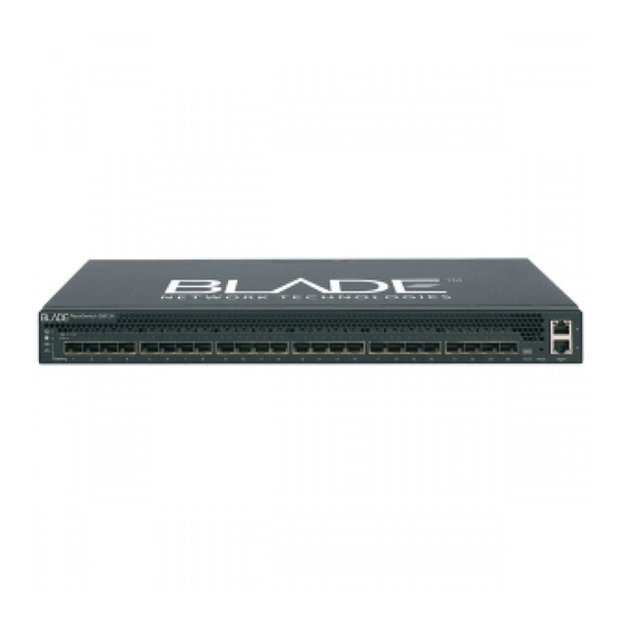
Switch unit Mounting hardware Standard rack mounting brackets and screws ™ IBM iDataPlex rack mounting brackets and screws 4-post rack mounting brackets and screws Switch Unit Each RackSwitch G8124 series switch unit is a 1U rack-mountable 10 Gigabit Ethernet switch. - Page 21 10101 Reset Reset button System status LEDs RS-232 port SFP+ slots Figure 2 IBM BNT RackSwitch G8124 Rear Panel (AC) IEC 320 IEC 320 Power connector Power connector Figure 3 IBM BNT RackSwitch G8124 Rear Panel (DC) DC Power connector...
-
Page 22: Reset Button
Reset Button The Reset button is recessed within a hole on the front panel. Use a straightened paper clip or similar object to press the Reset button. The Reset button allows technicians to reset the switch, as follows: Press Reset: The switch resets and reloads the configuration files. Press and hold Reset for five seconds: The switch resets and configures all settings to factory defaults. -
Page 23: Dc Power Supply
The Power Supply LED indicates the status of the power supplies. The LED blinks when only one power cord is connected or if one power supply fails. The LED lights steady when both power cords are connected and operating. DC Power Supply The DC Powered G8124 has two redundant 250W DC-DC power supplies, operating from 42V to 60V. - Page 24 BNT RackSwitch G8124 Installation Guide...
- Page 25 16 AWG (IBM part number 90Y3538 DC power cable from PDP output to server input) 1.31 mm2 Wiring terminal screw torque -- inch-pounds (IBM part number 90Y3538 provided with connector, both ends) -- newton-meters Each power supply can be connected to a separate DC power source to mitigate the risk of down time during a power failure.
-
Page 26: Switch Ports
SFP transceivers, optical SFP+ transceivers, or Direct Attach Cables (DAC). Transceivers are not included with the G8124 switch unit. For the available transceivers and direct attach cables (DACs) for the switch, see https://www-01.ibm.com/products/hardware/configurator/americas/bhui/launchNI.wss The RackSwitch G8124 accepts any SFP+ Direct Attach Cable that complies to the MSA specification. - Page 27 10/100/1000Base-T Ports Two 10/100/1000BaseT ports (RJ-45) are located on the front panel. These management ports support in-line management and Control Plane Stacking. The following table describes the RJ-45 connector pin assignments. Table 1 RJ-45 Port pin assignments Pin number Signal Description BI DA+ Bi-directional data pair A positive...
-
Page 28: Console Port
Console Port The RS-232 (mini-USB) serial console port is located on the front panel. An external cable is required to convert to a D9 connector. The following table describes the pinouts for the mini-USB port: Table 2 Console Port pin assignments Pin number Function Pin 1... -
Page 29: Leds
LEDs Two LED stacks provide system status and port link status. The system LEDs are described in the following table: Power supplies and AC power input status Fans status Stacking master indicator Stacking member indicator The following table describes the system LED indications: Table 4 System LEDs Status Function... - Page 30 XGE Port LEDs Figure 4 highlights the system LEDs and SFP+ port LEDs. Figure 4 System Status LEDs and Port LEDs BLADE Rackswitch G8124 Stacking Status and link LEDs for the data port slots are described in the following table. Table 5 SFP+ LEDs Status Solid Green...
-
Page 31: Technical Specifications
Technical Specifications This section provides specifications for the RackSwitch G8124. Physical Characteristics Physical characteristics of the RackSwitch G8124F/G81240R switch unit are listed in the following table. Table 7 Physical Characteristics Specification G8124F G8124R Dimensions (H x W x D) 1.73 x 17.3 x 15.0 in. 1.73 x 17.3 x 15.0 in. -
Page 32: Power Specifications
Table 8 Environmental Specifications Specification Measurement Acoustic noise less than 65dB Heat dissipation 1100 BTU/hour (maximum) Power Specifications Power specifications for the RackSwitch G8124F/G8124R switch unit are listed in Table 9 Table Table 9 AC Power Specifications Specification Measurement Number of power supplies 2 (1+1 redundant) AC-input frequency (universal) 50-60 Hz... -
Page 33: Chapter 2: Installing The Rackswitch G8124
G8124 switch unit: Standard rack mount kit Two brackets Screws to attach brackets to the switch unit Screws to attach the switch unit to the equipment rack Mini-USB serial cable Two AC or DC power cords Copyright IBM Corp. 2011 ©... -
Page 34: Environmental Requirements
Environmental Requirements This section describes the basic environmental requirements for the RackSwitch G8124. Make sure the location where you install the switch meets the following requirements: Install the switch unit in a dry, clean, well-ventilated area. Provide adequate space on all sides of the switch unit, to ensure proper air flow. Make sure that an adequate grounded power supply is within reach of the switch unit. - Page 35 Installing the RackSwitch G8124...
-
Page 36: Handling Static-Sensitive Devices
Handling Static-Sensitive Devices Attention: Static electricity can damage the switch and other electronic devices. To avoid damage, keep static-sensitive devices in their static-protective packages until you are ready to install them. To reduce the possibility of electrostatic discharge, observe the following precautions: Limit your movement. -
Page 37: Installing The Rackswitch G8124 In A Standard Equipment Rack
Installing the RackSwitch G8124 in a Standard Equipment Rack This section describes how to install the RackSwitch G8124 in a standard 19-inch equipment rack. For information about mounting the G8124 in other rack types, refer to the following sections: “Installing the RackSwitch G8124 in an iDataPlex Rack” on page 26 “Installing the RackSwitch G8124 in a 4-post Rack”... - Page 38 Use the M4 screws to attach a mounting bracket to each side of the switch. Torque the screws to approximately 10 inch-pounds (1.1 Nm). Figure 5 Attaching the Mounting Brackets BNT RackSwitch G8124 Installation Guide...
- Page 39 Slide the switch into the rack as illustrated. Figure 6 Rack-mounting the Switch Unit Use M6 screws, washers, and clip nuts to secure the switch unit to the rack. Torque the screws to approximately 30 inch-pounds (3.5 Nm). Installing the RackSwitch G8124...
-
Page 40: Installing The Rackswitch G8124 In An Idataplex Rack
Rack This section provides general information about installing the RackSwitch G8124 in an IBM iDataPlex rack. The iDataPlex mounting kit allows the switch to be mounted either vertically or horizontally. For information about mounting the G8124 in other rack types, refer to the following sections: “Installing the RackSwitch G8124 in a Standard Equipment Rack”... - Page 41 Perform the following steps to mount the RackSwitch G8124 into an iDataPlex rack. Use the M4 screws to attach front and rear mounting brackets to each side of the switch unit. Torque the screws to approximately 10 inch-pounds (1.1 Nm). Figure 7 Attaching the Mounting Brackets Installing the RackSwitch G8124...
- Page 42 M6 screws, washers, and clip nuts are used to attach the alignment plate. Torque the screws to approximately 30 inch-pounds (3.5 Nm). Figure 8 Attaching the Alignment Plate M6 screws, washers, and clip nuts are used to mount the switch unit into the rack. Torque the screws to approximately 30 inch-pounds (3.5 Nm).
-
Page 43: Installing The Rackswitch G8124 In A 4-Post Rack
4-post Rack This section provides general information about installing the RackSwitch G8124 in a 4-post rack, including the IBM e1350 - Type 1410. For information about mounting the G8124 in other rack types, refer to the following sections: “Installing the RackSwitch G8124 in a Standard Equipment Rack” on page 23 “Installing the RackSwitch G8124 in an iDataPlex Rack”... - Page 44 Perform the following steps to mount the RackSwitch G8124 into a standard 4-post rack. Use the M4 screws to attach a horizontal rail to each side of the switch. Torque the screws to approximately 10 inch-pounds (1.1 Nm). Figure 10 Attaching the Horizontal Rail M6 screws, washers, and clip nuts are used to connect the horizontal rail to the front posts in the rack.
- Page 45 The rear mounting brackets are secured to the rack with M6 screws, washers, and clip nuts. Torque the screws to approximately 30 inch-pounds (3.5 Nm). Figure 12 Attaching Rear Mounting Brackets The front mounting brackets and the rear mounting brackets are secured with M3 screws. Torque the screws to approximately 4 inch-pounds (0.5 Nm).
-
Page 46: Initializing The Rackswitch G8124
Initializing the RackSwitch G8124 When you plug in the G8124 power cord, the switch initializes automatically. The following LEDs indicate the overall system status: Power Supply = Solid Green if both power cords are connected, blinking green if only one power cord is connected Fan = Solid Green if all fans are running, blinking green if there is a fan failure BNT RackSwitch G8124 Installation Guide... -
Page 47: Default Configuration
Use the mini-USB console cable to connect the RS-232 serial port on the switch unit’s front panel to a terminal or a PC running a terminal emulation program. You can access the command-line interface to perform initial configuration tasks. The console port’s terminal-emulation requirements are as follows: Default baud rate = 9,600 bps Character size = 8 characters Parity = none... -
Page 48: Configuring An Ip Interface
Configuring an IP Interface To manage the switch using Telnet, SNMP, or a Web browser, you must configure an IP interface. Configure the following IP parameters: IP address Subnet mask Gateway address Log on to the switch. Enter Global Configuration mode. RS G8124>... -
Page 49: Using The Boot Management Menu
Using the Boot Management Menu The Boot Management menu allows you to switch the software image, reset the switch to factory defaults, or to recover from a failed software download. You can interrupt the boot process and enter the Boot Management menu from the serial console port. -
Page 50: Installing An Sfp Or Sfp+ Transceiver
Installing an SFP or SFP+ Transceiver The RackSwitch G8124 supports the following Small Form Factor Pluggable (SFP+) transceivers: SFP+ 10GBase-SR Short Range Transceiver SFP+ 10GBase-LR Long Range Optical Fiber Transceiver SFP 1000BASE-T Copper Transceiver Transceiver SFP 1000BASE-T-SX Short Range Optical SFP+ Optical Transceiver The G8124 only accepts approved SFP+ transceivers. -
Page 51: Sfp Copper Transceiver
Remove the safety cap and pull the locking lever into the down (unlocked) position. Insert the transceiver into the port until it clicks into place. Use minimal pressure when you insert the transceiver into the slot. Do not use excessive force when you insert the transceiver;... -
Page 52: Troubleshooting
Troubleshooting This section contains basic troubleshooting information. Use it to help resolve problems that may occur during installation and operation of your switch. If you have problems accessing the switch or working with switch software, refer to your RackSwitch G8124 Application Guide or Command Reference. -
Page 53: Switch Does Not Initialize (Boot)
Switch Does Not Initialize (Boot) Symptom: All the switch LEDs stay on, and the command prompt does not appear on the console. Solution: The operating system may have been damaged. Use the console port to perform a serial upgrade of the switch software. Refer to your Command Reference. Installing the RackSwitch G8124... - Page 54 BNT RackSwitch G8124 Installation Guide...
-
Page 55: Chapter 3: Replaceable Parts
Replaceable Parts The replaceable switch parts are Tier 1 customer replaceable units (CRUs). Replacement of Tier 1 CRUs is your responsibility. If IBM installs a Tier 1 CRU at your request, you will be charged for the installation. For information about the terms of the warranty, see the Warranty Information document that comes with the switch. - Page 56 Table 15 IBM BNT RackSwitch G8124R, Type 0446; RackSwitch G8124F, RackSwitch G8124ER, RackSwitch G8124EF, and RackSwitch G8124DC, Type 7309 Replaceable Parts Description Model Option part Tier 1 CRU number part number Cable, 3 m IBM passive BD5, BR6, BF7, BF9...
-
Page 57: Appendix A: Getting Help And Technical Assistance
If you need help, service, or technical assistance or just want more information about IBM products, you will find a wide variety of sources available from IBM to assist you. This section contains information about where to go for additional information about IBM and IBM products, what to do if you experience a problem with your system, and whom to call for service, if it is necessary. -
Page 58: Using The Documentation
IBM maintains pages on the World Wide Web where you can get the latest technical information and download device drivers and updates. To access these pages, go to http://www.ibm.com/supportportal/... -
Page 59: Ibm Taiwan Product Service
In the U.S. and Canada, hardware service and support is available 24 hours a day, 7 days a week. In the U.K., these services are available Monday through Friday, from 9 a.m. to 6 p.m. IBM Taiwan Product Service IBM Taiwan product service contact information: IBM Taiwan Corporation 3F, No 7, Song Ren Rd. - Page 60 BNT RackSwitch G8124 Installation Guide...
-
Page 61: Appendix B: Notices
Consult your local IBM representative for information on the products and services currently available in your area. Any reference to an IBM product, program, or service is not intended to state or imply that only that IBM product, program, or service may be used. Any functionally equivalent product, program, or service that does not infringe any IBM intellectual property right may be used instead. -
Page 62: Trademarks
The materials at those websites are not part of the materials for this IBM product, and use of those websites is at your own risk. IBM may use or distribute any of the information you supply in any way it believes appropriate without incurring any obligation to you. -
Page 63: Important Notes
If IBM determines that the levels of particulates or gases in your environment have caused damage to the device, IBM may condition provision of repair or... -
Page 64: Documentation Format
If you experience difficulties when you use the PDF files and want to request a web-based format or accessible PDF document for a publication, direct your mail to the following address: Information Development IBM Corporation 205/A015 3039 E. Cornwallis Road P.O. Box 12195 Research Triangle Park, North Carolina 27709-2195 U.S.A. -
Page 65: Electronic Emission Notices
In the request, be sure to include the publication part number and title. When you send information to IBM, you grant IBM a nonexclusive right to use or distribute the information in any way it believes appropriate without incurring any obligation to you. -
Page 66: European Union Emc Directive Conformance Statement
EU-Mitgliedsstaaten und hält die Grenzwerte der EN 55022 Klasse A ein. Um dieses sicherzustellen, sind die Geräte wie in den Handbüchern beschrieben zu installieren und zu betreiben. Des Weiteren dürfen auch nur von der IBM empfohlene Kabel angeschlossen werden. IBM übernimmt keine Verantwortung für die Einhaltung der Schutzanforderungen, wenn das Produkt ohne Zustimmung der IBM verändert bzw. -
Page 67: Japan Vcci Class A Statement
914-499-1900 Der verantwortliche Ansprechpartner des Herstellers in der EU ist: IBM Deutschland Technical Regulations, Department M456 IBM-Allee 1, 71137 Ehningen, Germany Telephone: +49 7032 15-2937 E-mail: tjahn@de.ibm.com Generelle Informationen: Das Gerät erfüllt die Schutzanforderungen nach EN 55024 und EN 55022 Klasse A. - Page 68 Japan Electronics and Information Technology Industries Association (JEITA) Statement Japanese Electronics and Information Technology Industries Association (JEITA) Confirmed Harmonics Guideline (products less than or equal to 20 A per phase) Korea Communications Commission (KCC) Statement Please note that this equipment has obtained EMC registration for commercial use. In the event that it has been mistakenly sold or purchased, please exchange it for equipment certified for home use.
- Page 69 Russia Electromagnetic Interference (EMI) Class A Statement People's Republic of China Class A Electronic Emission Statement Taiwan Class A Compliance Statement Notices...
- Page 70 ® Part Number: 60Y1448 Printed in USA BNT RackSwitch G8124 Installation Guide...
Need help?
Do you have a question about the BNT RackSwitch G8124R and is the answer not in the manual?
Questions and answers