Table of Contents
Advertisement
Quick Links
Advertisement
Table of Contents

Related Manuals for IBM G8124


Summary of Contents for IBM G8124
- Page 1 IBM System Networking RackSwitch G8124 and G8124-E Installation Guide...
- Page 3 IBM System Networking RackSwitch G8124 and G8124-E Installation Guide...
- Page 4 Note: Before using this information and the product it supports, read the Warranty Information document, the general information in Appendix B, “Notices,” on page 61, and the Important Notices document that comes with the product. Read the IBM System Safety Notices and the License Agreement for Machine Code (LAMC) document on the IBM Documentation CD.
- Page 5 Prima di installare questo prodotto, leggere le Informazioni sulla Sicurezza. Les sikkerhetsinformasjonen (Safety Information) før du installerer dette produktet. Antes de instalar este produto, leia as Informações sobre Segurança. Antes de instalar este producto, lea la información de seguridad. © Copyright IBM Corp. 2013...
- Page 6 DANGER Hazardous voltage, current, or energy levels are present inside any component that has this label attached. Do not open any cover or barrier that contains this label. (L001) IBM System Networking RackSwitch G8124 and G8124-E: Installation Guide...
- Page 7 DANGER Rack-mounted devices are not to be used as shelves or work spaces. (L002) Safety...
- Page 8 It is the responsibility of the customer to ensure that the outlet is correctly wired and grounded to prevent an electrical shock. (D004) IBM System Networking RackSwitch G8124 and G8124-E: Installation Guide...
- Page 9 Safety...
- Page 10 Electrical voltage and current from power, telephone, and communication cables are hazardous. To avoid a shock hazard: v Connect power to this unit only with the IBM provided power cord. Do not use the IBM provided power cord for any other product.
- Page 11 CAUTION: Ensure the building power circuit breakers are turned off BEFORE you connect the power cord or cords to the building power. (C023) CAUTION: This product might contain one or more of the following devices: CD-ROM drive, DVD-ROM drive, DVD-RAM drive, or laser module, which are Class 1 laser products.
- Page 12 It is the responsibility of the customer to ensure that the outlet is correctly wired and grounded to prevent an electrical shock. (R001 part 1 of 2) IBM System Networking RackSwitch G8124 and G8124-E: Installation Guide...
- Page 13 CAUTION: v Do not install a unit in a rack where the internal rack ambient temperatures will exceed the manufacturer’s recommended ambient temperature for all your rack-mounted devices. v Do not install a unit in a rack where the air flow is compromised. Ensure that air flow is not blocked or reduced on any side, front, or back of a unit used for air flow through the unit.
- Page 14 IBM System Networking RackSwitch G8124 and G8124-E: Installation Guide...
-
Page 15: Table Of Contents
Chapter 1. Introduction ..... . 1 The IBM Documentation CD ....1 Hardware and software requirements . - Page 16 ....57 How to send Dynamic System Analysis data to IBM ... 58 Using the documentation .
-
Page 17: Chapter 1. Introduction
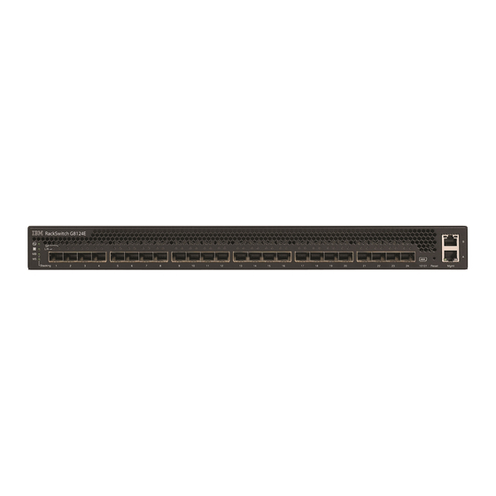
The RackSwitch G8124-E is a performance-enhanced switch with a faster management processor for improved aggregation layer functionality. Both the RackSwitch G8124 and G8124-E have identical Layer 2 and Layer 3 data plane performance characteristics. The RackSwitch G8124 contains twenty-four 10 Gb SFP+ ports and two RJ-45 management ports. -
Page 18: Related Documentation
Notices and statements in this document The caution and danger statements in this document are also in the multilingual Safety Information document, which is on the IBM Documentation CD. Each statement is numbered for reference to the corresponding statement in the Safety Information document. -
Page 19: Major Components
– Layer 2 failover – VRRP Major components This section describes the RackSwitch hardware components. Hardware options The following list provides an overview of G8124 hardware: v Switch unit v Mounting hardware – Standard rack mounting brackets and screws ®... -
Page 20: Switch Unit
(for Power and System x racks that must be purchased separately) Switch unit The RackSwitch G8124 switch unit is a 1U rack-mountable 10 Gigabit Ethernet switch. You can mount it in either the horizontal or vertical direction. The RackSwitch G8124 and G8124-E allow for flexible mounting, as follows:... - Page 21 IEC 320 IEC 320 Power connector Power connector Figure 3. IBM System Networking RackSwitch G8124 rear panel (AC) DC Power connector DC Power connector Figure 4. IBM System Networking RackSwitch G8124 rear panel (DC) Reset button The Reset button is recessed within a hole on the right-side of the front panel. Use a straightened paper clip or similar object to press the Reset button.
-
Page 22: Dc Power Supply
There is no power switch on the G8124; the switch unit powers up when power is supplied through the power cords. The Power Supply LED indicates the status of the power supplies. The LED flashes when only one power cord is connected, and is steady when both power cords are connected and operating. - Page 23 The Power Supply LED indicates the status of the power supplies. The LED flashes when only one DC power source is connected, and is steady when both DC power sources are connected. Note: DC power is not available for the RackSwitch G8124-E. Chapter 1. Introduction...
-
Page 24: Switch Ports
DACs. Transceivers must be purchased separately. For the available transceivers and DACs for the switch, see https://www- 01.ibm.com/products/hardware/configurator/americas/bhui/launchNI.wss. The RackSwitch G8124 accepts any SFP+ DAC that complies to the MSA specification. 10/100/1000 Base-T ports Two 10/100/1000Base-T ports (RJ-45) are located on the front panel. These... -
Page 25: Switch Leds
Table 3. RJ-45 connector pin assignments (continued) Pin number Signal Description BI DB- Bi-directional data pair B negative BI DC+ Bi-directional data pair C negative BI DC- Bi-directional data pair C negative BI DD+ Bi-directional data pair D negative BI DD- Bi-directional data pair D negative Console port... - Page 26 No Link RJ-45 LEDs The RJ-45 LEDs are shown in the following illustration. RJ-45 port LEDs Link LED Activity LED Status LEDs for the RJ-45 ports are described in the following table. IBM System Networking RackSwitch G8124 and G8124-E: Installation Guide...
-
Page 27: Technical Specifications
Not applicable Activity No activity Technical specifications The RackSwitch technical specifications are described in the following sections. Physical characteristics The physical characteristics of the RackSwitch G8124 are listed in the following table. Table 10. Physical characteristics Specification Front-to-rear airflow Rear-to-front airflow Dimensions (H x W x D) 4.4 x 43.9 x 38.1 cm. - Page 28 Table 13. DC power specifications Specification Measurement Number of power supplies 2 (1+1 redundant) Input Voltage 42 to 60 VDC 48 VDC (nominal) Input Current (maximum) 5.2 A Power supply output power 250 W IBM System Networking RackSwitch G8124 and G8124-E: Installation Guide...
-
Page 29: Chapter 2. Installing The Rackswitch And Options
“Installing the RackSwitch in a standard equipment rack” on page 18 v “Installing the RackSwitch in an IBM iDataPlex rack” on page 21 v “Installing the RackSwitch in an IBM System x or Power rack” on page 24 v “Installing the 1U air duct option” on page 28 v “Installing an SFP or SFP+ transceiver”... - Page 30 Record this information below and print this page and keep it in a safe place for possible future reference and customer support. You will need this information when you register the switch with IBM. You can register the switch at http://www.ibm.com/support/mysupport/.
-
Page 31: Required Tools
_____________________________________________ components _____________________________________________ _____________________________________________ Required tools You need the following tools or equipment to install the RackSwitch G8124: v Standard flat-blade screwdriver v #2 Phillips screwdriver v Electrostatic discharge wrist strap Package contents The basic package contains the following items:... -
Page 32: Preventing Electric Shock
This product does not contain any user-serviceable parts. Do not remove the cover of this device. The G8124 AC power model is designed to work with single-phase power systems that have a grounded neutral conductor. To reduce the risk of electric shock, always plug the power cord into a grounded power outlet. - Page 33 DANGER When working on or around the system, observe the following precautions: Electrical voltage and current from power, telephone, and communication cables are hazardous. To avoid a shock hazard: v Connect power to this unit only with the provided power cord. Do not use the provided power cord for any other product.
-
Page 34: Handling Static-Sensitive Devices
“Installing the RackSwitch in an IBM iDataPlex rack” on page 21 v “Installing the RackSwitch in an IBM System x or Power rack” on page 24 The following parts come in the standard mounting kit. Table 14. 2-post rack mounting kit parts... - Page 35 Attention: The rack-mounting frame may not be able to support the weight of the networking switch with only the front post mounting brackets (2-post application). If the switch has an undesirable amount of sag, it is recommended to use a 4-post mounting kit.
- Page 36 Ensure the VPD is updated to avoid losing the licensed electronic entitlement data of the RackSwitch. For more information, see “Configuring Vital Product Data after a switch replacement” on page 41 IBM System Networking RackSwitch G8124 and G8124-E: Installation Guide...
-
Page 37: Installing The Rackswitch In An Ibm Idataplex Rack
“Installing the RackSwitch in a standard equipment rack” on page 18 v “Installing the RackSwitch in an IBM System x or Power rack” on page 24 The iDataPlex rack mount kit must be purchased separately. The following table lists the parts included in the iDataPlex mounting kit. - Page 38 4. Slide the RackSwitch into the rack. 5. Use the M6 washers, screws, and clip nuts to attach the alignment plate. Torque the screws to approximately 5.7 Nm +/- 0.1 Nm (50 inch-pounds). IBM System Networking RackSwitch G8124 and G8124-E: Installation Guide...
- Page 39 6. Connect all cables. 7. Initialize the switch, see Chapter 4, “Initializing the RackSwitch,” on page 43. Attention: If this is a switch replacement, make sure the VPD is updated to avoid losing the licensed electronic entitlement data of the RackSwitch. For more information, see “Configuring Vital Product Data after a switch replacement”...
-
Page 40: Installing The Rackswitch In An Ibm System X Or Power Rack
Installing the RackSwitch in an IBM System x or Power rack This section describes how to install the RackSwitch in an IBM System Networking adjustable 19” 4-post rail rack (for Power and System x racks). For information about mounting the RackSwitch in other rack types, see the following sections: v “Installing the RackSwitch in a standard equipment rack”... - Page 41 To install the RackSwitch in an IBM System Networking adjustable 19” 4-post rack (for Power and System x racks), complete the following steps: 1. Locate and record the product switch information to configure and register your product and set aside. See “Before installing the RackSwitch” on page 13.
- Page 42 4. Slide the rear mounting brackets into the slots available on the front mounting brackets. SEE STEP 5 IBM System Networking RackSwitch G8124 and G8124-E: Installation Guide...
- Page 43 5. Use the M6 washers, screws, and clip nuts to attach the filler plate to the rear mounting brackets. Torque the screws to approximately 5.7 Nm +/- 0.1 Nm (50 inch-pounds). 6. Use the M3.5 screws to secure the rear brackets to the front brackets. Torque the screws to approximately 2.0 Nm +/- 0.1 Nm (17.7 inch-pounds).
-
Page 44: Installing The 1U Air Duct Option
The rack-mounting frame may not be able to support the weight of the networking switch with only the front post mounting brackets (2-post application). If the switch has an undesirable amount of sag, it is recommended to use a 4-post mounting kit. IBM System Networking RackSwitch G8124 and G8124-E: Installation Guide... - Page 45 Attention: For earthquake stability, mount the switch in a 4-post rack. DANGER Rack-mounted devices are not to be used as shelves or work spaces. (L002) To install the 1U air duct option in a 19" rack, complete the following steps. 1.
- Page 46 Torque the screws to approximately 2.0 Nm +/- 0.1 Nm (17.7 inch-pounds). 6. Gently slide the air duct unit side flanges into the card guides until the unit is seated firmly. Make sure that the foam strip is oriented on top. IBM System Networking RackSwitch G8124 and G8124-E: Installation Guide...
- Page 47 Foam Card guides thumbscrews Side flanges 7. Use the two M4 thumbscrews to secure the air duct unit to the air duct brackets. For information about removing the air duct, see “Removing the 1U air duct option” on page 40. Chapter 2.
-
Page 48: Installing An Sfp Or Sfp+ Transceiver
The SFP copper transceiver provides an RJ-45 connector that accepts a standard 10/100/1000BASE-T (category 5) cable. To install an SFP copper transceiver in a 1 Gbps SFP or SFP+ port on the G8124 switch unit, complete the following steps. Note: To avoid damage to the cable or the SFP transceiver, do not connect the cable before you install the transceiver. -
Page 49: Installing An Sfp+ Optical Transceiver
(C027) To install an SFP optical transceiver in a 1 Gbps SFP slot on the G8124 switch unit, complete the following steps. Note: To avoid damage to the cable or the SFP transceiver, do not connect the cable before you install the transceiver. - Page 50 4. Connect the fiber-optic cable. To remove a SFP+ optical transceiver, disconnect the fiber-optic cable, and pull down the locking lever to release the transceiver. After you remove the transceiver, replace the safety cap. IBM System Networking RackSwitch G8124 and G8124-E: Installation Guide...
-
Page 51: Chapter 3. Removing And Replacing The Rackswitch And Components
To remove the RackSwitch from a standard equipment rack, complete the following steps: 1. Disconnect all cables. 2. Loosen and remove M6 screws, washers, and clip nuts (or cage nuts) to remove the switch unit from the rack. 3. Slide the switch out of the rack. © Copyright IBM Corp. 2013... -
Page 52: Removing The Rackswitch From A System X Or Power Rack
2. Loosen and remove M3 screws that secure the rear brackets to the front brackets. 10 11 3. Loosen and remove M6 washers, screws, and clip nuts that attach the filler plate to the rear mounting brackets. IBM System Networking RackSwitch G8124 and G8124-E: Installation Guide... - Page 53 4. Slide the rear mounting brackets out of the slots available on the front mounting brackets. SEE STEP 5 5. Loosen and remove the M6 screws, washers, and clip nuts are used to connect the front mounting brackets to the front and rear posts in the rack. Chapter 3.
-
Page 54: Removing The Rackswitch From An Idataplex Rack
To remove the RackSwitch from an iDataPlex rack, complete the following steps: 1. Disconnect all cables. 2. Loosen and remove the M6 washers, screws, and clip nuts that attach the alignment plate. IBM System Networking RackSwitch G8124 and G8124-E: Installation Guide... - Page 55 3. Loosen and remove the M6 washers and screws that mount the switch unit into the rack. 4. Slide the RackSwitch out of the rack. 5. Loosen and remove the M4 screws that attach front and rear mounting brackets to each side of the switch unit. Chapter 3.
-
Page 56: Removing The 1U Air Duct Option
For more information about removing and replacing RackSwitch components, see the following sections: v “Removing the 1U air duct option” v “Removing and replacing the main RackSwitch chassis unit” IBM System Networking RackSwitch G8124 and G8124-E: Installation Guide... -
Page 57: Configuring Vital Product Data After A Switch Replacement
To update the VPD on a new switch, complete the following steps. 1. Log in to the switch and in the CLI mode, type RS G8124>ibmnos 2. At the Password prompt, enter the switch password, and press Enter. The default password is admin. - Page 58 Temperature Exhaust: 26 C Power Consumption: 42.570 W (12.000 V, 3.543 A) Switch is in I/O Module Bay 1 For more information about using the switch interface, see the Configuration guide for your interface. IBM System Networking RackSwitch G8124 and G8124-E: Installation Guide...
-
Page 59: Chapter 4. Initializing The Rackswitch
Chapter 4. Initializing the RackSwitch When you supply power to the RackSwitch G8124, the switch initializes automatically. DANGER Multiple power cords. The product might be equipped with multiple power cords. To remove all hazardous voltages, disconnect all power cords. (L003) -
Page 60: Default Configuration
Gateway address 1. Log on to the switch. 2. Enter Global Configuration mode. RS G8124> enable RS G8124# configure terminal 3. Configure the management IP address, subnet mask, and gateway. IBM System Networking RackSwitch G8124 and G8124-E: Installation Guide... -
Page 61: Using The Boot Management Menu
The management station and your switch must be on the same IP subnet. The G8124 supports a command-line interface (CLI) that you can use to configure and control the switch using Telnet. You can use the CLI to perform many basic network management functions. - Page 62 To check for firmware updates, go to http://www.ibm.com/supportportal/and click Downloads. Note: Changes are made periodically to the IBM website. Procedures for locating firmware might vary slightly from what is described in this document. IBM System Networking RackSwitch G8124 and G8124-E: Installation Guide...
-
Page 63: Chapter 5. Troubleshooting
RackSwitch G8124 Application Guideor Command Reference. For information about calling IBM for service, see Appendix A, “Getting help and technical assistance,” on page 57. System LED is not lit Symptom: The power supply and fan LED is not lit. - Page 64 IBM System Networking RackSwitch G8124 and G8124-E: Installation Guide...
-
Page 65: Chapter 6. Replaceable Switch Parts
Chapter 6. Replaceable switch parts The replaceable switch parts are Tier 1 customer replaceable units (CRUs). Replacement of Tier 1 CRUs is your responsibility. If IBM installs a Tier 1 CRU at your request, you will be charged for the installation. - Page 66 Table 18. IBM RackSwitch G8124 and RackSwitch G8124-E replaceable parts (continued) Option part Tier 1 CRU part Description Model number number Cables 0.6 m CAT5 blue Ethernet 7309-BD5 Not applicable 40K8966 7309-BR6 7309-BF7 7309-BF9 7309-HC5 7309-HC6 7309-HC7 7309-HC9 1455-24E 1.5 m CAT5 blue Ethernet...
- Page 67 Table 18. IBM RackSwitch G8124 and RackSwitch G8124-E replaceable parts (continued) Option part Tier 1 CRU part Description Model number number 0.5 m IBM Passive DAC SFP+ 7309-BD5 00D6288 00D6289 7309-BR6 7309-BF7 7309-BF9 7309-HC5 7309-HC6 7309-HC7 7309-HC9 1455-24E 1 m IBM Passive DAC SFP+...
- Page 68 Table 18. IBM RackSwitch G8124 and RackSwitch G8124-E replaceable parts (continued) Option part Tier 1 CRU part Description Model number number 1 m IBM Active DAC SFP+ 7309-BD5 95Y0323 46K6182 7309-BR6 7309-BF7 7309-BF9 7309-HC5 7309-HC6 7309-HC7 7309-HC9 1455-24E 3 m IBM Active DAC SFP+...
- Page 69 Table 18. IBM RackSwitch G8124 and RackSwitch G8124-E replaceable parts (continued) Option part Tier 1 CRU part Description Model number number IBM System Networking adjustable 7309-BD5 00D6185 00D6119 19" 4-post rail 7309-BR6 7309-BF7 7309-BF9 7309-HC5 7309-HC6 7309-HC7 7309-HC9 1455-24E iDataPlex rack mounting...
- Page 70 Line cord, 2.8 m (9 ft) to wall/OEM PDU, 39M5068 200-240V/10A, IEC320/C13, PT#2 Line cord, 2.8 m (9 ft) to wall/OEM PDU, 39M5123 200-240V/10A, IEC320/C13, PT#18 Line cord, 2.8 m (9 ft) to wall/OEM PDU, 39M5130 200-240V/10A, IEC320/C13, PT#19 IBM System Networking RackSwitch G8124 and G8124-E: Installation Guide...
- Page 71 Table 20. Power and line cords (1611-16E) (continued) Description Option and CRU part number Line cord, 2.8 m (9 ft) to wall/OEM PDU, 39M5144 200-240V/10A, IEC320/C13, PT#22 Line cord, 2.8 m (9 ft) to wall/OEM PDU, 39M5151 200-240V/10A, IEC320/C13, PT#23 Line cord, 2.8 m (9 ft) to wall/OEM PDU, 39M5158 200-240V/10A, IEC320/C13, PT#24...
- Page 72 IBM System Networking RackSwitch G8124 and G8124-E: Installation Guide...
-
Page 73: Appendix A. Getting Help And Technical Assistance
If you need help, service, or technical assistance or just want more information about IBM products, you will find a wide variety of sources available from IBM to assist you. Use this information to obtain additional information about IBM and IBM products, determine what to do if you experience a problem with your IBM system or optional device, and determine whom to call for service, if it is necessary. -
Page 74: How To Send Dynamic System Analysis Data To Ibm
Before you send diagnostic data to IBM, read the terms of use at http://www.ibm.com/de/support/ecurep/terms.html. You can use any of the following methods to send diagnostic data to IBM: v Standard upload: http://www.ibm.com/de/support/ecurep/send_http.html v Standard upload with the system serial number: http://www.ecurep.ibm.com/ app/upload_hw v Secure upload: http://www.ibm.com/de/support/ecurep/send_http.html#secure... -
Page 75: Creating A Personalized Support Web Page
Creating a personalized support web page At http://www.ibm.com/support/mynotifications/, you can create a personalized support web page by identifying IBM products that are of interest to you. From this personalized page, you can subscribe to weekly email notifications about new technical documents, search for information and downloads, and access various administrative services. - Page 76 IBM System Networking RackSwitch G8124 and G8124-E: Installation Guide...
-
Page 77: Appendix B. Notices
The materials at those websites are not part of the materials for this IBM product, and use of those websites is at your own risk. IBM may use or distribute any of the information you supply in any way it believes appropriate without incurring any obligation to you. -
Page 78: Important Notes
IBM makes no representations or warranties with respect to non-IBM products. Support (if any) for the non-IBM products is provided by the third party, not IBM. Some software might differ from its retail version (if available) and might not include user manuals or all program functionality. -
Page 79: Particulate Contamination
If IBM determines that the levels of particulates or gases in your environment have caused damage to the device, IBM may condition provision of repair or replacement of devices or parts on implementation of appropriate remedial measures to mitigate such environmental contamination. -
Page 80: Telecommunication Regulatory Statement
In the request, be sure to include the publication part number and title. When you send information to IBM, you grant IBM a nonexclusive right to use or distribute the information in any way it believes appropriate without incurring any obligation to you. -
Page 81: Australia And New Zealand Class A Statement
EU-Mitgliedsstaaten und hält die Grenzwerte der EN 55022 Klasse A ein. Um dieses sicherzustellen, sind die Geräte wie in den Handbüchern beschrieben zu installieren und zu betreiben. Des Weiteren dürfen auch nur von der IBM empfohlene Kabel angeschlossen werden. IBM übernimmt keine Verantwortung für die Einhaltung der Schutzanforderungen, wenn das Produkt ohne Zustimmung der IBM verändert bzw. -
Page 82: Vcci Class A Statement
Japan Electronics and Information Technology Industries Association (JEITA) statement Japanese Electronics and Information Technology Industries Association (JEITA) Confirmed Harmonics Guideline (products less than or equal to 20 A per phase). IBM System Networking RackSwitch G8124 and G8124-E: Installation Guide... -
Page 83: Korea Communications Commission (Kcc) Statement
Korea Communications Commission (KCC) statement This is electromagnetic wave compatibility equipment for business (Type A). Sellers and users need to pay attention to it. This is for any areas other than home. Russia Electromagnetic Interference (EMI) Class A statement People's Republic of China Class A electronic emission statement Taiwan Class A compliance statement Appendix B. - Page 84 IBM System Networking RackSwitch G8124 and G8124-E: Installation Guide...
-
Page 85: Index
64 requirements 15 FCC, Class A 64 specifications 11 options fans hardware 3 description 5 FCC Class A notice 64 particulate contamination 63 physical characteristics 11 gaseous contamination 63 getting help 57 © Copyright IBM Corp. 2013... - Page 86 40 removing from power rack 36 removing from standard rack 35 switch ports, description 4 System x rack installing the RackSwitch 25 mounting parts 24 IBM System Networking RackSwitch G8124 and G8124-E: Installation Guide...
- Page 88 Part Number: 00AY390 Printed in USA (1P) P/N: 00AY390...
Need help?
Do you have a question about the G8124 and is the answer not in the manual?
Questions and answers