Dynojet POWER COMMANDER V Installation Instructions Manual
Fuel and ignition 2015 yamaha yz250fx & wr250f
Hide thumbs
Also See for POWER COMMANDER V:
- Installation instructions and owner's manuals (9 pages) ,
- Installation instructions manual (9 pages) ,
- Installation manual (9 pages)
Advertisement
Quick Links
FUEL AND IGNITION
2015 Yamaha YZ250FX & WR250F
I n s t a l l a t i o n I n s t r u c t i o n s
PLEASE READ ALL DIRECTIONS BEFORE STARTING INSTALLATION
22-071
www.powercommander.com
2191 Mendenhall Drive North Las Vegas, NV 89081 (800) 992-4993 www.powercommander.com
PARTS LIST
1
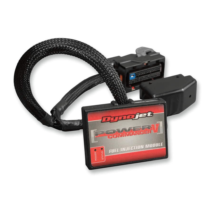
Power Commander
1
USB Cable
1
Installation Guide
2
Power Commander Decals
2
Dynojet Decals
2
Velcro strips
1
Alcohol swab
1
Posi-tap
THE IGNITION MUST BE TURNED
OFF BEFORE INSTALLATION!
THE LATEST POWER COMMANDER
SOFTWARE AND MAP FILES CAN BE
DOWNLOADED FROM OUR WEB SITE AT:
www.powercommander.com
2015 Yamaha YZ250FX & WR250F - PCV F/I - 1
Advertisement

Related Manuals for Dynojet POWER COMMANDER V


Summary of Contents for Dynojet POWER COMMANDER V
- Page 1 USB Cable Installation Guide FUEL AND IGNITION Power Commander Decals 2015 Yamaha YZ250FX & WR250F Dynojet Decals Velcro strips I n s t a l l a t i o n I n s t r u c t i o n s Alcohol swab Posi-tap THE IGNITION MUST BE TURNED...
-
Page 2: Usb Connection
POWER COMMANDER V INPUT ACCESSORY GUIDE ACCESSORY INPUTS Map - (Input 1 or 2) The PCV has the ability to hold 2 different base maps. You can switch on the fly between these two base maps when you hook up a switch to the MAP inputs. You can USB CONNECTION use any open/close type switch. The polarity of the wires is not important. When using the Autotune kit one position will hold a base map and the other position will let you activate the learning mode. When the switch is “CLOSED” Autotune will be activated. (Set to Switch Input #1 by default.) Shifter- (Input 1 or 2) These inputs are for use with the Dynojet quickshifter. Insert the wires from the CRANK Dynojet quickshifter into the SHIFTER inputs. ANALOG The polarity of the wires is not important. (Set to Switch Input #2 by default.) SPEED EXPANSION PORTS 1 & 2 INPUT 2 (Grnd) - Page 3 FIG.A Remove the seat, the air filter cover, and the radiator shrouds on both side of the bike (Fig. A). Remove the fuel tank. FIG.B Loosen the stock ECU from its mounting location by removing the two Remove Remove mounting bolts (Fig. B). FIG.C Remove Loosen the left side radiator by removing the two mounting bolts (Fig. C). This will allow easy access to the bike’s stock Crank Position Sensor connectors. Remove 22-071 www.powercommander.com 2015 Yamaha YZ250FX & WR250F - PCV F/I - 3...
- Page 4 FIG.D Unplug the stock wiring harness from the bike’s starter solenoid just right of Unplug the battery (Fig. D). FIG.E Use the stock battery strap to secure the PCV module to the top of the battery (Fig. E). The supplied Velcro strips could also be used to secure the PCV module if desired. If so, use the supplied alcohol swab to clean all surface areas prior to applying the Velcro adhesive. Secure the PCV ground wire with the small ring lug to the stock common ground on the underside of the frame cross-over bracket shown in Figure E.
- Page 5 FIG.G 11 Plug the PCV wiring harness in-line of the Fuel Injector and the stock wiring harness (Fig. G). FIG.H 12 Pull the rubber boot loose from around the stock ECU connector. Route the single unterminated GREY wire of the PCV wiring harness through the rubber boot. 13 Use the supplied Posi-tap to attach the PCV GREY wire to the stock YELLOW wire of the ECU connector (Fig. H). 14 Reinstall the rubber boot over the stock ECU connector and secure the ECU to its original mounting location by reinstalling the two bolts. FIG.J 15 Unplug the stock wiring harness from the Ignition Coil sub-connector (Fig. J). This is a pair of BLACK 2-pin connectors located just above the Ignition Coil. 22-071 www.powercommander.com 2015 Yamaha YZ250FX & WR250F - PCV F/I - 5...
- Page 6 FIG.K 16 Plug the pair of 2-pin PCV connectors with GREEN colored wires in-line of the stock Ignition Coil sub-harness connectors (Fig. K). 17 Continue routing the pair of PCV connectors with BROWN colored wires forward and left of the engine towards the left side radiator (previously loosened during step 4). FIG.L 18 On the left side of the frame, locate and unplug the stock connectors from the bike’s Crank Position Sensor (Fig. L). Unplug This is a GREY 2-pin connector pair. 19 Plug the pair of PCV connectors with BROWN colored wires in-line of the stock Crank Position Sensor connectors (Fig. M). 20 Make sure wiring harness routing is free and clear of any hot or moving parts. FIG.M Use ties to secure the wiring as necessary. 21 Reinstall the left radiator and the mounting bolts for it. Reinstall the fuel tank, radiator shrouds, air filter cover, and the seat. NOTE: The PCV comes premapped for a stock exhaust, stock air filter on the YZ250FX model. If you have a WR250F model make sure to download the appropriate map. 22-071 www.powercommander.com 2015 Yamaha YZ250FX & WR250F - PCV F/I - 6...
Need help?
Do you have a question about the POWER COMMANDER V and is the answer not in the manual?
Questions and answers