Advertisement
Quick Links
Advertisement

Related Manuals for AUDAC POW2


Summary of Contents for AUDAC POW2
- Page 1 POW2 Installation Manual www.audac.eu...
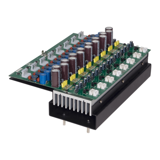
- Page 2 Introduction Matrix Power Amplifier Kit The POW2 is a sixteen channel power amplifier kit which is an optional device to be installed inside the R2 Multi-Zone Digital Audio Matrix and M2 Multi-Media Digital Audio Mixer devices. In their standard configuration, these matrix systems are equipped with 8 line level output channels whereto the appropriate amplifiers for your application can be connected.
-
Page 3: Package Contents
Package contents - Power amplifier module - Power supply unit with PFC - Loudspeaker output cables 200 mm (8 pcs) - Stereo shielded signal cable 420 mm (2 pcs) - Stereo shielded signal cable 460 mm (2 pcs) - Stereo shielded signal cable 500 mm (2 pcs) - Stereo shielded signal cable 540 mm (2 pcs) - Mute cable 400 mm - Power cable set Red / Black / Yellow... - Page 4 Step 3: For M2: Place one of the supplied ferrite cores around the flatcables coming from the USB and SD/MMC board on the front panel of the device. Step 4: Amplifier channel layout...
- Page 5 Attach the 8 loudspeaker output cables to the I/O board(s) of the system. Depending of the kind of system (R2 or M2) the output board will be different. The loudspeaker output cables should be connected to the large 4-pin connectors on the bottom side of the I/O board(s).
- Page 6 Align the cables to facilitate the placing of the amplifier module. Use cable ties to hold the signal cables together. Signal cables will go under the amplifier module whereas the output cables remain at the back of the unit. Step 6: Then place the amplifier inside the matrix housing and fix it by inserting and tightening four screws from the housings bottom side.
- Page 7 Make sure the right amplifier channel is connected to the corresponding connector on the I/O board. The connectors on the I/O board of the R2 are marked with the number of the corresponding channel. Note: Remember for R2 the I/O board is different, so please make sure you connect the right channels to each other:...
- Page 8 Step 8: Connect the mute (Anti plop) cable to the provided connector on the amplifier module and the small power supply (PowerDSP). Step 9: Power Supply unit Please check if the suppression coil is attached to the power cable. If it isn’t, please attache the supplied suppression coil first.
- Page 9 Place the power supply unit with PFC inside the matrix housing and fix it by inserting and tightening four screws from the housings bottom side. Step 10: Connect the mains (110V AC ~ 240 V AC) cable from the big power supply (Power supply unit with PFC) to the provided connector on the small power supply (PowerDSP).
- Page 10 Step 11: Connect the 28 Volts output (+28V, GND, -28V) of the big power supply to the amplifier module. Align the connected cables nicely and fasten them with Cable ties. Ensure the airflow of the fan is not blocked by cables.
- Page 11 (the active one and the spare one) by the T4AL/250V fuse and place the fuse holder back into the device. Finally, attach POW2 option sticker at the back of the device. POW2 option inside...
Need help?
Do you have a question about the POW2 and is the answer not in the manual?
Questions and answers