Table of Contents
Advertisement
Quick Links
Advertisement
Table of Contents

Related Manuals for GW Instek GCP-100


Summary of Contents for GW Instek GCP-100
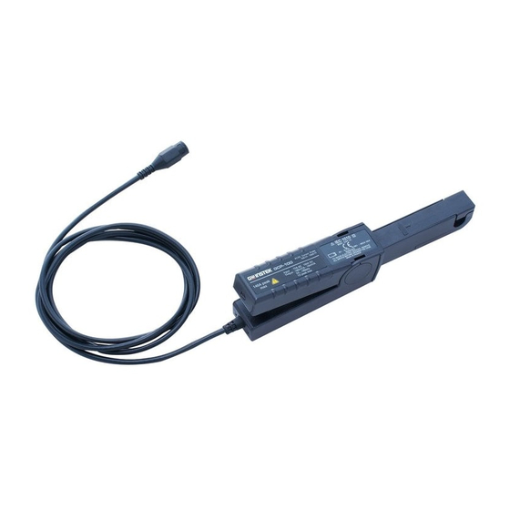
- Page 1 AC/DC Current Probe GCP-100 QUICK START GUIDE ISO-9001 CERTIFIED MANUFACTURER...
- Page 2 This manual contains proprietary information, which is protected by copyright. All rights are reserved. No part of this manual may be photocopied, reproduced or translated to another language without prior written consent of Good Will Corporation. The information in this manual was correct at the time of printing.
-
Page 3: Afety Instructions
Please use a separate collection facility or contact the supplier from which this instrument was purchased. Thank you for purchasing GCP-100 AC/DC current probe. To obtain the best possible service from your device: • Read this User’s manual carefully, •... -
Page 4: Electromagnetic Compatibility
• For your safety, ensure that the instruments used with your clamp are also in accordance with IEC 1010. LECTRICAL SAFETY Protection From Electric Shocks Instrument with double insulation or strengthened insulation in the part that is hand held in normal use, and with single insulation or additional insulation between the primary and the secondary output. -
Page 5: Battery Indicator
EATURES • The GCP-100 is a current probe for oscilloscope which uses a Hall effect cell for the measurement of DC or AC current without modification of the installation (without switching off the circuit) • It can measure currents from 50 mA to 100 A peak. It has 2... - Page 6 3. Resetting zero on the probe The thumbwheel makes it possible to reset the output voltage to zero. It is thus possible to overcome the different errors due to thermal shifts, the Earth’s magnetic field, the environment, and residual induction. 4.
-
Page 7: Mechanical Specifications
If necessary, recheck the origin of the graph, with the jaws not clamped around the conductor, and make the measurement again. PECIFICATIONS Mechanical Specifications Model GCP-100 Max. cable dimensions Ø 11.8 mm Jaw opening 12.5 mm maximum Dimension 231 x 67 x 36 mm win core lead (coaxial) 2m... -
Page 8: Electrical Specifications
Electrical Specifications Range Measurement extent Intrinsic error Range 100mV/A 50mA to 10A peak 3% R + 50mA Range 10mV/A 50mA to 40A peak 4% R + 50mA Range 10mV/A 40A to 100A peak Graph value below R: reading Typical noise level at output (peak-peak value) These specifications are given for an ambient temperature of 23°... - Page 9 ISTORTION MAGNITUDES • Battery voltage from 6.5 V to 10 V: ± 6 mA/V typical, ± 10 mA/V max. • Temperature from 0 to 50°C: ± 2000 ppm/°C max • Position of the conductor in the window (AC signal of frequency 1 kHz): max ±...
- Page 10 Repairs Repairs under or out of guarantee: please return the product to your distributor. PPENDICE Typical response curves for frequency and phase Shift measurement current : 1A peak Measurement current : 1A peak Different limiting examples of the response of the response of the Clamp...
Need help?
Do you have a question about the GCP-100 and is the answer not in the manual?
Questions and answers