Digital Equipment AlphaServer 1000 Service Manual
Hide thumbs
Also See for AlphaServer 1000:
- Owner's manual (213 pages) ,
- Rackmount owners manual (191 pages) ,
- Upgrade information (15 pages)

Related Manuals for Digital Equipment AlphaServer 1000


Summary of Contents for Digital Equipment AlphaServer 1000
- Page 1 AlphaServer 1000 Service Guide Order Number: EK–DTLSV–SV. B01 Digital Equipment Corporation Maynard, Massachusetts...
- Page 2 First Printing, February 1995 Second Printing, July 1995 Digital Equipment Corporation makes no representations that the use of its products in the manner described in this publication will not infringe on existing or future patent rights, nor do the descriptions contained in this publication imply the granting of licenses to make, use, or sell equipment or software in accordance with the description.
-
Page 3: Table Of Contents
Contents Preface ..........1 Troubleshooting Strategy Troubleshooting the System . - Page 4 3 Running System Diagnostics Running ROM-Based Diagnostics ....3–1 Command Summary ......3–2 Command Reference .
- Page 5 5–37 6 AlphaServer 1000 FRU Removal and Replacement AlphaServer 1000 FRUs ......6–1 Removal and Replacement ......
- Page 6 2–1 2–6 2–2 AlphaServer 1000 Memory Layout ....2–7 2–3 StorageWorks Disk Drive LEDs (SCSI) ... .
- Page 7 6–1 FRUs, Front Right ......6–4 FRUs, Rear Left ......6–2 6–5 6–3...
- Page 8 2–16 3–1 Summary of Diagnostic and Related Commands ..3–2 AlphaServer 1000 Fault Detection and Correction ..4–1 4–2 5–1 Listing the ARC Firmware Device Names ..
- Page 9 ISA Options ....... . 5–27 AlphaServer 1000 FRUs ......6–1 6–2...
-
Page 11: Preface
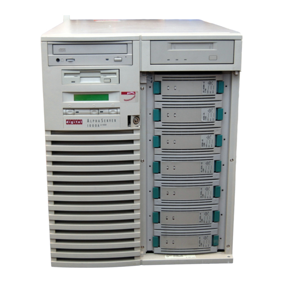
Preface This guide describes the procedures and tests used to service AlphaServer 1000 systems. AlphaServer 1000 systems use a deskside ‘‘wide-tower’’ enclosure. Intended Audience This guide is intended for use by Digital Equipment Corporation service personnel and qualified self-maintenance customers. -
Page 12: Related Documentation
In command descriptions, braces containing items separated by commas imply mutually exclusive items. Circled numbers provide a link between examples and text. Related Documentation • AlphaServer 1000 Owner’s Guide, EK-DTLSV-OG • DEC Verifier and Exerciser Tool User’s Guide, AA-PTTMA-TE • Guide to Kernel Debugging, AA-PS2TA-TE •... -
Page 13: Troubleshooting Strategy
Troubleshooting Strategy This chapter describes the troubleshooting strategy for AlphaServer 1000 systems. • Section 1.1 provides questions to consider before you begin troubleshooting an AlphaServer 1000 system. • Tables 1–1 through 1–5 provide a diagnostic flow for each category of system problem. -
Page 14: Problem Categories
1.1.1 Problem Categories System problems can be classified into the following five categories. Using these categories, you can quickly determine a starting point for diagnosis and eliminate the unlikely sources of the problem. 1. Power problems (Table 1–1) 2. No access to console mode (Table 1–2) 3. -
Page 15: Diagnostic Flow For Power Problems
Table 1–1 Diagnostic Flow for Power Problems Symptom Action System does not power on. • Check the power source and power cord. • Check that the system’s top cover is properly secured. A safety interlock switch shuts off power to the system if the top cover is removed. •... -
Page 16: Diagnostic Flow For Problems Getting To Console Mode
Table 1–2 Diagnostic Flow for Problems Getting to Console Mode Symptom Action Power-up screen is not displayed. Interpret the error beep codes at power-up (Section 2.1) for a failure detected during self-tests. Check that the keyboard and monitor are properly connected and turned on. -
Page 17: Diagnostic Flow For Problems Reported By The Console Program
Table 1–3 Diagnostic Flow for Problems Reported by the Console Program Symptom Action Power-up tests do not complete. Interpret the error beep codes at power-up (Section 2.1) and check the power-up screen (Section 2.2) for a failure detected during self-tests. If the power-up display stops on e6, an EISA or PCI board is causing the system to hang. -
Page 18: Diagnostic Flow For Boot Problems
Table 1–4 Diagnostic Flow for Boot Problems Symptom Action System cannot find boot device. Check the system configuration for the correct device parameters (node ID, device name, and so on). • For DEC OSF/1 and OpenVMS, use the show config show device commands (Section 5.1). -
Page 19: Service Tools And Utilities
Table 1–5 Diagnostic Flow for Errors Reported by the Operating System Symptom Action System is hung or has crashed. Examine the crash dump file. Refer to OpenVMS AXP Alpha System Dump Analyzer Utility Manual for information on how to interpret OpenVMS crash dump files. - Page 20 RECOMMENDED USE: ROM-based diagnostics are the primary means of testing the console environment and diagnosing the CPU, memory, Ethernet, I/O buses, and SCSI subsystems. Use ROM-based diagnostics in the acceptance test procedures when you install a system, add a memory module, or replace the following: CPU module, memory module, motherboard, I/O bus device, or storage device.
-
Page 21: Information Services
Crash Dumps For fatal errors, such as fatal bugchecks, DEC OSF/1 and OpenVMS operating systems will save the contents of memory to a crash dump file. RECOMMENDED USE: Crash dump files can be used to determine why the system crashed. To save a crash dump file for analysis, you need to know the proper system settings. -
Page 23: Power-Up Diagnostics And Display
Power-Up Diagnostics and Display This chapter provides information on how to interpret error beep codes and the power-up display on the console screen. In addition, a description of the power-up and firmware power-up diagnostics is provided as a resource to aid in troubleshooting. -
Page 24: Interpreting Error Beep Codes
2.1 Interpreting Error Beep Codes If errors are detected at power-up, audible beep codes are emitted from the system. For example, if the SROM code could not find any good memory, you would hear a 1-3-3 beep code (one beep, a pause, a burst of three beeps, a pause, and another burst of three beeps). -
Page 25: Srom Memory Power-Up Tests
Table 2–1 (Cont.) Interpreting Error Beep Codes Beep Code Problem Corrective Action 1-3-3 No usable memory detected. Verify that the memory modules are properly seated and try powering up again. Swap bank 0 memory with known good memory and run SROM memory tests at power- up (Section 2.1.1). -
Page 26: Srom Memory Tests, Cpu Jumper J1
Test duration: Approximately 10 seconds per 8 megabytes of memory. Figure 2–2 shows the bank and SIMM layout for AlphaServer 1000 systems. After determining the bad SIMM, refer to Chapter 6 for instructions on replacing FRUs. Note: The memory tests do not test the ECC SIMMs. If the operating system logs five or more single-bit correctible... - Page 27 Test duration: Approximately 2 seconds per 8 megabytes of memory. Figure 2–2 shows the bank and SIMM layout for AlphaServer 1000 systems. After determining the bad SIMM, refer to Chapter 6 for instructions on replacing FRUs. Note: The memory tests do not test the ECC SIMMs. If the operating system logs five or more single-bit correctible...
-
Page 28: Jumper J1 On The Cpu Daughter Board
Figure 2–1 Jumper J1 on the CPU Daughter Board MA00328 Bank Jumper Setting Standard boot setting (default) Mini-console setting: Internal use only SROM CacheTest: backup cache test SROM BCacheTest: backup cache and memory test SROM memTest: memory test with backup and data cache disabled SROM memTestCacheOn: memory test with backup and data cache enabled SROM BCache Tag Test: backup cache tag test Fail-Safe Loader setting: selects fail-safe loader firmware... -
Page 29: Power-Up Screen
Figure 2–2 AlphaServer 1000 Memory Layout SIMM 1 SIMM 3 Bank 3 SIMM 0 SIMM 2 SIMM 1 SIMM 3 Bank 2 SIMM 0 SIMM 2 SIMM 1 SIMM 3 Bank 1 SIMM 0 SIMM 2 SIMM 1 SIMM 3... -
Page 30: Console Event Log
Use the arrow keys to select, then press Enter. 2.2.1 Console Event Log AlphaServer 1000 systems maintain a console event log consisting of status messages received during power-on self-tests. If problems occur during power-up, standard error messages indicated by asterisks (***) may be embedded in the console event log. -
Page 31: Mass Storage Problems Indicated At Power-Up
2.3 Mass Storage Problems Indicated at Power-Up Mass storage failures at power-up are usually indicated by read fail messages. Other problems are indicated by storage devices missing from the show config display. • Table 2–3 provides information for troubleshooting mass storage problems indicated at power-up or storage devices missing from the show config display. - Page 32 Table 2–3 (Cont.) Mass Storage Problems Problem Symptom Corrective Action SCSI bus length Drives may disappear A SCSI bus extended to the exceeded intermittently from the internal StorageWorks shelf with show config show the backplane configured as a device displays. single bus, cannot be extended outside of the enclosure.
-
Page 33: Storage Device Leds
Table 2–4 Troubleshooting Problems with SWXCR-xx RAID Controller Symptom Action Some RAID drives do not appear Valid configured RAID logical drives will appear as show device d on the display. DRA0–DRAn, not as DKn. Configure the drives by running the RAID Configuration Utility (RCU). Follow the instructions in the StorageWorks RAID Array 200 Subsystem Family Installation and Configuration Guide, EK-SWRA2-IG. -
Page 34: Storageworks Disk Drive Leds (Scsi)
For information on other storage devices, refer to the documentation provided by the manufacturer or vendor. Figure 2–3 StorageWorks Disk Drive LEDs (SCSI) Activity Fault MA00329 Figure 2–4 Floppy Drive Activity LED Activity LED MA00330 2–12 Power-Up Diagnostics and Display... -
Page 35: Cd-Rom Drive Activity Led
Figure 2–5 CD–ROM Drive Activity LED Activity LED MA00333 Power-Up Diagnostics and Display 2–13... -
Page 36: Eisa Bus Problems Indicated At Power-Up
2.5 EISA Bus Problems Indicated at Power-Up EISA bus failures at power-up are usually indicated by the following messages displayed during power-up: EISA Configuration Error. Run the EISA Configuration Utility. Run the EISA Configuration Utility (ECU) (Section 5.4) when this message is displayed. -
Page 37: Additional Eisa Troubleshooting Tips
• The CFG files supplied with the option you want to install may not work on AlphaServer 1000 systems. Some CFG files call overlay files that are not required on this system or may reference inappropriate system resources, for example, BIOS addresses. Contact the option vendor to obtain the proper CFG file. -
Page 38: Pci Bus Problems Indicated At Power-Up
2.6 PCI Bus Problems Indicated at Power-Up PCI bus failures at power-up are usually indicated by the inability of the system to see the device. Table 2–6 provides steps for troubleshooting PCI bus problems. Use the table to diagnose the likely cause of the problem. Note Some PCI devices do not implement PCI parity, and some have a parity- generating scheme in which parity is sometimes incorrect or is not... -
Page 39: Fail-Safe Loader
2.7 Fail-Safe Loader The fail-safe loader (FSL) allows you to attempt to recover when one of the following is the cause of a problem getting to the console program under normal power-up: • A power failure or accidental power down during a firmware upgrade •... -
Page 40: Jumper J1 On The Cpu Daughter Board
Figure 2–6 Jumper J1 on the CPU Daughter Board MA00328 Bank Jumper Setting Standard boot setting (default) Mini-console setting: Internal use only SROM CacheTest: backup cache test SROM BCacheTest: backup cache and memory test SROM memTest: memory test with backup and data cache disabled SROM memTestCacheOn: memory test with backup and data cache enabled SROM BCache Tag Test: backup cache tag test Fail-Safe Loader setting: selects fail-safe loader firmware... -
Page 41: Power-Up Sequence
Serial ROM diagnostics – Console firmware-based diagnostics Caution The AlphaServer 1000 enclosure will not power up if the top cover is not securely attached. Removing the top cover will cause the system to shut down. 2.8.1 AC Power-Up Sequence The following power-up sequence occurs when AC power is applied to the system (system is plugged in) or when electricity is restored after a power outage: 1. -
Page 42: Dc Power-Up Sequence
2.8.2 DC Power-Up Sequence DC power is applied to the system with the DC On/Off button on the operator control panel. A summary of the DC power-up sequence follows: 1. When the DC On/Off button is pressed, the power supply checks for a POK_H condition. -
Page 43: Console Firmware-Based Diagnostics
4. Configure the memory in the system and test only the first 4 MB of memory. If there is more than one memory module of the same size, the lowest numbered memory module (one closest to the CPU) is tested first. If the memory test fails, the failing bank is mapped out and memory is reconfigured and re-tested. - Page 44 5. Enter console mode or boot the operating system. This action is determined by the auto_action environment variable. If the environment variable is set to NT, the ARC console is loaded os_type into memory, and control is passed to the ARC console. 2–22 Power-Up Diagnostics and Display...
-
Page 45: Running System Diagnostics
AlphaServer 1000 RBDs rely on exerciser modules, rather than functional tests, to isolate errors. The exercisers are designed to run concurrently, providing a maximum bus interaction between the console drivers and the target devices. -
Page 46: Command Summary
3.2 Command Summary Table 3–1 provides a summary of the diagnostic and related commands. Table 3–1 Summary of Diagnostic and Related Commands Command Function Reference Acceptance Testing test Quickly tests the core system. The test command Section 3.3.1 is the primary diagnostic for acceptance testing and console environment diagnosis. -
Page 47: Command Reference
Table 3–1 (Cont.) Summary of Diagnostic and Related Commands Command Function Reference Loopback Testing test lb Conducts loopback tests for COM2 and the parallel Section 3.3.1 port in addition to quick core system tests. netew Runs external mop loopback tests for specified EISA- Section 3.3.4 or PCI-based ew* (DECchip 21040, TULIP) Ethernet ports. -
Page 48: Test
3.3.1 test command runs firmware diagnostics for the entire core system. The test tests are run concurrently in the background. Fatal errors are reported to the console terminal. command should be used in conjunction with the command to cat el test examine test/error information reported to the console event log. - Page 49 5. VGA console tests. These tests are run only if the console environment variable is set to ‘‘serial.’’ The VGA console test displays rows of the letter ‘‘H’’. Synopsis: test [lb] Argument: [lb] The loopback option includes console loopback tests for the COM2 serial port and the parallel port during the test sequence.
- Page 50 Program Device Pass Hard/Soft Bytes Written Bytes Read -------- ------------ ------------ ------ --------- ------------- ------------- 00000001 idle system 0000002d exer_kid tta1 0000003d nettest era0.0.0.2.1 1376 1376 00000045 memtest memory 424673280 424673280 00000052 exer_kid dka100.1.0.6 2688512 00000053 exer_kid dka200.2.0.6 922624 >>> kill_diags >>>...
-
Page 51: Cat El And More El
3.3.2 cat el and more el commands display the current contents of the console cat el more el event log. Status and error messages (if problems occur) are logged to the console event log at power-up, during normal system operation, and while running system tests. -
Page 52: Memory
3.3.3 memory command tests memory by running a memory exerciser each time the memory command is entered. The exercisers are run in the background and nothing is displayed unless an error occurs. The number of exercisers, as well as the length of time for testing, depends on the context of the testing. - Page 53 Example with a memory compare error indicating bad SIMMs. >>> memory >>> memory >>> memory *** Hard Error - Error #44 - Memory compare error Diagnostic Name Device Pass Test Hard/Soft 1-JAN-2066 memtest 000000c8 brd0 12:00:01 Expected value: 00000004 Received value: 80000001 Failing addr: 800001c *** End of Error ***...
-
Page 54: Netew
3.3.4 netew command is used to run MOP loopback tests for any EISA- or PCI- netew based ew* (DECchip 21040, TULIP) Ethernet ports. The command can also be used to test a port on a ‘‘live’’ network. The loopback tests are set to run continuously (-p pass_count set to 0). Use the command (or ) to terminate an individual diagnostic or the kill... - Page 55 Testing an Ethernet Port: >>> netew >>> show_status Program Device Pass Hard/Soft Bytes Written Bytes Read -------- ------------ ------------ ------ --------- ------------- ------------- 00000001 idle system 000000d5 nettest ewa0.0.0.0.0 308672 308672 >>> kill_diags >>> Running System Diagnostics 3–11...
-
Page 56: Network
3.3.5 network command is used to run MOP loopback tests for any EISA- or PCI- network based er* (DEC 4220, LANCE) Ethernet ports. The command can also be used to test a port on a ‘‘live’’ network. The loopback tests are set to run continuously (-p pass_count set to 0). Use the command (or ) to terminate an individual diagnostic or the kill... - Page 57 Testing an Ethernet Port: >>> network >>> show_status Program Device Pass Hard/Soft Bytes Written Bytes Read -------- ------------ ------------ ------ --------- ------------- ------------- 00000001 idle system 000000d5 nettest era0.0.0.0.0 308672 308672 >>> kill_diags >>> Running System Diagnostics 3–13...
-
Page 58: Net -S
3.3.6 net -s command displays the MOP counters for the specified Ethernet port. net -s Synopsis: net -s ewa0 Example: >>> net -s ewa0 Status counts: ti: 72 tps: 0 tu: 47 tjt: 0 unf: 0 ri: 70 ru: 0 rps: 0 rwt: 0 at: 0 fd: 0 lnf: 0 se: 0 tbf: 0 tto: 1 lkf: 1 ato: 1 nc: 71 oc: 0 MOP BLOCK:... -
Page 59: Net -Ic
3.3.7 net -ic command initializes the MOP counters for the specified Ethernet net -ic port. Synopsis: net -ic ewa0 Example: >>> net -ic ewa0 >>> net -s ewa0 Status counts: ti: 72 tps: 0 tu: 47 tjt: 0 unf: 0 ri: 70 ru: 0 rps: 0 rwt: 0 at: 0 fd: 0 lnf: 0 se: 0 tbf: 0 tto: 1 lkf: 1 ato: 1 nc: 71 oc: 0 MOP BLOCK:... -
Page 60: Kill And Kill_Diags
3.3.8 kill and kill_diags commands terminate diagnostics that are currently kill kill_diags executing . Note A serial loopback connector (12-27351-01) must be installed on the COM2 serial port for the command to successfully terminate system kill_diags tests. • command terminates a specified process. kill •... -
Page 61: Show_Status
3.3.9 show_status command reports one line of information per executing show_status diagnostic. The information includes ID, diagnostic program, device under test, error counts, passes completed, bytes written, and bytes read. Many of the diagnostics run in the background and provide information only if an error occurs. -
Page 62: Acceptance Testing And Initialization
3.4 Acceptance Testing and Initialization Perform the acceptance testing procedure listed below after installing a system or whenever adding or replacing the following: Memory modules Motherboard CPU daughter board Storage devices EISA or PCI options 1. Run the RBD acceptance tests using the command. -
Page 63: Error Log Analysis
DECevent Translation and Reporting Utility available with OpenVMS and Digital UNIX. 4.1 Fault Detection and Reporting Table 4–1 provides a summary of the fault detection and correction components of AlphaServer 1000 systems. Generally, PALcode handles exceptions as follows: • The PALcode determines the cause of the exception. -
Page 64: Machine Check/Interrupts
Table 4–1 AlphaServer 1000 Fault Detection and Correction Component Fault Detection/Correction Capability KN22A Processor Module DECchip 21064 and 21064A Contains error detection and correction (EDC) logic for microprocessors data cycles. There are check bits associated with all data entering and exiting the 21064(A) microprocessor. A single- bit error on any of the four longwords being read can be corrected (per cycle). - Page 65 System Machine Check (SCB: 660) A system machine check is a system-detected error, external to the DECchip 21064 microprocessor and possibly not related to the activities of the CPU. These errors are specific to AlphaServer 1000 systems. Fatal errors: •...
-
Page 66: Error Logging And Event Log Entry Format
Single-bit Dstream ECC error • System transaction terminated with CACK_SERR System Machine Check (SCB: 620) These errors (non-fatal) are AlphaServer 1000-specific correctable errors. These errors result in the generation of the correctable machine check logout frame: • Correctable read errors •... -
Page 67: Event Record Translation
4.3 Event Record Translation Systems running Digital UNIX and OpenVMS operating systems use the DECevent management utility to translate events into ASCII reports derived from system event entries (bit-to-text translations). The DECevent utility has the following features relating to the translation of events: •... -
Page 68: Digital Unix Translation Using Decevent
4.3.2 Digital UNIX Translation Using DECevent The kernel error log entries are translated from binary to ASCII using the dia command. To invoke the DECevent utility, enter dia command. Format: dia [-a -f infile[ . . . ]] Example: % dia -t s:14-jun-1995:10:00 For more information on generating error log reports using DECevent, refer to DECevent Translation and Reporting Utility for Digital UNIX User and Reference Guide. -
Page 69: System Configuration And Setup
System Configuration and Setup This chapter provides configuration and setup information for AlphaServer 1000 systems and system options. • Section 5.1 describes how to examine the system configuration using the console firmware. – Section 5.1.1 describes the function of the two firmware interfaces used with AlphaServer 1000 systems. -
Page 70: Verifying System Configuration
5.1 Verifying System Configuration Figure 5–1 illustrates the system architecture for AlphaServer 1000 systems. Figure 5–1 System Architecture: AlphaServer 1000 PCI-EISA Flash Buffers Bridge CPU Card SROM 21064 EISA Slots EISA Slots PCI Slots EISA Slots Real Bcache Time Clock... - Page 71 SRM Command Line Interface Systems running DEC OSF/1 or OpenVMS access the SRM firmware through a command line interface (CLI). The CLI is a UNIX style shell that provides a set of commands and operators, as well as a scripting facility. The CLI allows you to configure and test the system, examine and alter system state, and boot the operating system.
-
Page 72: Switching Between Interfaces
5.1.2 Switching Between Interfaces For a few procedures it is necessary to switch from one console interface to the other. • command is run from the SRM interface. test • The EISA Configuration Utility (ECU) and the RAID Configuration Utility (RCU) are run from the ARC interface. -
Page 73: Display Hardware Configuration
5.1.3.1 Display Hardware Configuration The hardware configuration display provides the following information: • The first screen displays the boot devices. • The second screen displays processor information, the amount of memory installed, and the type of video card installed. • The third and fourth screens display information about the adapters installed in the system’s EISA and PCI slots. -
Page 74: Sample Hardware Configuration Display
Table 5–2 (Cont.) ARC Firmware Device Names Name Description scsi(0)disk(0)rdisk(0) The scsi( ) devices are SCSI disk or CD–ROM devices. scsi(0)cdrom(5)fdisk(0) These examples represent installed SCSI devices. The disk drives are set to SCSI ID 0, and the CD–ROM drive is set to SCSI ID 5. -
Page 75: Set Default Variables
Example 5–1 (Cont.) Sample Hardware Configuration Display Slot Device Identifier Other DEC2A01 Disk ADP0001 Network DEC4220 Network DEC3002 Network DEC4250 Display CPQ3011 Disk FLOPPY Press any key to continue... Wednesday, 8-31-1994 10:51:32 AM PCI slot information: Bus Virtual Slot Function Vendor Device Revision Device type 1000 SCSI 8086... -
Page 76: Arc Firmware Environment Variables
Table 5–3 lists and explains the default ARC firmware environment variables. Table 5–3 ARC Firmware Environment Variables Variable Description The default floppy drive. The default value is eisa( )disk( )fdisk( ). AUTOLOAD The default startup action, either YES (boot) or NO or undefined (remain in Windows NT firmware). -
Page 77: Verifying Configuration: Srm Console Commands For Dec Osf/1 And Openvms
5.1.4 Verifying Configuration: SRM Console Commands for DEC OSF/1 and OpenVMS The following SRM console commands are used to verify system configuration on DEC OSF/1 and OpenVMS systems: • (Section 5.1.4.1)—Displays the buses on the system and the show config devices found on those buses. - Page 78 Synopsis: show config Example: >>> show config Firmware SRM Console: V1.1-1 ARC Console: 3.5-14 PALcode: VMS PALcode X5.55, OSF PALcode X1.35-53 Serial Rom: Processor DECchip (tm) 21064-2 MEMORY 48 Meg of System Memory Bank 0 = 16 Mbytes(4 MB Per Simm) Starting at 0x00000000 Bank 1 = 16 Mbytes(4 MB Per Simm) Starting at 0x01000000 Bank 2 = 16 Mbytes(4 MB Per Simm) Starting at 0x02000000 Bank 3 = No Memory Detected...
-
Page 79: Show Device
5.1.4.2 show device show device command displays the devices and controllers in the system. The device name convention is shown in Figure 5–2. Figure 5–2 Device Name Convention dka0.0.0.0.0 Hose Number: 0 PCI_0 (32-bit PCI); 1 EISA; 2 PCI_1 Slot Number: For EISA options---Correspond to EISA card cage slot numbers (1--*) For PCI options---Slot 0 = Ethernet adapter (EWA0) or reserved on AlphaServer 2000 systems. -
Page 80: Show Memory
Example: >>> show device dka400.4.0.6.0 DKA400 RRD43 2893 dva0.0.0.0.1 DVA0 era0.0.0.2.1 ERA0 08-00-2B-BC-93-7A pka0.7.0.6.0 PKA0 SCSI Bus ID 7 >>> Console device name Node name (alphanumeric, up to 6 characters) Device type Firmware version (if known) 5.1.4.3 show memory show memory command displays information for each bank of memory in the system. -
Page 81: Environment Variables Set During System Configuration
show envar Arguments: envar The name of the environment variable to be modified. value The value that is assigned to the environment variable. This may be an ASCII string. Options: -default Restores variable to its default value. -integer Creates variable as an integer. -string Creates variable as a string (default). - Page 82 Table 5–4 (Cont.) Environment Variables Set During System Configuration Variable Attributes Function bootdef_dev The device or device list from which booting is to be attempted, when no path is specified on the command line. Set at factory to disk with Factory Installed Software;...
- Page 83 Table 5–4 (Cont.) Environment Variables Set During System Configuration Variable Attributes Function console Sets the device on which power-up output is displayed. GRAPHICS—Sets the power-up output to be displayed at a graphics terminal or device connected to the VGA module at the rear of the system.
- Page 84 Table 5–4 (Cont.) Environment Variables Set During System Configuration Variable Attributes Function os_type Sets the default operating system. ‘‘vms’’ or ‘‘osf’’—Sets system to boot the SRM firmware. ‘‘nt’’—Sets system to boot the ARC firmware. pci_parity Disables or enables parity checking on the PCI bus. ‘‘on’’—Enables parity checking for all devices on the PCI bus.
-
Page 85: System Bus Options
Note Whenever you use the command to reset an environment variable, you must initialize the system to put the new setting into effect. Initialize the system by entering the init command or pressing the Reset button. 5.2 System Bus Options The system bus interconnects the CPU and memory modules. -
Page 86: Card Cages And Bus Locations
Figure 5–3 Card Cages and Bus Locations VGA Jumper Bank 3 Bank 2 Bank 1 Bank 0 ECC Banks CPU Daughter Board Option Slots PCI or EISA/ISA Option Slots E14 E78 EISA/ISA NVRAM TOY Option Slots Clock Chip NVRAM Chip MA00334 Note If the top EISA connector is used (slot 8), the bottom PCI slot (slot 11) -
Page 87: Cpu Daughter Board
SROM code (SROM tests are controlled by jumper J6 on the CPU daughter board) 5.2.2 Memory Modules AlphaServer 1000 systems can support from 16 megabytes to 512 megabytes of memory. Memory options consist of five single in-line memory modules (SIMMs) and are available in the following variations: •... -
Page 88: Motherboard
Table 5–5 Operating System Memory Requirements Operating System Memory Requirements DEC OSF/1 and 32 MB minimum; 64 MB recommended OpenVMS Windows NT 16 MB minimum; 32 MB recommended Windows NT Server 32 MB minimum; 64 MB recommended Figure 5–4 Memory Layout on the Motherboard SIMM 1 SIMM 3 Bank 3... -
Page 89: Eisa Bus Options
The EISA bus is a superset of the well-established ISA bus and has been designed to be backward compatible with 16-bit and 8-bit architecture. Therefore, ISA modules can be used in AlphaServer 1000 systems, provided the operating system supports the device. -
Page 90: Identifying Isa And Eisa Options
Up to eight ISA (or EISA) modules can reside in the EISA bus portion of the card cage. Refer to Section 5.6 for information on using the EISA Configuration Utility (ECU) to configure ISA options. Warning: For protection against fire, only modules with current- limited outputs should be used. -
Page 91: Before You Run The Ecu
The ECU is supplied on the two System Configuration Diskettes shipped with the system. Make a backup copy of the system configuration diskette and keep the original in a safe place. Use the backup copy when you are configuring the system. The system configuration diskette must have the volume label ‘‘SYSTEMCFG.’’... -
Page 92: How To Start The Ecu
5.6.2 How to Start the ECU Complete the following steps to run the ECU: 1. Invoke the console firmware. • For systems running Windows NT—Shut down the operating system or power up to the console Boot menu. • For systems running OpenVMS or DEC OSF/1—Shut down the operating system and press the Halt button or power up with the Halt button set to the ‘‘in’’... -
Page 93: Configuring Eisa Options
Note If you are configuring only EISA options, do not perform Step 2 of the ECU, ‘‘Add or remove boards.’’ (EISA boards are recognized and configured automatically.) • If you are configuring an EISA bus that contains both ISA and EISA options, refer to Table 5–7. -
Page 94: Configuring Isa Options
Table 5–6 Summary of Procedure for Configuring EISA Bus (EISA Options Only) Step Explanation Install EISA option. Use the instructions provided with the EISA option. Power up and run ECU. If the ECU locates the required CFG configuration files, it displays the main menu. -
Page 95: Summary Of Procedure For Configuring Eisa Bus With Isa Options
Table 5–7 Summary of Procedure for Configuring EISA Bus with ISA Options Step Explanation Install or move EISA Use the instructions provided with the EISA option. ISA option. Do not install ISA boards are installed after the configuration process is boards. -
Page 96: Pci Bus Options
5.8 SCSI Buses A Fast SCSI-2 adapter on the system motherboard provides a single-ended SCSI bus for AlphaServer 1000 systems. All tabletop or rackmounted SCSI-2 devices are supported through EISA- or PCI-based SCSI adapters. Use the following rules to determine whether a device can be used on your system: •... -
Page 97: Single Controller (On-Board) Configurations
This bus can be extended to the internal StorageWorks shelf or an external expander to support up to seven drives. The AlphaServer 1000 deskside ‘‘wide tower’’ supports an internal StorageWorks shelf that can support up to seven SCSI disk drives in a dual-bus configuration. -
Page 98: Single Controller Configuration With Dual Bus Storageworks Shelf
Figure 5–7 Single Controller Configuration with Dual Bus StorageWorks Shelf 17-03959-01 Bus ID 4 Bus ID 5 17-03962-01 MA00301 5–30 System Configuration and Setup... -
Page 99: Single Controller Configuration With Single Bus Storageworks Shelf
Figure 5–8 Single Controller Configuration with Single Bus StorageWorks Shelf 17-03959-01 Bus ID 4 Bus ID 5 17-03960-01 17-03962-01 MA00302 System Configuration and Setup 5–31... -
Page 100: Multiple Controller Configurations
5.8.2 Multiple Controller Configurations Figure 5–9 shows a configuration using two controllers. In this configuration the StorageWorks shelf is configured as a single bus. Figure 5–10 shows a configuration using two controllers. In this configuration the StorageWorks shelf is configured as a dual bus. Figure 5–9 Dual Controller Configuration with Single Bus StorageWorks Shelf 17-03959-01 Bus ID 4... -
Page 101: Dual Controller Configuration With Dual Bus Storageworks Shelf
Figure 5–10 Dual Controller Configuration with Dual Bus StorageWorks Shelf 17-03959-01 Bus ID 4 Bus ID 5 17-03960-02 17-03962-01 17-03962-02 12-41667-02 17-03960-02 17-03962-02 Bus A Bus B 12-41667-02 MA00304 System Configuration and Setup 5–33... -
Page 102: Power Supply Configurations
AlphaServer 1000 systems offer added reliability with redundant power options, as well as UPS options. The power supplies for AlphaServer 1000 systems support two different modes of operation. In addition, UPS options are available. Refer to Figure 5–11. Power supply modes of operation: 1. -
Page 103: Power Supply Configurations
Figure 5–11 Power Supply Configurations Single Redundant 400 Watts DC or Less 400 Watts DC or Less MA00335 System Configuration and Setup 5–35... -
Page 104: Power Supply Cable Connections
Figure 5–12 Power Supply Cable Connections Signal/Misc. Harness + 3.3V Harness (22-Pin/15-Pin) (20-Pin) + 5V Harness (24-Pin) 17-03969-01 Current Sharing Harness (3-Pin) Storage Harness (12-Pin) + 5V Harness (24-Pin) + 3.3V Harness (20-Pin) Signal/Misc. Harness (15-Pin) MA00355 5–36 System Configuration and Setup... -
Page 105: Console Port Configurations
5.10 Console Port Configurations Power-up information is typically displayed on the system’s console terminal. The console terminal may be either a graphics terminal or a serial terminal (connected through the COM1 serial port). The setting of the console environment variable determines where the system will display power-up output. - Page 106 Using a VGA Controller Other than the Standard On-Board VGA When the system is configured to use a PCI- or EISA-based VGA controller instead of the standard on-board VGA (CIRRUS), consider the following: • The on-board CIRRUS VGA options must be set to disabled through the ECU. •...
-
Page 107: Alphaserver 1000 Fru Removal And Replacement
AlphaServer 1000 FRU Removal and Replacement This chapter describes the field-replaceable unit (FRU) removal and replacement procedures for AlphaServer 1000 systems, which use a deskside ‘‘wide-tower’’ enclosure. • Section 6.1 lists the FRUs for AlphaServer 1000-series systems. • Section 6.2 provides the removal and replacement procedures for the FRUs. -
Page 108: Floppy Drive Cable (34-Pin)
54-23297-01 200 MHz CPU daughter board Section 6.2.2 54-23297-03 233 MHz CPU daughter board Section 6.2.2 Fans 70-31350-01 92 mm fan Section 6.2.3 70-31351-01 120 mm fan Section 6.2.3 (continued on next page) 6–2 AlphaServer 1000 FRU Removal and Replacement... - Page 109 Serial port loopback connector (9-pin) 12-22196-01 Ethernet thickwire loopback connector 12-35619-01 Ethernet twisted-pair loopback connector H8223 Ethernet BNC T connector H8225 Ethernet BNC terminator (2) 74-50062-01 Key for door (continued on next page) AlphaServer 1000 FRU Removal and Replacement 6–3...
-
Page 110: Frus, Front Right
Tape Drive Assembly Switch CDROM Drive Floppy Drive Floppy Drive Cable OCP Module OCP Cable Current Sharing Cable Hard Disk Drives Power Supply Power Supply Storage Harness StorageWorks Backplane StorageWorks Jumper Cable MA00320 6–4 AlphaServer 1000 FRU Removal and Replacement... -
Page 111: Frus, Rear Left
Figure 6–2 FRUs, Rear Left Memory Upper Fan SCSI Cables Speaker Lower Fan Power Cord SCSI Multinode Cable CPU Daughter Board Motherboard NVRAM Chip (E14) MA00321 NVRAM Toy Clock Chip (E78) AlphaServer 1000 FRU Removal and Replacement 6–5... -
Page 112: Removal And Replacement
6.2 Removal and Replacement This section describes the procedures for removing and replacing FRUs for AlphaServer 1000 systems, which use the deskside ‘‘wide-tower’’ enclosure. Caution: Before removing the top cover and side panels: 1. Perform an orderly shutdown of the operating system. -
Page 113: Removing Top Cover And Side Panels
Figure 6–4 Removing Top Cover and Side Panels Top Cover Release Latch MA00300 AlphaServer 1000 FRU Removal and Replacement 6–7... -
Page 114: Cables
6.2.1 Cables This section shows the routing for each cable in the system. Figure 6–5 Floppy Drive Cable (34-Pin) 17-03970-02 MA00336 6–8 AlphaServer 1000 FRU Removal and Replacement... - Page 115 Figure 6–6 OCP Module Cable (10-Pin) 17-03971-01 MA00337 AlphaServer 1000 FRU Removal and Replacement 6–9...
-
Page 116: Power Cord Order Numbers
Central Europe (Aus, Bel, BN19C-2E 17-00199-21 Fra, Ger, Fin, Hol, Nor, Swe, Por, Spa) U.K., Ireland BN19A-2E 17-00209-15 Switzerland BN19E-2E 17-00210-13 Denmark BN19K-2E 17-00310-08 Italy BN19M-2E 17-00364-18 India, South Africa BN19S-2E 17-00456-16 Israel BN18L-2E 17-00457-16 6–10 AlphaServer 1000 FRU Removal and Replacement... - Page 117 Figure 6–8 Power Supply Current Sharing Cable (3-Pin) MA00339 AlphaServer 1000 FRU Removal and Replacement 6–11...
- Page 118 + 5V Harness (24-Pin) + 3.3V Harness (20-Pin) Signal/Misc. Harness (15-Pin) MA00351 The power supply DC cable assembly contains the following cables: • Power supply signal/misc cable (15-pin) • Power supply +5V cable (24-pin) 6–12 AlphaServer 1000 FRU Removal and Replacement...
- Page 119 • Power supply +3.3V (20-pin) Figure 6–10 Power Supply Storage Harness (12-Pin) 17-03969-01 Storage Harness (12-Pin) MA00352 AlphaServer 1000 FRU Removal and Replacement 6–13...
- Page 120 Figure 6–11 Interlock/Server Management Cable (2-pin) J254 MA00370 6–14 AlphaServer 1000 FRU Removal and Replacement...
- Page 121 Figure 6–12 Internal StorageWorks Jumper Cable (50-Pin) 17-03960-01 MA00342 AlphaServer 1000 FRU Removal and Replacement 6–15...
-
Page 122: Scsi (J15 Storageworks Shelf To Bulkhead Connector Or Bulkhead To Multinode) Cable (50-Pin)
Bus A Bus B 12-41667-02 MA00343 Note Figure 6–13 shows the SCSI cable in the bulkhead to multinode cable configuration, Figure 6–14 shows the SCSI cable in the bulkhead to J15 Storageworks shelf configuration. 6–16 AlphaServer 1000 FRU Removal and Replacement... -
Page 123: Scsi (J15 Storageworks Shelf To Bulkhead Connector Or Bulkhead To Multinode) Cable (50-Pin)
Figure 6–14 SCSI (J15 StorageWorks Shelf to Bulkhead Connector or Bulkhead to Multinode) Cable (50-Pin) 17-03959-01 Bus ID 4 Bus ID 5 17-03960-01 Top Bulkhead Connector 17-03962-01 MA00345 AlphaServer 1000 FRU Removal and Replacement 6–17... -
Page 124: Scsi (J1 Or J14 Storageworks Shelf To Bulkhead Connector) Cable (50-Pin)
Figure 6–15 SCSI (J1 or J14 StorageWorks Shelf to Bulkhead Connector) Cable (50-Pin) 17-03959-01 Bus ID 4 Bus ID 5 17-03960-02 17-03962-01 17-03962-02 17-03960-02 12-41667-02 17-03962-02 Bus A Bus B 12-41667-02 MA00346 6–18 AlphaServer 1000 FRU Removal and Replacement... -
Page 125: Scsi (Embedded 8-Bit) Multinode Cable (50-Pin)
Figure 6–16 SCSI (Embedded 8-bit) Multinode Cable (50-Pin) 17-03959-01 Bus ID 4 Bus ID 5 17-03959-01 Bus ID 4 Bus ID 5 17-03962-01 MA00347 AlphaServer 1000 FRU Removal and Replacement 6–19... -
Page 126: Scsi Raid Internal Cable (50-Pin) (Single-Channel)
Figure 6–17 SCSI RAID Internal Cable (50-Pin) (Single-Channel) 17-03959-01 Bus ID 4 Bus ID 5 17-03962-01 17-03962-02 17-03960-01 12-41667-02 17-03960-02 MA00348 6–20 AlphaServer 1000 FRU Removal and Replacement... -
Page 127: Scsi Raid Internal Cable (50-Pin) (Dual-Channel)
Figure 6–18 SCSI RAID Internal Cable (50-Pin) (Dual-Channel) 17-03959-01 Bus ID 4 Bus ID 5 17-03960-02 17-03962-01 17-03962-02 12-41667-02 17-03960-02 17-03962-02 Bus A Bus B 12-41667-02 MA00349 AlphaServer 1000 FRU Removal and Replacement 6–21... -
Page 128: Cpu Daughter Board
Figure 6–19 Removing CPU Daughter Board Crossbar Retaining Screw CPU Card Handle Clips MA00312 Warning: CPU and memory modules have parts that operate at high temperatures. Wait 2 minutes after power is removed before handling these modules. 6–22 AlphaServer 1000 FRU Removal and Replacement... -
Page 129: Fans
STEP 1: REMOVE THE CPU DAUGHTER BOARD AND ANY OTHER OPTIONS BLOCKING ACCESS TO THE FAN SCREWS. See Figure 6–19 for removing the CPU daughter board. STEP 2: DISCONNECT THE FAN CABLE FROM THE MOTHERBOARD AND REMOVE FAN. AlphaServer 1000 FRU Removal and Replacement 6–23... -
Page 130: Removing Fans
Figure 6–20 Removing Fans Upper Fan Lower Fan MA00311 6–24 AlphaServer 1000 FRU Removal and Replacement... -
Page 131: Storageworks Drive
However, you will not need to power down the server before installing the drives. Figure 6–21 Removing StorageWorks Drive MA00322 AlphaServer 1000 FRU Removal and Replacement 6–25... -
Page 132: Internal Storageworks Backplane
6.2.5 Internal StorageWorks Backplane STEP 1: REMOVE POWER SUPPLIES. Figure 6–22 Removing Power Supply Current Sharing Harness (3-Pin) Storage Harness (12-Pin) + 5V Harness (24-Pin) + 3.3V Harness (20-Pin) Signal/Misc. Harness (15-Pin) MA00350 6–26 AlphaServer 1000 FRU Removal and Replacement... -
Page 133: Removing Internal Storageworks Backplane
STEP 2: REMOVE INTERNAL STORAGEWORKS BACKPLANE. Figure 6–23 Removing Internal StorageWorks Backplane MA00323 AlphaServer 1000 FRU Removal and Replacement 6–27... -
Page 134: Memory Modules
SIMM 0 SIMM 2 ECC SIMM for Bank 2 ECC SIMM for Bank 3 ECC Banks ECC SIMM for Bank 0 ECC SIMM for Bank 1 MA00327 STEP 3: REPLACE THE FAILING SIMMS. 6–28 AlphaServer 1000 FRU Removal and Replacement... -
Page 135: Removing Simms From Motherboard
SIMM 1 SIMM 3 Bank 0 SIMM 0 SIMM 2 ECC SIMM for Bank 2 ECC SIMM for Bank 3 ECC Banks ECC SIMM for Bank 0 ECC SIMM for Bank 1 MA00315 AlphaServer 1000 FRU Removal and Replacement 6–29... -
Page 136: Installing Simms On Motherboard
SIMM 1 SIMM 3 Bank 0 SIMM 0 SIMM 2 ECC SIMM for Bank 2 ECC SIMM for Bank 3 ECC Banks ECC SIMM for Bank 0 ECC SIMM for Bank 1 MA00316 6–30 AlphaServer 1000 FRU Removal and Replacement... - Page 137 Note When installing SIMMs, make sure that the SIMMs are fully seated. The two latches on each SIMM connector should lock around the edges of the SIMMs. AlphaServer 1000 FRU Removal and Replacement 6–31...
-
Page 138: Interlock Switch
6.2.7 Interlock Switch Figure 6–27 Removing the Interlock Safety Switch MA00309 6–32 AlphaServer 1000 FRU Removal and Replacement... -
Page 139: Motherboard
6.2.8 Motherboard STEP 1: RECORD THE POSITION OF EISA AND PCI OPTIONS. STEP 2: REMOVE EISA AND PCI OPTIONS. STEP 3: REMOVE CPU DAUGHTER BOARD. Figure 6–28 Removing EISA and PCI Options MA00353 AlphaServer 1000 FRU Removal and Replacement 6–33... -
Page 140: Removing Cpu Daughter Board
Figure 6–29 Removing CPU Daughter Board Crossbar Retaining Screw CPU Card Handle Clips MA00312 Warning: CPU and memory modules have parts that operate at high temperatures. Wait 2 minutes after power is removed before handling these modules. 6–34 AlphaServer 1000 FRU Removal and Replacement... -
Page 141: Removing Motherboard
STEP 4: DETACH MOTHERBOARD CABLES, REMOVE SCREWS AND MOTHERBOARD. Caution When replacing the system bus motherboard install the screws in the order indicated. Figure 6–30 Removing Motherboard MA00313 AlphaServer 1000 FRU Removal and Replacement 6–35... -
Page 142: Motherboard Layout
VGA Jumper Bank 3 Bank 2 Bank 1 Bank 0 ECC Banks CPU Daughter Board Option Slots PCI or EISA/ISA Option Slots E14 E78 EISA/ISA NVRAM TOY Option Slots Clock Chip NVRAM Chip MA00334 6–36 AlphaServer 1000 FRU Removal and Replacement... -
Page 143: Nvram Chip (E14) And Nvram Toy Clock Chip (E78)
6.2.9 NVRAM Chip (E14) and NVRAM TOY Clock Chip (E78) See Figure 6–31 for the motherboard layout. 6.2.10 OCP Module STEP 1: REMOVE FRONT DOOR. STEP 2: REMOVE FRONT PANEL. STEP 3: REMOVE OCP MODULE. Figure 6–32 Removing Front Door MA00306 AlphaServer 1000 FRU Removal and Replacement 6–37... -
Page 144: Removing Front Panel
Figure 6–33 Removing Front Panel Remove Hidden Screws Remove Screws MA00307 6–38 AlphaServer 1000 FRU Removal and Replacement... -
Page 145: Removing The Ocp Module
Figure 6–34 Removing the OCP Module J254 Black/Red (To Interlock Switch) Green/Yellow (To Motherboard) MA00308 AlphaServer 1000 FRU Removal and Replacement 6–39... -
Page 146: Power Supply
Harness (3-Pin) Storage Harness (12-Pin) + 5V Harness (24-Pin) + 3.3V Harness (20-Pin) Signal/Misc. Harness (15-Pin) MA00350 Warning: Hazardous voltages are contained within. Do not attempt to service. Return to factory for service. 6–40 AlphaServer 1000 FRU Removal and Replacement... -
Page 147: Speaker
6.2.12 Speaker Figure 6–36 Removing Speaker MA00310 AlphaServer 1000 FRU Removal and Replacement 6–41... -
Page 148: Removable Media
6.2.13 Removable Media Figure 6–37 Removing a CD–ROM Drive MA00324 6–42 AlphaServer 1000 FRU Removal and Replacement... -
Page 149: Removing A Tape Drive
Figure 6–38 Removing a Tape Drive MA00325 AlphaServer 1000 FRU Removal and Replacement 6–43... -
Page 150: Removing A Floppy Drive
Figure 6–39 Removing a Floppy Drive MA00326 6–44 AlphaServer 1000 FRU Removal and Replacement... -
Page 151: A Default Jumper Settings
Default Jumper Settings This appendix provides the location and default setting for all jumpers in AlphaServer 1000 systems: • Section A.1 provides location and default settings for jumpers located on the motherboard. • Section A.2 provides the location and supported settings for jumpers J3 and J4 on the CPU daughter board. -
Page 152: Motherboard Jumpers
A.1 Motherboard Jumpers Figure A–1 shows the location and default settings for jumpers located on the motherboard. Figure A–1 Motherboard Jumpers (Default Settings) VGA Enable (J27) Small Fan (J55) SCSI Termination (J49) Temperature Shutdown (J52) Shutdown (J53) Fan Fault (J56) Flash ROM VPP Enable (J50) MA00371... - Page 153 Jumper Name Description Default Setting VGA Enable When enabled (as shown in Enabled for on-board Figure A–1), the on-board VGA VGA; Disabled if an logic is activated. EISA- or PCI-based VGA option is installed. SCSI Termination Allows the internal SCSI Enabled (as shown in terminator to be disabled.
-
Page 154: Cpu Daughter Board (J3 And J4) Supported Settings
A.2 CPU Daughter Board (J3 and J4) Supported Settings Figure A–2 shows the supported AlphaServer 1000 4/200 settings for the J3 and J4 jumpers on the CPU daughter board. These jumpers affect clock speed and other critical system settings. Figure A–3 shows the supported AlphaServer 1000 4/233 settings for the J3 and J4 jumpers on the CPU daughter board. -
Page 155: Alphaserver 1000 4/233 Cpu Daughter Board (Jumpers J3 And J4
Figure A–3 AlphaServer 1000 4/233 CPU Daughter Board (Jumpers J3 and J4) MA00791 Supported settings: • J4 Jumper: • J3 Jumper: Default Jumper Settings A–5... -
Page 156: Cpu Daughter Board (J1 Jumper
A.3 CPU Daughter Board (J1 Jumper) Figure A–4 shows the default setting for the J1 jumper on the CPU daughter board. For information on SROM tests and the fail-safe loader, which are activated through the J1 jumper, refer to Chapter 2. Figure A–4 CPU Daughter Board (J1 Jumper) MA00328 Bank... -
Page 157: Glossary
Glossary 10BASE-T Ethernet network IEEE standard 802.3-compliant Ethernet products used for local distribution of data. These networking products characteristically use twisted-pair cable. User interface to the console firmware for operating systems that require firmware compliance with the Windows NT Portable Boot Loader Specification. ARC stands for Advanced RISC Computing. - Page 158 backup cache A second, very fast cache memory that is closely coupled with the processor. bandwidth The rate of data transfer in a bus or I/O channel. The rate is expressed as the amount of data that can be transferred in a given time, for example megabytes per second.
- Page 159 bystander A system bus node (CPU or memory) that is not addressed by a current system bus commander. byte A group of eight contiguous bits starting on an addressable byte boundary. The bits are numbered right to left, 0 through 7. cache memory A small, high-speed memory placed between slower main memory and the processor.
- Page 160 cluster A group of networked computers that communicate over a common interface. The systems in the cluster share resources, and software programs work in close cooperation. cold bootstrap A bootstrap operation following a power-up or system initialization (restart). On Alpha based systems, the console loads PALcode, sizes memory, and initializes environment variables.
- Page 161 data cache A high-speed cache memory reserved for the storage of data. Abbreviated as D-cache. DECchip 21064 processor The CMOS, single-chip processor based on the Alpha architecture and used on many AlphaGeneration computers. DEC OSF/1 Version 3.0b for AXP systems A general-purpose operating system based on the Open Software Foundation OSF/1 2.0 technology.
- Page 162 DUP server Diagnostic Utility Program server. A firmware program on board DSSI devices that allows a user to set host to a specified device in order to run internal tests or modify device parameters. Error correction code. Code and algorithms used by logic to facilitate error detection and correction.
- Page 163 fail-safe loader (FSL) A program that allows you to power up without initiating drivers or running power-up diagnostics. From the fail-safe loader you can perform limited console functions. Fast SCSI An optional mode of SCSI-2 that allows transmission rates of up to 10 megabytes per second.
- Page 164 halt The action of transferring control of the computer system to the console program. hose The interface between the card cage and the I/O subsystems. hot swap The process of removing a device from the system without shutting down the operating system or powering down the hardware.
- Page 165 loopback test Internal and external tests that are used to isolate a failure by testing segments of a particular control or data path. A subset of ROM-based diagnostics. machine check/interrupts An operating system action triggered by certain system hardware-detected errors that can be fatal to system operation.
- Page 166 motherboard The main circuit board of a computer. The motherboard contains the base electronics for the system (for example, base I/O, CPU, ROM, and console serial line unit) and has connectors where options (such as I/Os and memories) can be plugged in.
- Page 167 operator control panel The panel located on the front of the system, which contains the power-up /diagnostic display, DC On/Off button, Halt button, and Reset button. PALcode Alpha Privileged Architecture Library code, written to support Alpha processors. PALcode implements architecturally defined behavior. Peripheral Component Interconnect.
- Page 168 RAID Redundant array of inexpensive disks. A technique that organizes disk data to improve performance and reliability. RAID has three attributes: • It is a set of physical disks viewed by the user as a single logical device. • The user’s data is distributed across the physical set of drives in a defined manner.
- Page 169 serial control bus A two-conductor serial interconnect that is independent of the system bus. This bus links the processor modules, the I/O, the memory, the power subsystem, and the operator control panel. serial ROM In the context of the CPU module, ROM read by the DECchip microprocessor after reset that contains low-level diagnostic and initialization routines.
- Page 170 system disk The device on which the operating system resides. TCP/IP Transmission Control Protocol/Internet Protocol. A set of software communications protocols widely used in UNIX operating environments. TCP delivers data over a connection between applications on different computers on a network; IP controls how packets (units of data) are transferred between computers on a network.
- Page 171 wide area network (WAN) A high-speed network that connects a server to a distant host computer, PC, or other server, or that connects numerous computers in numerous distant locations. Windows NT ‘‘New technology’’ operating system owned by Microsoft Corp. The AlphaServer systems currently support the Windows NT, OpenVMS, and DEC OSF/1 operating systems.
-
Page 173: Index
Index Configuration (cont’d) EISA boards, 5–25 ISA boards, 5–26 A: environment variable, 5–7 of environment variables, 5–12 AC power-up sequence, 2–19 power supply, 5–34, 5–36 Acceptance testing, 3–18 verifying, OpenVMS and DEC OSF/1, arc command, 5–4 5–9 ARC interface, 5–3 verifying, Windows NT, 5–4 switching to SRM from, 5–4 Console... - Page 174 Diagnostics (cont’d) Console event log, 2–8 power-up, 2–1 Console firmware power-up display, 2–1 DEC OSF/1, 5–3 related commands, 3–3 diagnostics, 2–21 related commands, summarized, 3–2 OpenVMS, 5–3 ROM-based, 1–7, 3–1 Windows NT, 5–3 serial ROM, 2–20 Console interfaces showing status of, 3–17 switching between, 5–4 Digital Assisted Services (DAS), 1–9 Console output, 5–37...
- Page 175 Environment variables set during system FLOPPY environment variable, 5–7 configuration, 5–13 FLOPPY2 environment variable, 5–8 ERF/uerf, 1–7 Formats Error Windows NT firmware device names, handling, 1–7 5–5 logging, 1–7 FRUs, 6–2 report formatter (ERF), 1–7 FWSEARCHPATH environment variable, Error formatters 5–7 DECevent, 4–5 Error log translation...
- Page 176 Logs event, 1–7 Loopback tests, 1–8 OpenVMS COM2 and parallel ports, 3–4 event record translation, 4–5 command summary, 3–3 Operating system boot failures, reporting, 1–7 crash dumps, 1–9 exercisers, 1–8 Machine check/interrupts, 4–2 Operator interfaces, switching between, processor, 4–2 5–4 processor corrected, 4–2 Options system, 4–2...
- Page 177 ROM-based diagnostics (RBDs) (cont’d) running, 3–1 utilities, 3–2 test command, 3–4 Testing See also Commands; Loopback tests SCSI bus acceptance, 3–18 on-board, 5–29 command summary, 3–2 SCSI devices commands to perform extended Windows NT firmware device names, exercising, 3–3 5–5, 5–6 memory, 3–8 Serial ports, 5–37 with DEC VET, 3–18...
- Page 178 Troubleshooting (cont’d) with DEC VET, 1–8 with loopback tests, 1–8 with operating system exercisers, 1–8 Windows NT firmware with ROM-based diagnostics, 1–7 Available hardware devices display, 5–6 default environment variables, 5–7 device names, 5–5 Index–6...
-
Page 179: Technical Support
Fax: (809) 749-8377 3 Digital Plaza, 1st Street Suite 200 Metro Office Park San Juan, Puerto Rico 00920 Canada Phone: 800-267-6215 Digital Equipment of Canada Ltd. Fax: (613) 592-1946 100 Herzberg Road Kanata, Ontario, Canada K2K 2A6 Attn: DECdirect Sales International —————... - Page 181 Reader’s Comments AlphaServer 1000 Service Guide EK–DTLSV–SV. B01 Your comments and suggestions help us improve the quality of our publications. Thank you for your assistance. I rate this manual’s: Excellent Good Fair Poor Accuracy (product works as manual says) Completeness (enough information)
- Page 182 If Mailed in the United States BUSINESS REPLY MAIL FIRST CLASS PERMIT NO. 33 MAYNARD MASS. POSTAGE WILL BE PAID BY ADDRESSEE DIGITAL EQUIPMENT CORPORATION Shared Engineering Services MLO5-5/E76 2 THOMPSON STREET MAYNARD, MA 01754-1716 Do Not Tear – Fold Here...
Need help?
Do you have a question about the AlphaServer 1000 and is the answer not in the manual?
Questions and answers