
Related Manuals for Koden RA40C


Summary of Contents for Koden RA40C
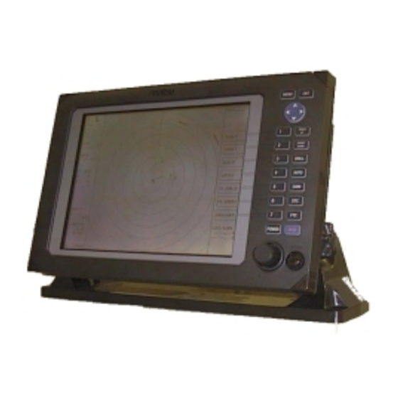
- Page 1 RA40C/RA41C/RA42C Marine Radar Instruction Manual 1st Edition • Read this manual before using the equipment.
-
Page 2: Table Of Contents
Index Adjustment Off-center (OFF-C) ......39,54 Distance ....... 75 Option..........87 Angle........75 Tuning ......... 76 Antenna height ..... 77 Parallel cursor (///CSR)....38,49 Automatic gain...... 78 PPI Screen........62 Automatic STC...... 78 PPI/NAV Screen ......64 ALL PPI Screen ......64 PPI/PPI Screen .......63 ALL PPI/PPI Screen ...... - Page 3 This indicates the ground (earth) terminal. If the equipment cannot be grounded via the power cord, connect this terminal to ground. There is a risk of serious electric shock if the equipment is not grounded. RA40C/RA41C/RA42C Marine Radar Instruction Manual 21st Jul.
-
Page 4: Distance
For Safety • • WARNING • • •DO NOT OPEN T HE COVER EXCEPT SERVICE • •••••••••••••••••••••• ••••••••••••• PERSONNEL. YOU MAY GET AN ELECTRIC SHOCK. • •••••••••••••••••••••••• •SWITCH OFF SHIPS MAIN AND PULL OFF MOTOR •••••••• FUSE BEFORE MAINTENANCE. ••••••••••••••••••••••••• ROTATING ANTENNA MAY HIT YOU. - Page 5 • WARNING • • • SEE INSTRUCT ION MANUALS BEFORE • ••••••••••••• •••••••••••• • CONNECTING POWER. •••••••••••••• SAFETY INFORMATION IS WRITTEN IN. • •••••••••••••• • EARTH CONNECTION ESSENTIAL ••••••••• BEFORE CONNECT ING POWER. • •••••••••••• YOU MAY GET AN ELECTRIC SHOCK. •...
- Page 6 Installation Radio laws dictate that this radar may only be installed by properly licensed personnel. Licensing You must obtain a license as prescribed by the Radio Law to operate this unit. To Customers * To use this equipment effectively, the operation and maintenance procedure in this manual must be followed properly.
- Page 7 3.4 Installing Scanner Unit ................14 3.5 Installing Antenna Unit ................15 3.6 Installing Display Unit................. 16 3.7 Connecting Cables..................17 3.7.0 Interconnecting cable (RA40C Radome scanner)..........17 3.7.1 Interconnecting cable (RA41C Radome scanner) ........17 3.7.2 Interconnecting cable (RA42C Open scanner) ........20 3.7.3 Grounding wire..................
-
Page 8: Angle
5.3.1 Powering On and Off................30 5.3.2 Transmitting ...................30 5.3.3 Adjusting brilliance of screen and key-backlight........31 5.3.4 Changing Distance Range (RANGE UP, RANGE DOWN) .......31 5.3.5 Automatic adjustment (AUTO) ...............31 5.3.6 Sensitivity adjustment (GAIN) ..............32 5.3.7 Removing sea clutter (STC)..............32 5.3.8 Removing rain and snow clutter (FTC)........... -
Page 9: Tuning
5.5.2 Nav (Navigation) Menu ................52 5.5.2.1 Changing display mode (MODE)............52 5.5.2.2 Guard Zone (GZ) ................53 5.5.2.3 Shifting display in specific direction (OFF-C) ........54 5.5.2.4 Setting of the SLEEP function(SLEEP) ..........54 5.5.3 Echo Menu....................56 5.5.3.1 Sensibility adjustment (GAIN) ............56 5.5.3.2 Removing sea clutter (STC) .............. - Page 10 7. RA40C OUTLINE DRAWING SCANNER UNIT 8. RA41C OUTLINE DRAWING SCANNER UNIT 9. RA42C OUTLINE DRAWING SCANNER UNIT 10. FLUSH MOUNT PROCEDURE 11. INDEX RA40C TEMPLATE OF SCANNER MOUNTING HOLES (ACTUAL SIZE) RA41C TEMPLATE OF SCANNER MOUNTING HOLES (ACTUAL SIZE)
-
Page 11: Chapter 1 Overview
1.1 Introduction The RA40C/41C/42C represents a compact, high-performance color marine radar that delivers a peak power output of 2 kW(RA40C) or 4 kW(RA41C/42C) from the an- tenna and uses an 10-inch color liquid crystal display. In addition to a microcomputer, it incorporates a video signal processing LSI and a newly developed LSI chip exclusively designed for radars, thus providing versatile func- tionality and high performance. -
Page 12: Chapter 2 Using Radar For The First Time
CHAPTER 2. USING RADAR FOR THE FIRST TIME This chapter describes basic information on radars and explains technical terms used in radar operation for those who is using a radar for the first time. 2.1 What is a radar ? A marine radar is one of the navigation equipment installed on a ship. -
Page 13: Characteristics Of Radar Wave
Beam width A beam width is defined as the width of the main lobe at an angle where the radi- ated power is halved as measured from the position from which the strongest radio wave is radiated. 2.2 Characteristics of Radar Wave Radio waves from the radar propagate while bending slightly along the terrestrial sur- face. - Page 14 case, some objects produce a complete shadow and some produce a partial shadow. In an extreme case, the shadow of an object may extend to a position far away and can- not be displayed on the screen at all. Since these shadows can be discovered when in- stalling an antenna, the problem can be avoided by changing the place of antenna in- stallation to minimize the shadow.
- Page 15 Real echo Multiple echoes Fig.2-6 False echoes of radar (Multiple echoes) False echoes caused by side lobe The radiant beam emitted from an antenna contains side lobes in directions other than that of the main beam. Since the side lobe level is low, it in no way affects distant targets.
-
Page 16: Terms Specific To Radars
This interference appears in various ways. In most cases, how- ever, it appears as spiral or radial patterns. The RA40C/41C/42C radar has a function to elimi- nate interference. Use of this function helps you minimize interference. - Page 17 Display modes This refers to a radar's display modes. There are four display modes depending on the direction in which the top of the screen faces with respect to the ship. Ship's locus (not displayed on screen) Ship's Scheduled Heading North course North...
- Page 18 VRM (Variable Range Marker) This is a circular-shaped marker whose size can be changed as desired. You can use this marker when you want to examine the distance of an echo from your ship. When measuring the distance of an echo from your ship, be sure to measure at a point close to the center of the echo image on the screen.
- Page 19 STC (Sensitivity Time Control) Since echo signals received by the radar are strong when they are coming from a short distance, it is difficult to compare signal strength between each reflected signal. To over- come this difficulty, signal strength is adjusted in such a way that the received signal levels coming from a short distance are lowered and those from a long distance are raised.
-
Page 20: Chapter 3 Installation
CHAPTER 3. INSTALLATION This chapter describes procedures for installing the RA40C/41C/42C radar in your ship and precautions to be observed during installation. Follow the procedure below to in- stall the radar. Checking contents of your package Checking power supply voltage... -
Page 21: Fuse Replacement
3.2.2 Fuse Replacement For the RA40C/41C/42C radar to be operated safely, proper rating fuses must be used. Tab.3.3 and Tab.3.4 are fuse rating tables for RA40C/41C and RA42C. Check them and replace to the fuse in the package. Tab.3-3 Supply Voltage to Fuse Table for RA40C/41C... -
Page 22: Scanner Unit
Keep the distance from the scanner to the display unit within the standard cable length of 10 m. If you use longer cable for unavoidable reasons, limit the cable length to a maximum of 30 m for RA40C and 100 m for RA41C/42C. 3.3.2 Display unit The display unit can be installed on desktop, wall surface, or ceiling. -
Page 23: Shifting Away From Obstacles
(a) A place where you can see the ship's bow when you raise your face from the radar screen. (b) A place where there is no direct sun-light to avoid display temperature up. (c) A place where there is good ventilation and minimum vibration. (d) A place where the display unit is apart more than the minimum safe dis- tance from a magnet compass as listed in Tab.3-5 below. - Page 24 Horizontal line θ Line of sight Fig.3-2 Obtaining sufficient dip angle...
-
Page 25: Installing Scanner Unit
3.4 Installing Scanner Unit When you have decided the place of installation, install the scanner unit. If a mount base like the one shown below is available, it may be easier to install the scanner. If such a mount base is not available in your ship, you may install the scanner directly to the roof, etc. -
Page 26: Installing Antenna Unit
Fig.3-5 Fixing Scanner Unit (0.47 in.) (5.51 in.) (2.36 in.) Center (5.51 in.) (1.18in.) For air tube •••••• RA40C • Radome scanner Tab.3-6 Bolts for Mounting Scanner Unit Thickness of Bolts necessary to Material Remarks mount base fix radome scanner 1-4mm(0.04-0.16 in.) -
Page 27: Installing Display Unit
Remove the protective cap covering the rotary coupler on the top of the scanner. Match the antenna radiation direction to direction of the arrow markings on the rotation base and fix the antenna in position using the four M8 accessory bolts. Arrow Antenna radiation surface 3.6 Installing Display Unit... - Page 28 WARNING Avoid a display from operating under direct sun- light. It becomes high temperature at inside of dis- play and display may be broken.
-
Page 29: Connecting Cables
Lay cable along the ship's hull or wall surface and attach it in place at intervals of about 40 cm. 3.7.0 Interconnecting cable (RA40C Radome scanner) (See Fig.3-8-1) ! Ensure that the radar is off. Connect the cable to the receptacle labeled "SCANNER"... - Page 30 $ Remove the shield cover located on the astern side. (There are four fixing screws.) % Remove the cable clamping plate and rubber ring, pass cable through the introduc- tion opening, put the rubber ring from both ends of it, and clamp the cable to the scanner unit with screws via the fixing plate.
- Page 31 Antenna Stern side Shield cover Cable shield Fixing plate Fix connector on Radome (bottom) Rubber ring PCB(X1) Interconnecting cable Inner shield X1 (Connect here) Radome (bottom) Fig.3-8-1 Fitting interconnecting cable (RA40C)
- Page 32 Antenna Stern side Shield cover Cable shield Fixing plate Fix connector on Radome (bottom) Rubber ring PCB(X11, X12) Interconnecting cable Inner shield X11 (Connect here) X12 (Connect here) Radome (bottom) Fig.3-8-2 Fitting interconnecting cable (RA41C)
- Page 33 3.7.2 Interconnecting cable (RA42C Open scanner) (See Fig.3-9) ! Ensure that the radar is off. Connect the cable to the receptacle labeled "SCANNER" on the rear panel of the display unit. " Use a T-wrench to remove the back covers of scanner unit. # Remove the two bolts securing the transceiver;...
- Page 34 TR unit fixing bolts Remove connector Fixing bolt Clumper Fixing plate Inter-connection cable Fixing bolt Cable shield terminal 5-10 mm Washer Fixing plate Scanner unit Rubber Inter-connection cable Cable inlet Fig.3-9 Fitting interconnecting cable...
-
Page 35: Scanner
3.7.3 Grounding wire WARNING Connect grounding wire before connecting power supply cable. Leakage current is too high. Connect grounding wire from the grounding terminal on the rear panel of the display unit to the ship's hull as shown below. Grounding wire SCANNER POWER OPTION... -
Page 36: Power Supply Cable
3.7.4 Power supply cable Power is fed through a knife switch ( or circuit breaker) and protective fuses, as shown in below. Main switch panel WARNING: Do not apply over 41.6V to Radar (Knife Switch with or Radar may be broken. F ses) Storage Radar Display... -
Page 37: Connecting External Equipment To Display Unit
Fig.3-13 Connecting external equipment to display unit 3.10 Countermeasure for Electromagnetic Interference RA40C/41C/42C radar provides shields in the units and the inter-unit connection ca- ble. When the radar, however, is closely installed to radio equipment such as VHF trans- ceiver, UHF transceiver, etc., or the radar and/or radio equipment are not sufficiently grounded to the hull or ship's earth, the radar may happen to cause EMI trouble. -
Page 38: When Discarding Your Radar
3.11 When Discarding Your Radar When discarding your RA40C/41C/42C radar, consult the distributor to get informa- tion on precautions to be followed. Tab.3-7 below lists the primary component materials of the RA40C/41C/42C radar for your reference. -
Page 39: Chapter 5 Operation
CHAPTER 5. OPERATION Basic operation of radar The RA40C/41C/42C radar has several fixed-function keys on the front panel. These functions can be controlled by simply pressing the key. Also, special functions can be customized to soft-keys by user-setting. The followings explain the operation of each keys. -
Page 40: Powering On And Off
5.3 Basic Operations xxx = keys to press 5.3.1 Powering On and Off Press "POWER"key to power on. POWER POWER ON 2 minutes timer and "RADAR OFF" are displayed. Keep pressing "POWER" key to power off. Press the "BRIL" key. SCREEN Control bar is indicated on the screen. -
Page 41: Adjusting Brilliance Of Screen And Key-Backlight
BRI LLI AM CE KEY BACKLI GNT 4 5.3.4 Changing Distance Range (RANGE UP, RANGE DOWN) Pressing "RANGE UP" key produces a long-distance range, and "RANGE DOWN" key a short-distance range. •• RADOME SCANNER (RA40C) RANGE 0.125 •0.25 0.75 Number of rings Range ring 0.062... -
Page 42: Sensitivity Adjustment (Gain)
controls return to manual state. AT1 Use when find navigation way in much echo such as port area, narrow channel, small islands area. The control condition is similar to slightly down GAIN. AT2 Use at open sea to suppress the sea clutter. The control condition is similar to high GAIN. -
Page 43: Removing Rain And Snow Clutter (Ftc)
(1) When the "STC" key is pressed, the STC display on the left side of the screen will be reversed as S 35 and the adjustable state will be entered. (2) When the control knob is turned, the figure will be shifted within a range of 0 and 99, and the STC can be manually adjusted. -
Page 44: Man Over Board (Mob)
5.3.9 Man Over Board (MOB) Pressing the MOB key will send the own ship's position data to the external equipment through NMEA port with "WPL" format. There is no change on the screen. To check the MOB position data, select "MOB" from the "WINDOW" menu in the "SETUP". The position of MOB and current position will be displayed on the screen. -
Page 45: Functions Of Soft Keys
5.4 Functions of Soft Keys xxx •keys to press •Outline of soft keys Any function can be optionally allocated to the key upon which numbers 1-7 are indicated. A maximum of 4 groups of functions can be allocated to each soft key, and switching between those functions is conducted by the "NEXT"... -
Page 46: Distance Measurement (Vrm2)
VRM1 → Control knob → VRM1 VRM1 is displayed and the process is finished. µθ> Other function key VRM1 is displayed and the function is shifted. µθ> VRM1 VRM1 is turned off.(b) (b) To turn off the VRM1 When the "VRM1" key is pressed twice, VRM1 disappears. (VRM1 OFF) Note: Refer to "5.5.1.2 Determining the distance (VRM1)". -
Page 47: Changing The Group Of Soft Keys(Next)
(1) Press "FL VRM2" key. “SET START POINT” is displayed and a small cross mark appears. FL VRM2 → FL VRM2 is turned ON and (Select FL VRM2) the small cross mark appears. (2) Use the left-right and up-down cursor keys to place the small cross mark on one of the two echoes whose angle will be measured, and press the "ENT"... - Page 48 The function can be changed at the "KEY ASSIGNMENT" function in the "CUSTOM" menu of the "SETUP".
-
Page 49: Erasing Heading Maker Temporarily (Hdg Off)
5.4.8 Erasing heading maker temporarily (HDG OFF) Press the “HDG OFF” key. The heading marker is not displayed as long as you hold it down. 5.4.9 Using parallel cursors (///CSR) Press the “///CSR” key. Parallel cursors will appear on the screen. As you move EBL, the parallel cursors also move. -
Page 50: Off Center (Off-C)
A function that sets a guard zone of any distance and any angle range, creating alarm tone when either echoes above a certain level exist (IN MODE) or no echoes exist(OUT MODE). When GZ is operated with soft keys, guard zone settings and ON/OFF settings can be conducted, but the mode (IN or OUT) is to be set in the menu. -
Page 51: Setting Of The Sleep Function(Sleep)
→ Up/Down & Left/Right → ENT ---------------- Conduct Off Center to exit the adjustment state. OFF-C Note: VRM2 and EBL2 do not follow the OFF-C function while floating. The function operates on PPI screen only. (b) To cancel the setting OFF-C ---------------------------------------------------The "OFF-C"... -
Page 52: Echo Expansion (St)
99, and the receiver tuning can be manually adjusted. (3) After the adjustment is finished, press the "ENT" key to exit from the adjustment state. If some other function key is pressed, shift to that function will take place. → Control knob →... -
Page 53: Increasing Sensitivity (S/L)
the "ENT" key and the setting is completed. The area around the cross cursor is displayed in 2x magnification, with blinking "ZOOM" displayed at the screen upper right, indicating that a ZOOM display is being conducted. To cancel the ZOOM function, press the "ZOOM" key again or change the range scale. Note: Refer to "5.5.3.7 Enlarging selected areas (ZOOM)". -
Page 54: Changing The Color Of Screen (Picture)
µθ> → or (Select left screen) Left screen activated If VRM1 is controlled on the screen that is oposit from current VRM1 displayed screen, VRM1 is moved and displayed to activated screen. The EBL1, EBL2, and VRM2 is the same manner. -
Page 55: Change To Ppi/Nav Screen (Ppi/Nav)
Press the "PPI/PPI" key, the screen will change to HU S PPI/PPI screen. Use to change the screen from other modes to PPI/PPI. Note: (1) The radar picture is refreshed with two scanning interval for each screen. Right screen picture is 55/35 35/AT holded during refreshing left screen, left screen... - Page 56 Press the "ALL PPI2" key, the screen will change to .25 . @ . 25 HU S ALL PPI/PPI screen. Use to change the screen from other modes to ALL PPI/PPI. Note: (1) The range, rings interval, display mode are displayed on the upper left of each screen.
-
Page 57: Nav (Navigation) Menu
5.5.2 Nav (Navigation) Menu xxx = keys to press Radar functions for navigation aid are in this menu. •Common operations for the NAV menu (Up to the point when "NAV" menu is selected from the main menu) Press the "MENU" key and select "NAV" from the displayed 4 main menus using the left-right cursor. - Page 58 5.5.2.2 Guard Zone (GZ) A function that sets a guard zone of any distance and any angle range, creating alarm tone when either echoes above a certain level exist (IN MODE) or no echoes exist(OUT MODE). Setting guard zone (1) Select GZ from the pull-down display items using the up-down cursor keys, and press the “ENT”...
-
Page 59: Shifting Display In Specific Direction (Off-C)
Stop the alarm tone When the alarm sounds, press any key to stop. But the guard zone function is still working, the alarm may sounds again. To "OFF" the guard zone function, select "OFF" from GZ menu. Note1: To switch the IN or OUT mode, refer to “Guard Zone Mode” in section 5.5.4.5.3 “Changing the content of settings 2 (PRESET2)”... - Page 60 state) and the LCD backlight turned off. This action is repeatedly executed. Usage example, set a guard zone and have the warning signal automatically confirmed every prefixed period. (1) Use the up-down cursor keys to select SLEEP from among the pull-down display items, and press the "ENT"...
- Page 61 b) If a key is pressed while the 2-minute timer is in use, or during transmission , the SLEEP function is canceled.
-
Page 62: Echo Menu
5.5.3 Echo Menu xxx •••keys to press Adjustment options to be conducted on the echoes displayed on the screen •Common operations for the ECHO menu (Up to the point when "ECHO" menu is selected from the main menu) Press the "MENU" key and select "ECHO" from the displayed 4 main menus using the left- right cursor. -
Page 63: Removing Sea Clutter (Stc)
Up/Down --> --> Up/Down (Select GAIN) |->(Select MANU) --------------------> Control knob --> ENT Set to MANU mode (GAIN adjustment) |->(Select AUTO) ----------------------------------- --> ENT Set to AUTO mode 5.5.3.2 Removing sea clutter (STC) Refer to the section, “Sensibility adjustment (GAIN)”. Up/Down -->... -
Page 64: Echo Expansion (St)
Indicated setting value manual mode, 5.5.3.5 Echo expansion (ST) Expanding the echo to the direction of the distance. Two types of echo expansion exist, select ST1 or ST2 from the menu. (1) Use the up-down cursor keys to select ST from among the pull-down display items, and press the "ENT"... -
Page 65: Enlarging Selected Areas (Zoom)
Note: When PPI+PPI or ALL PPI+PPI screen mode is used, TRACK function can be used only on CONT mode. locus of target real echo moving direction TK 15SEC disappear after selecting time the length of the track up/down --> --> up/down ... -
Page 66: Increasing Sensitivity (S/L)
Up/Down --> ENT --> Up/Down (Select ON) --> ENT --> Up/Down & Left/Right --> ENT ZOOM Setting (Select ZOOM) (Move cross cursor) |--> (Select OFF) --> ENT ---------------- ZOOM canceled Note 1) VRM2 and EBL2 do not follow the ZOOM function during a floating state. Note 2) Normal screen returns when you change the range scale. -
Page 67: Buzzer
5.5.4.5.2 Changing the content of settings 1(PRESET1) (1) When PRESET1 is selected from CUSTOM items and the "ENT" key is pressed, the PRESET1 screen (See chart below) appears. Select items with up-down keys contents with left-right keys. The selected items will be enclosed by square frames and the contents will appear in reversed display. - Page 68 • 0 SHORT LONG P TABLE 2 SHORT LONG Note• RA40C Pulse width 0 : 0.12 uS, 1 : 0.3 uS, 2 : 0.8 uS ΡΑ41Χ/42Χ Πυλσε ωιδτη 0 : 0.08 uS, 1 : 0.25 uS, 2 : 0.8 uS...
- Page 70 5.5.4.5.3 Changing the content of settings 2 (PRESET2) Refer to the section, “Changing the content of setting 1(PRESET1)”. PRESET2 a) Guard Zone Level b) Guard Zone Mode GZ LVL c) Hold GZ MODE d) Display Unit Mode HOLD e) External Buzzer DISPLAY MONI NAVI...
- Page 71 j) Ship's Speed Own ship's speed setting NMEA: Data input from NMEA port MANU: ship's speed with manual Set the Speed with control knob. k) Indication Language Select the language for MENU and SOFT KEY( Note2: ) l) Scan Speed Scanning speed setting STD: Standard HIGH: High speed...
- Page 72 5.5.4.5 Changing the content of the setting (CUSTOM) Note) Items in CUSTOM are for conducting settings and adjustments at the time of installation, which need not be conducted normally. -Common operations for CUSTOM Use the up-down cursor keys to select CUSTOM after ”the common operations for the SETUP” menu, and press either the "ENT"...
- Page 73 5.5.4.5.1 Changing the settings of soft keys (KEY ASSIGN) Conducting alterations and new settings for the functions of keys with number displays of 1-7. (1) Screen display for the setting When KEY ASSIGN has been selected with the up-down cursor keys from among the CUSTOM items and the "ENT"...
- Page 74 than 1 key) are possible.) When settings are to be conducted for more than 1 key, repeat the operations (3)-1 to (3)-2. (Example 3) (4) Completing the setting After the setting has been finished, press the ENT key to exit from KEY ASSIGNMENT. Example of an operation (The process up to the selection of KEY ASSIGNMENT from the SETUP menu is omitted.
- Page 75 5.5.4.5 Changing the content of the setting (CUSTOM) Note) Items in CUSTOM are for conducting settings and adjustments at the time of installation, which need not be conducted normally. -Common operations for CUSTOM Use the up-down cursor keys to select CUSTOM after ”the common operations for the SETUP” menu, and press either the "ENT"...
- Page 76 5.5.4.5.1 Changing the settings of soft keys (KEY ASSIGN) Conducting alterations and new settings for the functions of keys with number displays of 1-7. (1) Screen display for the setting When KEY ASSIGN has been selected with the up-down cursor keys from among the CUSTOM items and the "ENT"...
- Page 77 than 1 key) are possible.) When settings are to be conducted for more than 1 key, repeat the operations (3)-1 to (3)-2. (Example 3) (4) Completing the setting After the setting has been finished, press the ENT key to exit from KEY ASSIGNMENT. Example of an operation (The process up to the selection of KEY ASSIGNMENT from the SETUP menu is omitted.
-
Page 78: Setup Menu
5.5.4 SETUP Menu To be used for various settings and switching of the screen •Common operations for the SETUP menu (Up to the point when "SETUP" menu is selected from the main menu) Press the "MENU" key and select "SETUP" from the displayed 4 main menus using the left- right cursor. -
Page 79: Limitation Of Screen Operation
→ → → (Select PPI• → Up/Down Up/Down ENT •a• → •select WINDOW• (Select PPI+SEMI3D• → •b• → (Select PPI+PPI• → ENT •c• → (Select PPI+NAV• → ENT •d• → (Select ALL PPI• → ENT •e• → (Select ALL PPI+PPI• →... -
Page 80: (A) Ppi Screen
(a) PPI Screen D ‚ V ‚ T D ‚ Q ‚ T ‚ g ‚ t All functions can be used on this screen. PPI Scr een... -
Page 81: (B) Ppi/Semi3D Screen
(b) PPI/SEMI3D Screen It becomes simultaneous control at the time as D ‚ V ‚ T D ‚ Q ‚ T ‚ g ‚ t ‚ r two screen. Note: All controls, such as EBLs, VRMs effects both screen. The ZOOM, OFF-C, FL EBL2, and FL VRM2 could not be used on this mode. -
Page 82: (D) Ppi/Nav Screen
b) Adjusting GAIN of LEFT screen. 1) When the RIGHT range indicator displayed in reverse, change to LEFT screen with "SEL WIN" function. 2) Press the "GAIN" key, "G50" will displayed in reverse and ready for adjusting GAIN. 3) Adjust GAIN with the control knob. Adjust STC and FTC in a same manner as GAIN. -
Page 83: (F) All Ppi/Ppi Screen
(f) ALL PPI/PPI Screen D ‚ V ‚ T D ‚ Q ‚ T D ‚ Q ‚ T ‚ g ‚ t ‚ r D ‚ P ‚ Q ‚ T Note1: The RANGE, RINGS interval, and Display mode are displayed on the top of the screen. - Page 84 5.5.4.3 Changing the color of screen (PICTURE) Changing the color of screen depending on weather and day / night environment conditions will be effective for easy viewing . When "PICTURE" is selected with the up-down cursor keys from among the pull- down display items, select "DAY"...
- Page 85 SYSTEM CHECK MENU MEMORY CHECK a) ROM --------------------------------------- > ROM b) RAM ---------------------------------------- > RAM c) Backup memory ----------------------- > BACKUP Indicates the cursor status . SIGNAL CHECK RNG U d) Transmit trigger ----------------------- > (1) TRIGGER e) Bearing pulse -------------------------- >...
-
Page 86: Menu Operation
5.5 MENU Operation List of MENU List of Main Menu MARK ECHO SETUP (MAIN-MENU) (MAIN-MENU) (MAIN-MENU) (MAIN-MENU) EBL1 ON/OFF MODE HU/HS/NU/CU/TM GAIN AUTO/MAN WINDOW PPI/SEMI3D+PPI/ PPI+PPI/PPI+NAV/ •MANU/NMEA• VRM1 ON/OFF AUTO/MAN/HARBOR ALLPPI/ALL PPI+PPI/MOB EBL2 ON/OFF ON/OFF AUTO/MAN VRM2 ON/OFF OFF-C ON/OFF TUNE AUTO/MAN SEL WIN... - Page 87 5.5.1 Mark Menu •keys to press Setting for markers and cursors • Common operations for the MARK menu (Up to the point when "MARK" menu is selected from the main menu) Press the "MENU" key and select "MARK" from the displayed 4 main menus using the left- right cursor.
- Page 88 5.5.1.2 Determining the distance (VRM1) (1) Select VRM1 from the pull-down display items using the up-down cursor key, and press either the "ENT" key. When the ON/OFF sign is displayed beside the VRM1 item, select ON with the up-down cursor keys and press the "ENT"...
- Page 89 appears. (Once this is set, the "ON" state continues unless changes are made.) Up/Down → ENT → Up/Down → ENT --------------------------------FL VRM2 is turned ON and (Select FL VRM2) (Select ON) the small cross mark appears. (b) Setting a reference point for measurement of the distance Use the left-right and up-down cursor keys to place the small cross mark on one of the two echoes whose distance will be measured, and press the "ENT"...
- Page 90 (c) Measuring Perform the operations in the above mentioned "Common operation for the MARK menu" and "measuring the distance(EBL2)", and place the EBL2 on another echo. EBL2 is displayed on the screen based on the placed fixed cross cursor. " 2 xx.
- Page 91 Up/Down (Select ON) ENT ----------------- Range rings appears µ> → (Select RINGS) Up/Down (Select OFF) ENT ----------- Range rings non-appears •Number of range rings and range interval Radome antenna (RA40C) • Range 0.125 •0.25 0.75 Number of Rings Interval 0.062 0.125...
-
Page 92: Cross Cursor (+)
items, and press the "ENT" key. (2) When ON is selected with the up-down cursor key from the ON/OFF display beside the VAR RNG item, and the "ENT" key is pressed, the VAR RNG function becomes valid and will be displayed at the upper left of the screen (beside MODE). Setting procedure →... - Page 94 CHAPTER 4. FUNCTIONS AND NAMES Function and name of each part The RA40C/41C/42C radar consists of a display unit to display video images on a screen and a scanner unit configured with an antenna to radiate radio waves and other components.
- Page 95 4.2 Rear panel SCANNER POWER OPTION Power supply connector " Grounding terminal Scanner connector Option connector ! ! ! ! Power supply connector Use this connector to plug in the power supply cable. Standard NMEA interface terminal is included in this connector. Refer to Section 3.7 “ Connecting Cables “ and Section 3.9 “Connecting External Equipment to Display Unit “.
- Page 96 4.4 Radar screen (Dual screen) ex) PPI/PPI screen Range(Left screen) Range(Right screen) Range ring interval Range ring interval (Left screen) (Right screen) Tune meter 1.0_ HU Picture hold HOLD EBL1 Display mode VRM1 Pulse width EBL2 VRM2 Indicate soft key Cross cursor FL EBL2 FL VRM2...
- Page 97 4.6 Radar screen (All PPI /PPI screen) Range(Left screen) Range(Right screen) Range ring interval Range ring interval (Left screen) (Right screen) Picture hold 0_ HU .2 5 HO LD Display mode Gurad zone(Right screen) Guard zone(Left screen) Pulse width Cross cursor 4.7 Navigation screen N A V D I S P L A Y Way point...
- Page 98 Deviation from course Indication mark 0.00 -- >< 0.02 -- > or < >> or << 0.04 -- > Indicates starboarding the helm 0.08 -- >>> or <<< (right) 0.16 -- >>>> or <<<< < Indicates porting the helm (left) Tab.6 Indication of deviation from course...
-
Page 99: Chapter 6 Maintenance And Inspection
Check the length of brushes. If the length is brush(RA42C) under 6mm, change them to new one. *: Use grease for plastics for RA40C/41C. If you use other type of grease(not for plastics), it may break antenna Concerning Consumable The radar uses consumable as listed below that require periodic replacement. - Page 100 (3) Fuse Power supply cable The fuse is built in the power supply cable. To display unit If the fuse appears to be blown, check the fuse. If Push blown, replace following the procedure shown in Fig.6-2. Wire(White) Turn counterclockwise and pull Spring Fuse...
- Page 101 Check the length of brushes. If the length is brush(RA42C) under 6mm, change them to new one. *: Use grease for plastics for RA40C/41C. If you use other type of grease(not for plastics), it may break antenna Concerning Consumable The radar uses consumable as listed below that require periodic replacement.
- Page 102 (3) Fuse Power supply cable The fuse is built in the power supply cable. To display unit If the fuse appears to be blown, check the fuse. If Push blown, replace following the procedure shown in Fig.6-2. Wire(White) Turn counterclockwise and pull Spring Fuse...
-
Page 103: Chapter 7 Troubleshooting
For faster service, please let us know about followings when you request repair: (1) Ship's name, place of anchorage, allowable repair period or time (2) Radar type (This radar is RA40C, RA41C or RA42C.) (3) Manufacturing number (indicated on the back of the display unit) - Page 104 When you have finished self-check, inspect each part of the radar according to Tab.7-1. Tab. 7-1 Troubleshooting Symptom Cause Corrective action (1) Radar cannot be powered Power cable is disconnected. Connect power cable correctly. Power supply voltage is off Use Specified power supply. specified value (See Section 3.2) Fuse in power cable is blown.
-
Page 105: Chapter 8 Product Specifications
Power supply voltage and power consumption ••••Power supply voltage: 24Vdc (nominal) (10.2 to 41.6 Vdc) ••••Power consumption: 55 W or less (RA40C/41C) 70 W or less (RA42C) Distance range: 0.125 to 24 NM, 9 ranges (RA40C) 0.125 to 36 NM, 10 ranges (RA41C) 0.125 to 48 NM, 10 ranges... - Page 106 Wind resistance: 100 knots (max.) Waterproof standard: (D/U): IPX-5 (S/U): IPX-6 Interconnecting cable: 30 m in max. (RA40C) 100 m in max. (RA41C/42C) Noise: (D/U): 65 dB or less (S/U): 65 dB or less (RA40C/41C) (S/U): 70 dB or less (RA42C)
-
Page 107: Scanner Unit
4 (-50% to +20% ) 2.0 (±50% ) 0.8 ± 0.1 4 (-50% to +20% ) 2.0 (±50% ) P0N, 9445 ± 30 MHz (RA40C) Radio wave type and frequency: P0N, 9410 ± 30 MHz (RA41C/42C) 24 rpm ± 20%... -
Page 108: Language
Cursor Control: Analog cursor key and rotary encoder VRM: 2 lines (One line can be offset.) Unit of distance can be selected from NM, KM, and EBL: 2 lines (One line can be offset.) Display modes: HU, HS, NU, CU, and TM Off-center: Can be 100% off-centered over the full range. -
Page 109: Option
4 sets (for RA40C/41C) M12 hexagonal bolt 4 sets (for RA42C) 8.6 Options Interconnecting cable (15, 20, and 30 m for RA40C) Interconnecting cable (15, 20, and 25 m for RA41C/42C) Flush-mount installation kit Junction box for external connection (with cable 1.5m) - Page 110 0 to 5V positive pulse, rising edge GYRCK+ Gyro Interface clock(+) input GYRCK- Gyro Interface clock(-) input apply 5V pulse between (+) and (-), isolated GYRDT+ Gyro Interface data(+) input GYRDT- Gyro Interface data(-) input apply 5V pulse between (+) and (-), isolated MARK_I External Marker signal input, ex) Radar Buoy negative video, 0 to -1V Zi = 50ohm...
Need help?
Do you have a question about the RA40C and is the answer not in the manual?
Questions and answers