Table of Contents
Advertisement
Quick Links
Advertisement
Table of Contents

Related Manuals for Koden MDC-7060


Summary of Contents for Koden MDC-7060
-
Page 3: Document Revision History
No part of this publication may be reproduced, transmitted, translated in any from by any means without the written permission of Koden Electronics Co., Ltd. The technical descriptions contained in this publication are subject to change without notice. Koden assumes no responsibility for any errors, incidentals or consequential damages caused by misinterpretation of the descriptions contained in this publication. -
Page 4: Important Notice
Koden is not liable for damages of accompaniment (change/loss of memorized content, loss of business profit, stop of business) arisen from use or failure of our products. If the stored data are changed or lost, irrespective of causes of troubles and damages, Koden is not liable for them. ... -
Page 5: For Your Safe Operation
MDC-7000/7900 Series For Your Safe Operation For Your Safe Operation Symbols used in this Operation Manual This manual uses the following symbols. Understand the meaning of each symbol and implement the maintenance and inspection. Symbol Meaning Warning Symbol This symbol denotes that there is a risk of death or serious injury when not dealt with it correctly. - Page 6 For Your Safe Operation MDC-7000/7900 Series Caution related to Equipment Caution, high voltage inside. High voltage that may cause severe injury or death is present. High voltage remains in circuit even after power is turned off. High voltage circuit has a protective cover with a warning label. Make sure to turn off power and discharge capacitors before working on the system.
- Page 7 Specified power density and distance from the radar (in accordance with the provision as specified in IEC 60945) Model name Transmission power / 100W/m 50W/m 10W/m Antenna length MDC-7060 6kW / 4 feet Antenna 1.5 m 2.1 m 4.5 m MDC-7960 6kW / 6 feet Antenna 1.7 m 2.4 m...
- Page 8 For Your Safe Operation MDC-7000/7900 Series Do not disassemble or modify. It may lead to trouble, fire, smoking or electric shock. In case of trouble, contact our dealer or our company. In case of smoke or fire, switch off the power in the boat and the power of equipment.
-
Page 9: Break In Procedure Of Stored Radar
MDC-7000/7900 Series Break in procedure of stored radar Break in procedure of stored radar Following procedure is recommended for “Break In” of the stored radar. Otherwise the radar sometimes exhibits unstable transmitting operation such as arcing at its initial operation after long period of storage and make the operation more difficult. -
Page 10: Used Battery And Radar Disposal
Used battery and radar disposal MDC-7000/7900 Series Used battery and radar disposal A high-energy density lithium ion battery is installed in this radar. Improper disposal of a lithium ion battery is discouraged as the battery has a possibility of short-circuiting. If it gets wet, the generation of heat, explosion or ignition may occur resulting in an injury or fire. -
Page 11: In Case No Heading And Speed Signals Are Input From Navigation Equipment
MDC-7000/7900 Series In case no Heading and Speed signals In case no Heading and Speed signals are input from navigation equipment When no Heading and Speed signals are input from navigation equipment (in case not connected), this radar gives alarms and warning messages at lower right of the display, if the radar is started up factory default settings. -
Page 12: Table Of Contents
Contents MDC-7000/7900 Series Contents Document Revision History ......................i Important Notice ........................ii For Your Safe Operation ......................iii Break in procedure of stored radar ..................vii Used battery and radar disposal .................... viii In case no Heading and Speed signals are input from navigation equipment ......ix Contents ........................... - Page 13 MDC-7000/7900 Series Contents Transmission ON ...................... 2-3 Transmission OFF ....................2-3 Tuning method ......................2-4 Change MAN (manual) and AUTO................2-4 Optimized value setup method ................2-4 Change range scale ....................2-5 Change range unit (NM / km / sm / kf / ky) .............. 2-5 Adjust receiver gain (GAIN) ..................
-
Page 14: Contents
Contents MDC-7000/7900 Series 2.16 Measurement distance/bearing by ERBL ..............2-30 Change ERBL mark to LINE or RING ..............2-31 Change ERBL offset method .................. 2-31 2.17 Change color and brightness (Day/Night) ............... 2-32 Setup color ......................2-32 Setup USER1 and USER2 color ................2-33 Setup brightness ..................... - Page 15 MDC-7000/7900 Series Contents 2.36.5 BIRD VIEW ....................2-56 Chapter 3 Alarm ...................... 3-1 Collision avoidance ....................3-1 Echo alarm ........................ 3-1 How to set echo alarm area (Fan type) ..............3-1 Map area alarm ......................3-3 How to edit map area ....................3-3 How to move map area ....................
- Page 16 Contents MDC-7000/7900 Series Ship outline ......................4-10 HDG line ......................... 4-10 Turn indicator ......................4-11 OS display ......................4-11 OS MMSI ........................ 4-11 Message display ..................... 4-11 AIS filter ........................4-12 AIS alarm [Sleeping lost] ..................4-13 AIS auto ACQ ......................4-13 Types of AIS target symbol ..................
- Page 17 MDC-7000/7900 Series Contents EVENT MKR ......................6-11 AREA ........................6-12 MONITORED ROUTE .................... 6-12 6.10 WPT ID DISP ......................6-13 6.11 TARGET TRACK ID ....................6-13 6.12 DATUM ........................6-13 6.13 EDIT USER DATUM ....................6-14 6.14 POSITION OFFSET ....................6-14 POSITION MANUAL OFFSET ................
- Page 18 Contents MDC-7000/7900 Series Version confirmation ....................7-9 How to update the system program ................. 7-9 Chapter 8 Principal of radar system ................. 8-1 What is radar system?....................8-1 Side lobe ........................8-1 Beam width ....................... 8-2 Characteristics of radar radio wave ................8-2 Target hardness reflected ..................
- Page 19 MDC-7000/7900 Series Contents 11.5.4 Serial data input/output specification (AIS) ..........11-32 11.5.5 Radar input/output signal specification ............. 11-33 11.5.6 Talker device code of the data output devices .......... 11-34 11.5.7 Priority of talker device code ..............11-34 Chapter 12 Index ....................12-1 0093169010-10 xvii...
-
Page 20: Introduction
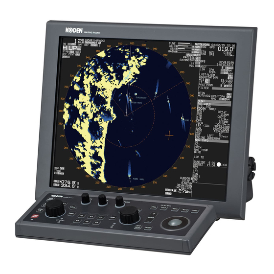
MDC-7000/7900 Series Introduction The MDC-7060/7010/7020/7960/7910/7920 type Radar system is a compact and high performance shipboard radar system consisting of the Antenna & Scanner unit with a transmit power of 6kW/12kW/25kW, a Display unit with a 19 inch color LCD (Liquid Crystal Display) and Operation unit. -
Page 21: Configuration Items
CONNECTOR.KIT Operation manual MDC-7000_7900.OC.OM.E Installation manual MDC-7000_7900.OC.IM.E Quick reference MDC-7000_7900.OC.QR.E * RW701A-04: 4feet, RW701A-06: 6feet, RW701B-09: 9feet ** RB717A: 6kW (MDC-7060), RB718A: 12kW (MDC-7010), RB719A: 25kW (MDC-7020) MDC-7960/7910/7920 Name Type Antenna Scanner Display unit MRD-108 Operation unit with connecting cable... -
Page 22: Option List
Configuration items MDC-7000/7900 Series Option list Name Type Comment Gyro Interface S2N, U/N 9028C Gyro converter Log pulse NMEA L1N, U/N 9181A 200pulse/NM only converter Rectifier unit PS-010 5A fuse attached. VL-PSG001 20A fuse attached. AC power cable VV-2D8-3M Without a connector on the both sides Junction box JB-35 With CW-376-5M... -
Page 23: Chapter 1 Display And Operation
MDC-7000/7900 Series Chapter 1 Display and Operation Chapter 1 Display and Operation 1.1 Radar Display Upper left corner Upper right corner Own ship data Heading EBL1 line Target status ERBL EBL2 (OFFSET) Target and Information area VRM1 VRM2 Assistant display Range Rings (Navigation Information) -
Page 24: Upper Right Corner
Chapter 1 Display and Operation MDC-7000/7900 Series Upper right corner Inter-switch mode PICTURE setting PROCESS setting TUNE setting EXPANSION setting GAIN setting SEA setting RAIN setting VIDEO mode setting Lower left corner Sector MUTE ON MAP function display TRAIL TIME TRAIL TRUE/REL Own Ship Past Track ON EBL1 active mark... -
Page 25: Own Ship Data
MDC-7000/7900 Series Chapter 1 Display and Operation Own ship data Date UTC/LOCAL TIME Day/Month/Year Time Heading CTW or COG STW or SOG Set and Drift Own ship position Target status Vector REL/TRUE Vector Time Limit CPA Limit TCPA AIS and TT Lost Alarm Association setting AIS ON AIS and TT Past position... -
Page 26: Target And Map Information Area
Chapter 1 Display and Operation MDC-7000/7900 Series Target and MAP information area Selected AIS, TT or MAP (COAST LINE, NAV LINE, ROUTE, EVENT MKR and AREA) information is displayed, this data can be changed by selecting with cursor and pressing ENT key. Cursor and press ENT key. -
Page 27: Assistant Display (Navigation Information)
MDC-7000/7900 Series Chapter 1 Display and Operation Assistant display (Navigation information) TGT OUTLINE TGT LIST CPA/TCPA TGT LIST BRG/RNG NAV INFO TGT LIST LAT/LON TGT LIST COG/SOG TGT LIST LABEL SELECTED AIS INFO BIRDVIEW WIDEVIEW ZOOMVIEW Selection values are NAV INFO, TGT OUTLINE, TGT LIST (CPA/TCPA), TGT LIST (BRG/RNG), TGT LIST (LAT/LON), TGT LIST (COG/SOG), TGT LIST (LABEL), SELECTED AIS INFO, BIRDVIEW, WIDEVIEW and ZOOMVIEW. -
Page 28: Alarm Display Area
Chapter 1 Display and Operation MDC-7000/7900 Series Alarm display area When a malfunction or operation error has been detected in the radar, alarm message will appear at the alarm display area. Abnormalities are categorized as [ALARM], [WARNING] and [CAUTION]. When these messages actually appear and there is something wrong with radar, record the alarm details by type, location and status and press OFF key. - Page 29 MDC-7000/7900 Series Chapter 1 Display and Operation WARNING (Displayed with yellowish orange) WARNING 9999999 15 / 10 / 14 16:23 RADAR MESSAGE In case of unacknowledged alarm, icon and WARNING of priority will be flashing, and 2 short audible signals will be repeating every 60 sec. Type of WARNING icons Active Unacknowledged warning...
-
Page 30: Alarm Display Area (Navigation Graph)
Chapter 1 Display and Operation MDC-7000/7900 Series Alarm display area (Navigation graph) Following navigation data graphs can display at alarm display area. Water temperature and water depth Wind Set/drift Course and speed Radar echo level monitor Move cursor on the alarm display area with trackball, and press ENT key. Navigation data graph will be displayed as follows. -
Page 31: Operation Unit
MDC-7000/7900 Series Chapter 1 Display and Operation 1.2 Operation Unit Key/knob name Contents POWER ON/OFF key Turn on and off the power. POWER lamp Status of power on. STBY/TX key Transmission on and off. SP/LP key Change transmission pulse width. DAY/NIGHT key Change echo color, day or night. - Page 32 Chapter 1 Display and Operation MDC-7000/7900 Series PANEL key Control panel brilliance adjustment VRM/PANEL knob Adjust VRM1,VRM2 or panel brilliance PI lamp Status lamp of parallel index lines ERBL key Electronic range and bearing line on and off OFF key Erase heading line, stop alarm sound, etc.
-
Page 33: Menu Usage
MDC-7000/7900 Series Chapter 1 Display and Operation Menu usage Turn MENU on and off Press MENU key, “Menu” display on the right side of the display. “Menu” display is turned off by pressing MENU key again. Select menu item Press MENU key and “Main menu” will show on the display. Select one of main menu items by moving the trackball up or down. -
Page 34: Cursor Access Usage
Chapter 1 Display and Operation MDC-7000/7900 Series Note: About the shaded menu: [INTER-SWITCH] in [SYSTEM] menu, and [SECTOR MUTE], [BACKUP], [TOTAL HOUR] and [TX HOUR] in [MAINTENANCE] menu are not available during transmission, therefore they are greyed out. Transmission Standby Standby Transmission Cursor Access usage... -
Page 35: Chapter 2 Radar Basic Operation
Wait for 120 sec. (*1) or 180 sec. (*2) until preheating countdown time has disappeared, and status changes from WAIT to STANDBY at the upper left of the display. (*1) MDC-7060/7960/7010/7910 (*2) MDC-7020/7920 The brilliance of the display is set to the previous value of the last power off. -
Page 36: Change Brilliance
Chapter 2 Radar Basic Operation MDC-7000/7900 Series Change Brilliance Display Brilliance Press BRILL key. The BRILL adjustment window will appear in the upper left of the display. BRILL adjustment window Turn EBL knob clockwise to increase the display brilliance. Turn EBL knob counterclockwise to decrease the display brilliance. The display brilliance can also be changed in five steps by pressing EBL knob. -
Page 37: Transmission
MDC-7000/7900 Series Chapter 2 Radar Basic Operation Transmission Transmission ON After preheating time countdown is completed, the radar can be placed in transmit mode. Press STBY/TX key, or select the STANDBY box at the upper left corner of the display using trackball and press ENT key. -
Page 38: Tuning Method
Chapter 2 Radar Basic Operation MDC-7000/7900 Series Tuning method The transmitting and receiving frequency of this radar may become detuned by environmental changes. This result in “detuning” of the gain and the same echo images may show weaker, even if the setup is the same as before. -
Page 39: Change Range Scale
Trackball operation Cursor point Model-specific ranges are as shown below. Model name MDC-7020/7920 (Max. output : 25 kW) MDC-7010/7910 (Max. output : 12 kW) MDC-7060/7960 (Max. output: 6 kW) Range(NM) 0.125 0.25 0.75 96** * 32NM and 64NM is for 6kW / 12kW only. -
Page 40: Adjust Receiver Gain (Gain)
Chapter 2 Radar Basic Operation MDC-7000/7900 Series Adjust receiver gain (GAIN) It is recommended to adjust [GAIN] in the upper right side of the display to have the evenly scattered vague background noise with low intensity in the PPI. Lower than required [GAIN] may result in missing small vessels and buoys. Higher [GAIN] than required may result in difficult discrimination between small ships and densely displayed high level background noise. -
Page 41: Man Adjustment Of Gain
MDC-7000/7900 Series Chapter 2 Radar Basic Operation MAN adjustment of GAIN When MAN GAIN is selected, GAIN can be adjusted manually. Turn GAIN knob clockwise to increase receiving gain. Turn GAIN knob counterclockwise to decrease receiving gain. Gain Down Note: •... -
Page 42: Reject Sea Clutter (Anti-Sea)
Chapter 2 Radar Basic Operation MDC-7000/7900 Series Reject sea clutter (anti-SEA) MAN (manual) SEA and AUTO (automatic) SEA are provided for anti-SEA function. On the rough sea, SEA clutter noise appears around antenna position (center spot), and short distant targets are masked and not recognizable. -
Page 43: Auto Adjustment Of Sea
MDC-7000/7900 Series Chapter 2 Radar Basic Operation AUTO adjustment of SEA When AUTO SEA is set, anti-SEA is adjusted automatically. Note: AUTO SEA may erase weak target echoes. If excessive sea clutter erasing or too much clutter is observed, turn SEA knob clockwise or counterclockwise to adjust AUTO SEA effectively. If not setup properly, adjust it by referring to 4.5.3 Setup GAIN MIN and MAX mode of Installation manual. -
Page 44: Reject Rain/Snow Clutter (Anti-Rain)
Chapter 2 Radar Basic Operation MDC-7000/7900 Series Reject rain/snow clutter (anti-RAIN) In rain or snow, targets become hard to be seen as a result of unwanted weather reflection. Rain or snow image appears as a large target echo with surrounding mid gradation rim. Anti-RAIN is available MAN and CFAR. -
Page 45: Changing Method Of Cfar And Man
MDC-7000/7900 Series Chapter 2 Radar Basic Operation Changing method of CFAR and MAN By RAIN knob When RAIN knob is pressed, MAN and CFAR change because of the alternation. By trackball Move cursor on the MAN or CFAR display (whichever is shown) at right side of [RAIN] on the top of the display. -
Page 46: Rain Man (Manual) Adjustment
Chapter 2 Radar Basic Operation MDC-7000/7900 Series RAIN MAN (manual) adjustment After adjusted anti-SEA & RAIN MAN After adjusted anti-SEA Turn RAIN knob clockwise to increase anti-clutter effect. Turn RAIN knob counterclockwise to decrease anti-clutter effect. Turn GAIN knob clockwise until sea clutter is visible on the display. RAIN Weak Strong... -
Page 47: Change Transmission Pulse Width (Sp/Lp)
MDC-7000/7900 Series Chapter 2 Radar Basic Operation Change transmission pulse width (SP/LP) This radar provides a function capable of achieving suitable target detection by manually changing the transmission pulse width. Eight different pulse widths are available. 6kW/12kW 25kW IF Band width Pulse repetition Pulse repetition Pulse width... -
Page 48: Select Display Mode
Chapter 2 Radar Basic Operation MDC-7000/7900 Series 2.10 Select Display Mode The display mode is a combination of the bearing indication and the target motion indication. The bearing is indicated in three ways: HUP, CUP and NUP. The target motion is indicated in two ways: RM and TM. Press MODE key. -
Page 49: For C Up (Course Up Mode)
MDC-7000/7900 Series Chapter 2 Radar Basic Operation At the time of the XXX.X heading indication of own ship data at upper right of the display, H UP works by non-stabilized mode. Heading XXX.X Target 2 Target 1 Land Note: • This is a presentation mode not stabilized in azimuth with fixed origin in which the radar image is oriented “up”... -
Page 50: For N Up (North Up Mode)
Chapter 2 Radar Basic Operation MDC-7000/7900 Series For N UP (North up mode) This mode always keeps true north at the top of the display. A north oriented representation makes it easy to reference with a chart. Target 1 Heading Land Target 2 Note:... -
Page 51: For Relative Motion (Rm) And True Motion (Tm)
MDC-7000/7900 Series Chapter 2 Radar Basic Operation For relative motion (RM) and true motion (TM) Relative motion fixes your antenna position at the center of the display, and indicates the motion of targets that surround your antenna position. Your antenna position is displayed at the center. So, while the ship is moving, the fixed targets such as the land also continue to move. -
Page 52: Reset True Motion
Chapter 2 Radar Basic Operation MDC-7000/7900 Series N-UP or C-UP TM mode is selected, own ship position moves to opposite side of heading direction, and begins to show the true motion image. When own ship position reaches center of the range scale, own ship position is to reset to the course over water or to the opposite direction of the course over ground. -
Page 53: Ground And Sea Stabilization
MDC-7000/7900 Series Chapter 2 Radar Basic Operation 2.11 Ground and Sea stabilization STAB MODE is a function to select speed for movement calculation for True trail, TT (ARPA), Past position and True motion (TM). SEA: Stabilization mode using speed over water. GND: Stabilization mode using speed over ground. -
Page 54: Gnd (Ground Stabilization)
Chapter 2 Radar Basic Operation MDC-7000/7900 Series Press ENT key to get ready for speed entry. Enter speed by using trackball. Press ENT key to save the input. GND (Ground stabilization) GND stabilization uses COG (course over ground) and SOG (speed over ground) referenced to the ground. -
Page 55: Measurement Of Distance By Rr And Vrm
MDC-7000/7900 Series Chapter 2 Radar Basic Operation 2.12 Measurement of distance by RR and VRM There are three ways to measure distance to a target: Range Rings, Cursor or VRM. Display Range Rings (RR) Range rings (RR) are markers displayed at the specified distance from reference point. They are used as a rough indication of the distance to a target. -
Page 56: Measurement Range (Vrm: Variable Range Marker)
Chapter 2 Radar Basic Operation MDC-7000/7900 Series Measurement Range (VRM: Variable Range Marker) Two variable range markers [VRM1] and [VRM2] are provided. Turn VRM knob and lay each circle on the desired target to read the distance to the target on the display. -
Page 57: Measurement Of Bearing By Ebl
MDC-7000/7900 Series Chapter 2 Radar Basic Operation 2.13 Measurement of bearing by EBL This feature is used for measuring the bearing of the target from the base point (reference point for default value.) Two electronic bearing lines [EBL1] and [EBL2] are provided. Turn EBL knob and lay each bearing line on the desired target and read the bearing on the display. -
Page 58: Using The Ebl/Vrm Offset
Chapter 2 Radar Basic Operation MDC-7000/7900 Series Using the EBL/VRM OFFSET EBL (and VRM) base point can be changed to any position other than the initial reference point. By changing the base point, the bearing from a random target can be measured. Display the EBL (and VRM) for which the base point is required to be changed. -
Page 59: Bearing Mode Set Up
MDC-7000/7900 Series Chapter 2 Radar Basic Operation 2.14 Bearing mode set up This menu is used to change the bearing mode in EBL, PI, ERBL, Bearing scale and CURSOR. The settings available in the true bearing with the true north of 000 degree, and in the relative bearing with the heading of 000 degree. -
Page 60: Measurement Of Distance/Bearing By Pi
Chapter 2 Radar Basic Operation MDC-7000/7900 Series 2.15 Measurement of distance/bearing by PI This function is used to display straight Parallel Index (PI) lines on one or both sides of the vessel, range and bearing of which can be manipulated by following procedures. There are two kinds of modes of CURSOR and LINE. -
Page 61: Line Mode
MDC-7000/7900 Series Chapter 2 Radar Basic Operation LINE mode Press MENU key to display “Menu”. Select [NAV TOOL] => [PI] => [MODE] => [LINE], and press ENT key. Detailed setting of the LINE mode By following procedure user can turn any one of 7 lines ON or OFF and change its needed. Press MENU key to display “Menu”. - Page 62 Chapter 2 Radar Basic Operation MDC-7000/7900 Series Operation Press VRM knob, and PI lines are displayed. By pressing VRM knob again, line number will be changed and will be turned off after the last line selection. Press VRM knob Total number of lines Press VRM knob Activated PI line number 1, 2, 4 and 7 lines are active in...
- Page 63 MDC-7000/7900 Series Chapter 2 Radar Basic Operation Turning EBL knob changes the bearing of a selected line. Note: Turning EBL knob (while pressing it) changes the bearing quickly. Counter Clockwise clockwise EBL knob REL 1 /4 PI 1 /4 000.0° 3.000NM To return all PI lines to original position, press VRM knob while pressing OFF key.
-
Page 64: Measurement Distance/Bearing By Erbl
Chapter 2 Radar Basic Operation MDC-7000/7900 Series 2.16 Measurement distance/bearing by ERBL The given point of distance and bearing can be measured with the cursor as follows. Measurement of distance and bearing from reference point can be performed by moving cursor to reference point position. -
Page 65: Change Erbl Mark To Line Or Ring
MDC-7000/7900 Series Chapter 2 Radar Basic Operation Change ERBL mark to LINE or RING ERBL mark can be changed from LINE to RING. Press MENU key to display “Menu”. Select [NAV TOOL] => [ERBL] => [RNG] => select [LINE] or [RING], and press ENT key. ERBL ERBL (LINE) -
Page 66: Change Color And Brightness (Day/Night)
Chapter 2 Radar Basic Operation MDC-7000/7900 Series 2.17 Change color and brightness (Day/Night) This function is used to change default echo, trail and all data color and contrast for day and night mode. DAY/NIGHT mode can be changed directly by pressing DAY/NIGHT key, or select DAY or NIGHT icon at the upper left of the display by moving cursor and pressing ENT key. -
Page 67: Setup User1 And User2 Color
MDC-7000/7900 Series Chapter 2 Radar Basic Operation Setup USER1 and USER2 color Select the mode (Day or Night) by pressing DAY/NIGHT key, color palette of which you would like to change. Press MENU key to display “Menu”. Select [BRILL] => select [USER1] or [USER2]. After selecting the each item, and after adjusting each item with trackball, press ENT key. -
Page 68: Setup Brightness
Chapter 2 Radar Basic Operation MDC-7000/7900 Series Setup brightness This is to set up brightness of ECHO, TRAIL, BKGND, OS TOOL, TGT, MAP, CURSOR, DATA and MENU/ALERT. Default value of these items is 100 (max). For safety reason, brightness cannot be adjusted to less than 20. Select the mode (day or night) by pressing DAY/NIGHT key, brightness of which you would like to change. -
Page 69: Remove The Heading Line/Navigation Data
MDC-7000/7900 Series Chapter 2 Radar Basic Operation 2.18 Remove the heading line/navigation data This function is used when a target is overlapped with a heading line and hard to be distinguished. Press OFF key to temporarily hide the heading line. For safety reason, the heading line disappears only while the key is pressed. - Page 70 Chapter 2 Radar Basic Operation MDC-7000/7900 Series [TIME]: This is to set up the time of the trail to be displayed. Initial set up time: OFF, 30sec, 1min, 3min, 6min, 12min, 30min, 60min, PERM Time setting can be changed by [MAINTENANCE] => [STARTUP] => [TIMES ENABLE] menu operation [SHAPE]: Seven types of trail shapes available, as shown below.
-
Page 71: Relative Display (R)
MDC-7000/7900 Series Chapter 2 Radar Basic Operation Relative display (R) The target trail is displayed as result of sum of vector (course and speed) of the target ship and your ship. When your ship is on the projected course of this trail, it shows that a collision may occur in future. This display is useful to help detect a dangerous situation. -
Page 72: Off Center
Chapter 2 Radar Basic Operation MDC-7000/7900 Series 2.20 Off Center This function is used to get larger view in heading direction. Two ways “OFF CENTER” can be setup. [CURSOR]: Off-centering to CURSOR direction. [OPPOSITE]: Off-centering to the stern direction. Press MENU key to display “Menu”. Select [DISPLAY] =>... -
Page 73: Function Key Usage
MDC-7000/7900 Series Chapter 2 Radar Basic Operation 2.21 Function key usage For quick function access, there are six dedicated function keys provided on this radar (“F1”, “F2”, “F3”, “F4”, “F5” and “F6”). You can switch to a pre-specified function by pressing each key. Press MENU key to display “Menu”. -
Page 74: Set Picture Mode
Chapter 2 Radar Basic Operation MDC-7000/7900 Series 2.22 Set picture mode It is necessary to make adjustment to the radar picture as environment and sea condition changes. The Picture mode can quickly change for different settings, [PROCESS], [EXPANSION], [IR] and [VID], depending on the situation. -
Page 75: Echo Process
MDC-7000/7900 Series Chapter 2 Radar Basic Operation 2.23 Echo process Echo process mode is used to suppress of sea, rain and snow clutter and the target appears on the display. Echo process mode is used correlation method. Five types of C1, C2, C3, A1 and A2 are available. -
Page 76: Echo Expansion
Chapter 2 Radar Basic Operation MDC-7000/7900 Series 2.24 Echo expansion This function is to enlarge an image in the direction of distance/bearing. Small ships and remote targets can be enlarged to be easier to see. [EXPANSION] can be changed directly at the upper right of the display. Move the cursor to set value window of OFF, 1, 2, 3 or 4 of [EXPANSION] at the upper right part of the display. -
Page 77: Interference Rejection (Ir)
MDC-7000/7900 Series Chapter 2 Radar Basic Operation 2.25 Interference rejection (IR) This feature is used to reject interference from other radars. Radar transmissions on same frequency band can cause interference noise on the display depending on its transmitted power. This noise pattern appearance varies case by case, but is usually spiral shape or like the spokes of a wheel in shape. -
Page 78: Noise Rejection
Chapter 2 Radar Basic Operation MDC-7000/7900 Series 2.27 Noise rejection This radar is equipped with a function that is capable to remove various signals picked up by the radar such as white noise, and display clean picture. Press MENU key to display “Menu”. Select [ECHO] =>... -
Page 79: Pulse Width
MDC-7000/7900 Series Chapter 2 Radar Basic Operation 2.29 Pulse width This radar can change pulse width of the transmission from 0.25NM to 12NM range scale. SP and LP pulse width can be set separately. The pulse width in use is displayed at the upper left of the display, using the indications shown in the table below. -
Page 80: Receiving Radar Beacons, Sart And Radar Enhancer
Chapter 2 Radar Basic Operation MDC-7000/7900 Series 2.30 Receiving Radar Beacons, SART and Radar Enhancer The X-band radar system is required to be capable of receiving signals emitted from a Radar Beacon, SART (Search and Rescue Transponder) and Radar enhancer. To receive those signals by the radar system, use the following procedures. - Page 81 MDC-7000/7900 Series Chapter 2 Radar Basic Operation Actual location of the ship carrying the SART If your ship is located at 1 NM or more away from the SART, the position at which the first echo is displayed is 0.64 NM behind the actual SART position when the 12 SART echoes are identified. If your ship comes within 1 NM from the SART, the fast sweep signal is indicated.
-
Page 82: Inter-Switch
Chapter 2 Radar Basic Operation MDC-7000/7900 Series 2.31 Inter-switch Inter-switch is a way to setup two radars to be connected together. Note: If either radar fails while two radars are in use, then set the [INTER-SWITCH] menu of the working radar to [INDEPENDENT MASTER] and use it independently. Refer to “3.4.10 Cable connection for inter-switch”... - Page 83 MDC-7000/7900 Series Chapter 2 Radar Basic Operation DUAL MASTER: Connection topology is the same as the above-mentioned INDEPENDENT (MASTER) and INDEPENDENT (SLAVE), and the control cable is necessary. By this way, either radar can control the antenna. The radar to which the antenna is connected is DUAL (MASTER).
-
Page 84: Cursor Data
Chapter 2 Radar Basic Operation MDC-7000/7900 Series 2.32 Cursor data Cursor data is displayed in distance and bearing at lower right of the display. In addition, it can also be displayed in latitude and longitude position. Bearing Distance Latitude Longitude CURSOR setting menu Press MENU key to display “Menu”. -
Page 85: Reference Position And Display Center
MDC-7000/7900 Series Chapter 2 Radar Basic Operation 2.33 Reference position and Display center Reference position The base point for range, bearing, relative course, relative speed, CPA or TCPA, EBL or VRM is named [Reference position], respectively. Either CCRP (consistent common reference point) or ANT (antenna position) can be used as the reference position. -
Page 86: Antenna Position Mark On Or Off
Chapter 2 Radar Basic Operation MDC-7000/7900 Series Antenna position mark ON or OFF Press MENU key to display “Menu” Select [DISPLAY] => [ANT POSN] => select [ON] or [OFF], and press ENT key. Note: Antenna position mark is displayed at transmission on condition. Antenna position mark Ref. -
Page 87: Setup Own Ship Outline
MDC-7000/7900 Series Chapter 2 Radar Basic Operation 2.34 Setup own ship outline Set up own ship outline and antenna position from CCRP (Consistent common reference point). Setup CCRP number and ship outline Press MENU key to display “Menu”. Select [NAV TOOL] => [SHIP OUTLINE] => [CCRP] => select CCRP number (1 to 4), and press ENT key. -
Page 88: Ferry Mode
Chapter 2 Radar Basic Operation MDC-7000/7900 Series 2.35 FERRY MODE It is a function to use a river for by coming and going ferry etc. It becomes effective at H UP, and the letter of the FERRY appears on the screen while using it. Press MENU key to display “Menu”. -
Page 89: Display Setup
MDC-7000/7900 Series Chapter 2 Radar Basic Operation 2.36 Display setup 2.36.1 ALL PPI mode ALL PPI function is to display radar echo images, trails, maps and c-map chart on all screens (excluding menu area and own ship’s information area). Press MENU key to display “Menu”. Select [DISPLAY] =>... -
Page 90: Rotation Speed
Chapter 2 Radar Basic Operation MDC-7000/7900 Series 2.36.3 ROTATION SPEED This function is to set the rotation speed of the radar echo images, trails, maps and c-map chart when the ship’s bearing has changed. Press MENU key to display “Menu”. Select [DISPLAY] =>... -
Page 91: Chapter 3 Alarm
MDC-7000/7900 Series Chapter 3 Alarm Chapter 3 Alarm This function is used to monitor hazardous targets such for collision prevention. Collision avoidance It is strongly recommended to maneuver the ship for collision avoidance based on true and dependable SOG and COG information. This is because ship's heading and running speed against water may be different from the actual ship's movement due to foreign or mostly natural environmental effect such as wind, current, wave etc. - Page 92 Chapter 3 Alarm MDC-7000/7900 Series Blue dotted line of echo alarm area ECHO ALARM IN ECHO ALARM 118° WIDTH 45° DEPTH VRM knob and EBL knob are used for setup. Orange dashed circle line Press EBL1 or EBL2 key, and select an item to be set between [BRG REL] and [WIDTH] by using EBL knob.
-
Page 93: Map Area Alarm
MDC-7000/7900 Series Chapter 3 Alarm Map area alarm Map area alarm function provides alarm display when echo enters or leaves from the MAP AREA. Press MENU key to display “Menu”. Select [ALARM] => [MAP AREA ALARM] => select [IN] or [OUT], and press ENT key. [IN] mode: When the echo enters a specified map area, alarm message will be displayed at lower right of the display and an alarm will sound. -
Page 94: How To Move Map Area
Chapter 3 Alarm MDC-7000/7900 Series The procedures to input plural divided map areas in the memory of same block number are as follows. (Example) After input the one map area (from x-1 to x-3), please input the start point of the new map area (x-4). -
Page 95: How To Add Data To Map Area
MDC-7000/7900 Series Chapter 3 Alarm Repeat operation of clause 2 to 4 mentioned previously. Press Cursor ACQ key. Press New position ENT key. x: Block number (1 to 10) When move operation is completed, press MENU key, numerical marks on the display will disappear, and map area alarm function will be active. -
Page 96: How To Delete The Data Of Map Area
Chapter 3 Alarm MDC-7000/7900 Series How to delete the data of map area There are two methods to delete map area alarm position. First method is to delete the point that is selected by cursor, second is to select the number from the menu. Example: Cursor method Press MENU key to display “Menu”. -
Page 97: Guard Zone Alarm
MDC-7000/7900 Series Chapter 3 Alarm Guard zone alarm Guard zone alarm is an alarm system using TT (ARPA) tracked target or an AIS active target signal. If a TT (ARPA) tracked target or an AIS active target enters a guard zone, then a large, red symbol is displayed and [ALARM] is generated. -
Page 98: Nav Line Cross
Chapter 3 Alarm MDC-7000/7900 Series Nav line cross Nav line cross function enables to attract attention for safety navigation with alarm display when own ship crosses the course preliminarily set (by cursor or latitude/longitude input). Press MENU key to display “Menu”. Select [ALARM] =>... -
Page 99: How To Move Nav Line
MDC-7000/7900 Series Chapter 3 Alarm The procedures to input plural divided nav line in the memory of same block number are as follows. (Example) After input the one nav line (from x-1 to x-3), please input the start point of the new nav line (x-4). Press OFF key to divide the start point (x-4) from the last point (x-3). -
Page 100: How To Add
Chapter 3 Alarm MDC-7000/7900 Series When move operation is completed, press MENU key, numerical marks on the display will disappear, and nav line cross alarm will be activated. How to add There are two methods to add nav line cross alarm position. First method is to use cursor, second is to input latitude/longitude by the menu. -
Page 101: How To Delete
MDC-7000/7900 Series Chapter 3 Alarm How to delete There are two methods to delete the data of nav line cross alarm position. First method is to delete the point that is selected by cursor directly, second is to select the number from the menu. Example: Cursor method Press MENU key to display “Menu”. -
Page 102: Alarm List
Chapter 3 Alarm MDC-7000/7900 Series Alarm List List is an area that displayed a list of currently present alarms. It lists the alarms activated by the error device selected by the after-mentioned [PRIORITY] in chronological order from top to bottom. Then, it lists the alarms of other error devices in the same order. Press MENU key to display “Menu”. -
Page 103: Alarm History List
MDC-7000/7900 Series Chapter 3 Alarm Alarm History list Alarm History List is an area that displayed a list of past alarms. It lists the alarms activated in the past in chronological order from top to bottom. Press MENU key to display “Menu”. Select [ALARM] =>... -
Page 104: Alarm On/Off (Tt And Ais)
Chapter 3 Alarm MDC-7000/7900 Series Alarm on/off (TT and AIS) This function is to set auto acquisition target (TT and AIS) alarm function on or off which is set by [TARGET] => [AUTO ACQ AREA] menu. [AUTO ACQ] function [ON] activates the alarm function when TT and/or AIS target enters designated auto acquisition area. -
Page 105: Chapter 4 Target (Ais, Tt And Trial Manoeuvre)
MDC-7000/7900 Series Chapter 4 Target (AIS,TT and Trial manoeuvre) Chapter 4 Target (AIS, TT and Trial manoeuvre) Common setting VECTOR REL/TRUE The course and speed are indicated as vector after tracking is established. Two types of display mode are available: relative display (REL) and true display (TRUE). REL: This vector adds the course/speed of a target to the course/speed of own ship. - Page 106 Chapter 4 Target (AIS, TT and Trial manoeuvre) MDC-7000/7900 Series [STAB INDICATOR]: This function is to display the mark of GND or SEA stabilization on the end of own ship vector. Symbol Symbol name GNG indicator (Double arrowhead) SEA indicator (Single arrowhead) STAB INDICATOR is displayed only when VECTOR is displayed.
-
Page 107: Cpa/Tcpa Alarm
MDC-7000/7900 Series Chapter 4 Target (AIS,TT and Trial manoeuvre) CPA/TCPA alarm The menu of “[TARGET] => [CPA/TCPA]” sets the alarm function ON or OFF. To avoid collision, it sets up LIMIT CPA (closest point of approach) and LIMIT TCPA (time to CPA). [LIMIT CPA] and [LIMIT TCPA] can be changed directly at the upper right of the display. -
Page 108: Set Ais Id Disp Type
Chapter 4 Target (AIS, TT and Trial manoeuvre) MDC-7000/7900 Series Set AIS ID DISP TYPE ID can be displayed with AIS target. Set items: NUMBER, NAME, MMSI, IMO and CALLSIGN ECHO VECT NUMBER ON/OFF TRAIL CPA/TCPA NAME ON/OFF DISPLAY ANCH MMSI ON/OFF ALARM... -
Page 109: Set Id Disp Size
MDC-7000/7900 Series Chapter 4 Target (AIS,TT and Trial manoeuvre) Set ID DISP SIZE This menu is used to specify display ID size. Selection values: X-SMALL, SMALL, MEDIUM, LARGE Set Input range This is to set up the operation range of TT (ARPA) and AIS. It designates the entire operation range of TT (ARPA) and AIS. -
Page 110: Association
Chapter 4 Target (AIS, TT and Trial manoeuvre) MDC-7000/7900 Series ASSOCIATION When an AIS target and a tracked target of TT (ARPA) are the same target, it is automatically associated to a single target. Select priority of the association with either AIS or TT (ARPA). If the low-speed ship is associated and displayed with TT priority, then HDG may be unstable. -
Page 111: Automatic Acquisition Area
MDC-7000/7900 Series Chapter 4 Target (AIS,TT and Trial manoeuvre) Automatic acquisition area AUTO ACQ AREA is function that is used for automatic acquisition of TT or AIS targets that enter area designated in a fan type range. TT: When an un-tracked target enters, it is automatically acquired and an alarm sounds.* When a tracked target enters, no alarm sounds. -
Page 112: Past Posn: Past Position
Chapter 4 Target (AIS, TT and Trial manoeuvre) MDC-7000/7900 Series Press EBL1 or EBL2 key, and select an item to be set between [BRG REL] and [WIDTH] by using EBL knob. In the same way, press VRM1 or VRM2 key, and select an item to be set between [RNG] and [DEPTH] by using VRM knob. -
Page 113: Ais
MDC-7000/7900 Series Chapter 4 Target (AIS,TT and Trial manoeuvre) Note: The past position by its nature records and displays past positions. Immediate display is impossible after the start of TT (ARPA) and after the change from AIS sleep target to active target. In addition, when [TIME] is changed, a past positon record is reset (erased). -
Page 114: Enable Ais Function
Chapter 4 Target (AIS, TT and Trial manoeuvre) MDC-7000/7900 Series Enable AIS function There are two methods to enable this function. One is [ON/OFF] using menu. The other is [ON/OFF] of [AIS] at the upper right of the display using cursor. Press MENU key to display “Menu”. -
Page 115: Turn Indicator
MDC-7000/7900 Series Chapter 4 Target (AIS,TT and Trial manoeuvre) Turn indicator This is displayed only when HDG LINE is included in the target information received by AIS. (Refer to 4.2 AIS “Types of AIS target symbol”) Press MENU key to display “Menu”. Select [TARGET] =>... -
Page 116: Ais Filter
Chapter 4 Target (AIS, TT and Trial manoeuvre) MDC-7000/7900 Series AIS filter When there are many AIS targets, the display may become unclear. In that case, by setting AIS FILTER, it is possible to hide unnecessary sleeping targets or to display the necessary targets only, and the clear view of the target can be achieved. -
Page 117: Ais Alarm [Sleeping Lost]
MDC-7000/7900 Series Chapter 4 Target (AIS,TT and Trial manoeuvre) AIS alarm [Sleeping lost] When sleeping target disappears, AIS alarm will come on. Press MENU key to display “Menu”. Select [TARGET] => [AIS] => [AIS ALARM] => [SLEEPING LOST] => [ON], and press ENT key. Selection values: OFF, ON AIS auto ACQ When sleeping target enters the “AUTO ACQ AREA”... -
Page 118: Types Of Ais Target Symbol
Chapter 4 Target (AIS, TT and Trial manoeuvre) MDC-7000/7900 Series Types of AIS target symbol The following symbols are overlapped on target. Symbol Symbol name Sleeping target Sleeping target without HDG. Sleeping target with neither reported HDG nor COG. Activated target Activated target without HDG. - Page 119 MDC-7000/7900 Series Chapter 4 Target (AIS,TT and Trial manoeuvre) Physical AIS AtoN Basic shape Emergency North cardinal Racon wreck mark mark East cardinal South cardinal West cardinal mark mark mark Starboard hand Port hand mark Isolated danger mark Safe water Special mark (IALA dictionary, topmarks) Off position...
- Page 120 Chapter 4 Target (AIS, TT and Trial manoeuvre) MDC-7000/7900 Series Safe water Special mark (IALA dictionary, topmarks) Intended location of missing AtoN AIS-SART (AIS Search And Rescue Transponder) BASE AIS SAR aircraft AIS SAR vessel * ID can be displayed with Activated target. 4-16 0093169010-10...
-
Page 121: Tt (Arpa)
MDC-7000/7900 Series Chapter 4 Target (AIS,TT and Trial manoeuvre) TT (ARPA) It is an effective mean for collision avoidance by generating vectors on tracked targets. It is an effective means for collision avoidance to set up CPA/TCPA. If AIS information is available with tracked targets, association increases tracking accuracy. Limitations of the TT function There are the following limitations on use of the target acquisition and tracked target of TT (ARPA) functions. -
Page 122: Enable Tt Function
Chapter 4 Target (AIS, TT and Trial manoeuvre) MDC-7000/7900 Series Enable TT function There are two methods to enable TT function. By menu Press MENU key to display “Menu”. Select [TARGET] => [TT] => [TT] => [ON], and press ENT key. By trackball Move cursor on the TT OFF in the upper right of the display, then press ENT key. -
Page 123: Delete Tt Target
MDC-7000/7900 Series Chapter 4 Target (AIS,TT and Trial manoeuvre) Delete TT target There are two methods to delete TT target. First method is to use menu operation, second is to use cursor operation. Menu operation This is to delete the TT target selected [SELECT ID] and [DELETE] function. Press MENU key to display “Menu”. -
Page 124: Reference Target Acquisition
Chapter 4 Target (AIS, TT and Trial manoeuvre) MDC-7000/7900 Series Reference target acquisition If SDME or EPFS is not usable due to malfunction or other reason, then COG/SOG can be obtained by setting Reference target. By tracking 1 or 2 stationary targets, the true speed course can be used. This stationary tracked target is called [Reference target]. - Page 125 MDC-7000/7900 Series Chapter 4 Target (AIS,TT and Trial manoeuvre) By without using menu Move cursor using Trackball to the stationary target to be acquired, then press ACQ key. Move cursor to the acquired target, then press ENT key. Acquired target information will be displayed in “TGT INFO” area at side of the display OFF positon in “TGT INFO”...
-
Page 126: Types Of Tracked Target Symbol
Chapter 4 Target (AIS, TT and Trial manoeuvre) MDC-7000/7900 Series Types of tracked target symbol The following symbols are overlaid on target. Symbol Symbol name Radar target in acquisition state Radar target in acquisition state - Automatic acquisition Blink in (Red clolor) 0.5 sec. -
Page 127: Test Tgt
MDC-7000/7900 Series Chapter 4 Target (AIS,TT and Trial manoeuvre) TEST TGT Two types of test are provided. One is check of TT (ARPA) performance and the other is check of functions. Note: • For TEST TGT execution, input of own-ship position is required. •... - Page 128 Chapter 4 Target (AIS, TT and Trial manoeuvre) MDC-7000/7900 Series TEST TGT ON By turning TEST TGT [ON], a large character [X] is displayed at the lower middle of the display center. A small character [x] is displayed in Target position. Turn on TEST TGT, and start transmission.
- Page 129 MDC-7000/7900 Series Chapter 4 Target (AIS,TT and Trial manoeuvre) Start ACQ After the center of the target reaches to 10NM (the second ring from outside), use a trackball, and move cursor to the target and press ACQ key. 12NM Cursor 10NM Range ring Confirm appearance of the dotted circle of acquisition start symbol and the parenthesis of value near it.
- Page 130 Chapter 4 Target (AIS, TT and Trial manoeuvre) MDC-7000/7900 Series Compare it with the known result. Tracking starts 30 seconds after the start of acquisition Confirm that the target has the tracking symbol. Confirm that the symbol number is [1]. Note: If the number is not correct, then no comparison with the known result is made.
- Page 131 MDC-7000/7900 Series Chapter 4 Target (AIS,TT and Trial manoeuvre) Note: If difference from the known result exceeds the limit, then the following warning is indicated in alarm display are at lower right of the display. Tracking malfunction. BRG T (Bearing accuracy is degraded) Tracking malfunction.
- Page 132 Chapter 4 Target (AIS, TT and Trial manoeuvre) MDC-7000/7900 Series Function check This function is used to confirm the operation of Echo alarm, Manual acquisition TT (ARPA), Auto acquisition, Past position and Guard zone. Preparation Set up the range to 12 NM. Turn GAIN, RAIN and SEA knobs and set these levels at a minimum.
- Page 133 MDC-7000/7900 Series Chapter 4 Target (AIS,TT and Trial manoeuvre) TEST TGT ON By turning TEST TGT [ON], a large character [X] is displayed at the lower middle of the display. A small character [x] is displayed in Target position. Turn on TEST TGT, press STBY / TX key, and start transmission.
- Page 134 Chapter 4 Target (AIS, TT and Trial manoeuvre) MDC-7000/7900 Series Echo alarm Confirm that when the target enters the echo alarm area, the echo alarm is displayed in alarm display area at the lower right of the display Press OFF key to acknowledge. Then, alarm will disappear. Alarm display area 4-30 0093169010-10...
- Page 135 MDC-7000/7900 Series Chapter 4 Target (AIS,TT and Trial manoeuvre) Manual acquisition TT (ARPA) Use a trackball to move cursor to the target and press ACQ key. Symbol will be displayed by acquisition. is displayed in the “TGT INFO” area. Information of symbol with CPA/TCPA are displayed as [missing] until tracking is started.
- Page 136 Chapter 4 Target (AIS, TT and Trial manoeuvre) MDC-7000/7900 Series Auto acquisition If a target enters the Auto acquisition area and 15 seconds pass, then automatic acquisition starts. Start of tracking is displayed in the alarm display area at lower right of the display. Acquired symbol is shown in blinking red until OFF key is pressed to acknowledge.
- Page 137 MDC-7000/7900 Series Chapter 4 Target (AIS,TT and Trial manoeuvre) Past position Trail of tracked symbol is displayed by setting past position time. Set up the past position time in the “PAST POSN” at the right middle of the display. PAST POSN 3min ...
-
Page 138: Trial Manoeuvre
Chapter 4 Target (AIS, TT and Trial manoeuvre) MDC-7000/7900 Series Trial manoeuvre In case it is suspected the own ship could collide with tracked targets or activated AIS targets, this function provides such reference information as the actual anti-collision manoeuvre can be taken. This function is to display the simulation result in the form of graphic vector on the radar display, on the assumption that the own ship travels with the current course and speed. - Page 139 MDC-7000/7900 Series Chapter 4 Target (AIS,TT and Trial manoeuvre) In addition, the movement of the own ship and the other ships is displayed in vector after elapse of the time set at [DELAY] of TRIAL MANOEUVRE setting menu. TRIAL MANOEUVRE DELAY T RIAL CRS T...
- Page 140 Chapter 4 Target (AIS, TT and Trial manoeuvre) MDC-7000/7900 Series When setting is done for [CRS T], [SPD], [RATE OF TURN], [RATE OF SPD], own ship’s vector will change when the vector setting is [VECT T] and the other ship’s vector will change when vector setting is [VECT REL].
-
Page 141: Chapter 5 Nav Tool
MDC-7000/7900 Series Chapter 5 Nav tool Chapter 5 Nav tool Guard line Guard line function is a function that displays parallel lines to the heading on both side of own ship. Distance to guard line from own ship can be set from 0 to 10000m (left and right side independently). Press MENU key to display “Menu”. -
Page 142: Hl Blink
Chapter 5 Nav tool MDC-7000/7900 Series HL blink HL BLINK function lets HL marker display blinks every antenna rotation. It is effective to confirm that there is no small targets right under the HL marker. Press MENU key to display “Menu”. Select [NAV TOOL] =>... -
Page 143: Barge Icon
MDC-7000/7900 Series Chapter 5 Nav tool Barge icon This radar is equipped with a barge icon feature that is very helpful for river operation where user can set up the size dimensions of the tow and be able to display it on the display. Press MENU key to display “Menu”. - Page 144 - This page intentionally left blank.-...
-
Page 145: Chapter 6 Map Operation
MDC-7000/7900 Series Chapter 6 Map operation Chapter 6 Map operation MAP function display ON or OFF This is to turn ON/OFF the entire MAP function. Select the MAP ON or OFF box at the lower left corner of the display using trackball and press ENT key. -
Page 146: How To Clear Own Ship Past Track
Chapter 6 Map operation MDC-7000/7900 Series When one of the blocks is set to [ON], the own ship past track message is displayed on the lower left of the display, and it is possible to record the own ship past track. Recording Recording stop When the recording of the own ship past track is started, move the cursor to the STOP of the OS... -
Page 147: Target Track Past Position Display
MDC-7000/7900 Series Chapter 6 Map operation Target track past position display This is to set up TT past track position display, display ON or OFF, clear operation, color setting, select track style, plot interval and maximum plot numbers. Press MENU key to display “Menu”. Select [MAP] =>... -
Page 148: Coast Line
Chapter 6 Map operation MDC-7000/7900 Series COAST LINE This function is to let user generate up to 10 coast lines with up to 100 points each to mark important areas of navigation, such as danger zone areas or navigation channels etc. Coast line can be setup by inputting Lat/Lon information for each point or using cursor and ENT key. - Page 149 MDC-7000/7900 Series Chapter 6 Map operation Move cursor to third input position, then press ENT key. No.3 mark is displayed, and a line is generated from No.2 to No.3. You can input up to 100 point. When input is completed, press MENU key. Mark number will disappear.
-
Page 150: How To Move
Chapter 6 Map operation MDC-7000/7900 Series How to move (1) CURSOR OPERATION Press MENU key to display “Menu”. Select [MAP] => [COAST LINE] => [MOVE] => [CURSOR] => select [1 to 10] => [GO], and press ENT key. Numerical number is displayed each points of coast line. Move cursor on editing and moving cursor data. -
Page 151: How To Add
MDC-7000/7900 Series Chapter 6 Map operation How to add (1) CURSOR OPERATION Press MENU key to display “Menu”. Select [MAP] => [COAST LINE] => [ADD] => [CURSOR] => select [1 to 10] => [GO] and press ENT key. Numerical number is displayed each points of coast line. Move cursor on position that new data is added in just before it. -
Page 152: How To Delete
Chapter 6 Map operation MDC-7000/7900 Series How to delete (1) CURSOR OPERATION Press MENU key to display “Menu”. Select [MAP] => [COAST LINE] => [DELETE] => [CURSOR] => select [1 to 10] => [GO] and press ENT key. Numerical number is displayed each points of coast line. Move cursor on the position deleting. -
Page 153: Nav Line
MDC-7000/7900 Series Chapter 6 Map operation NAV LINE NAV LINE is a function to display Navigation line by inputting Lat/Lon information for each point or using a cursor and ENT key to input the points, user can set 10 lines up to 100 points each. “NAV LINE”... -
Page 154: Route
Chapter 6 Map operation MDC-7000/7900 Series ROUTE The ROUTE function is for display purposes only, user can setup ROUTE on radar display for visual navigation aid. ROUTE can be setup using cursor and ENT key or by inputting Lat/Lon information for each point. -
Page 155: Event Mkr
MDC-7000/7900 Series Chapter 6 Map operation EVENT MKR EVENT MKR function displays various marks on the designated place, and can utilize it for sign, such as a destination, a fishery and a caution area. EVENT MKR set can be done by input of Lat/Lon information or by cursor and ENT key. -
Page 156: Area
Chapter 6 Map operation MDC-7000/7900 Series AREA Area function is for visual navigation where user can input points connected by a line to help with navigation. There are 10 memory blocks for area that can hold up to 100 points each. This function is valid with a minimum input of 3 points which will be connected with a line. -
Page 157: Wpt Id Disp
MDC-7000/7900 Series Chapter 6 Map operation 6.10 WPT ID DISP This function when activated can display WPT name information from external device such as chart plotter or GPS navigator. This applies to all waypoints from WPT and also ROUTE waypoints. When [WPT ID DISP] turned on, ID information will be displayed next to waypoints and when turned off only waypoints without ID information will be displayed. -
Page 158: Edit User Datum
Chapter 6 Map operation MDC-7000/7900 Series 6.13 EDIT USER DATUM In case that user specific datum needs to be entered, then use below procedure to set the name. Press MENU key to display “Menu”. Select [MAP] => [EDIT USER DATUM] => Datum data input window will appear. 9 9 9 1 2 3 4 5 6 7 8 9 0 A B C D E F G H I J... -
Page 159: Gps Buoy
MDC-7000/7900 Series Chapter 6 Map operation 6.15 GPS BUOY GPS BUOY, of which display is connected to a GPS BUOY’s transmitter-receiver, will receive buoy information sentences (BLV). A buoy ID can record 10 kinds of information, and time, position and water temperature at 100 points can be recorded per 1 ID. -
Page 160: Wpt Flag
Chapter 6 Map operation MDC-7000/7900 Series 6.16 WPT FLAG This function is related to MONITORED ROUTE function. When route or waypoint is inputted from external device flag will be shown of first waypoint. When route and waypoint information is inputted the first waypoint on a route takes priority and flag is displayed. -
Page 161: Chapter 7 System And Maintenance Menu Operation
MDC-7000/7900 Series Chapter 7 System and Maintenance menu operation Chapter 7 System and Maintenance menu operation SYSTEM MENU INTER-SWITCH: Refer to 2.31 Inter-switch TIME USER SOUND LANG DISP INFO HELP Change UTC/LOCAL time Press MENU key to display “Menu”. Select [SYSTEM] => [TIME] => select [UTC] or [LOCAL], and press ENT key. [UTC / LOCAL] time can be changed directly at the upper right of the own ship data area, with trackball and ENT key, without using menu. -
Page 162: User Memory
Chapter 7 System and Maintenance menu operation MDC-7000/7900 Series User memory This radar is equipped with four user memory slots. All functions and settings can be memorized in the user memory slots and names can be edited individually. Change USER memory Press MENU key to display “Menu”. -
Page 163: Sound Setting
MDC-7000/7900 Series Chapter 7 System and Maintenance menu operation Sound setting Sound menu is to turn sound ON/OFF, setup frequency of sound in Operation unit, key click sound and external buzzer. Sound ON/OFF Press MENU key to display “Menu”. Select [SYSTEM] => [SOUND] => [SOUND] => select [ON] or [OFF], and press ENT key. Sound frequency Press MENU key to display “Menu”. -
Page 164: Language Select
Chapter 7 System and Maintenance menu operation MDC-7000/7900 Series LANGUAGE select MDC-7000/7900 series radar can use the language of English or Japanese selected by menu. Press MENU key to display “Menu”. 日本語 Select [SYSTEM] => [LANG] => select [ENGLISH] or [ ], and press ENT key. -
Page 165: Help Window On/Off
MDC-7000/7900 Series Chapter 7 System and Maintenance menu operation HELP window ON/OFF Help window is displayed at the lower right of the display. When the help window menu is on, it displays a procedure of complicated operation such as ALARM and MAP. Press MENU key to display “Menu”. -
Page 166: Backup Of Setup Data (Cannot Be Used While Transmitting)
Chapter 7 System and Maintenance menu operation MDC-7000/7900 Series BACKUP of Setup data (Cannot be used while transmitting) By saving setup data to the internal memory or external memory, the initial setup and all settings are saved, in the event that the radar needs to be reinitialized or some setup changes been made, user can go back to the original settings by restoring from memory. -
Page 167: Parameter Reset
MDC-7000/7900 Series Chapter 7 System and Maintenance menu operation Parameter reset Use this function as means to return the radar to its default settings as it was at first power on. Press MENU key to display “Menu”. Select [MAINTENANCE] => [BACKUP] => [PARAMETER RESET] => [GO], and press ENT key. MAP/PAST reset This function resets all the data of Map, Target track and Own ship in the Display unit. -
Page 168: Menu Setup
Chapter 7 System and Maintenance menu operation MDC-7000/7900 Series 7.11 MENU SETUP MENU SETUP menu can be used to simplify full menu and turn off the items in full menu that are not used. This is often used to remove not needed menu items for simple operation of the radar. Press MENU key to display “Menu”. -
Page 169: System Program
MDC-7000/7900 Series Chapter 7 System and Maintenance menu operation 7.12 System Program Version confirmation Currently installed firmware version can be found by using following menu operation. Press MENU key to display “Menu”. Select [MAINTENANCE] => [VERSION] => MRD/MRM-108 KM-F44 xx.xx Firmware version of Display/Processor unit MRO-108 KM-F45 yy.yy... - Page 170 - This page intentionally left blank.-...
-
Page 171: Chapter 8 Principal Of Radar System
MDC-7000/7900 Series Chapter 8 Principal of radar system Chapter 8 Principal of radar system What is radar system? The radar is a navigation device that transmits a very high frequency radio wave referred to as microwave from the antenna. The radar then receives the radio wave reflected by target(s) (e.g. other ship, buoy, island, etc.) via the same antenna and converts the received radio wave to electronic signals and sends these signals to the Display unit. -
Page 172: Beam Width
Chapter 8 Principal of radar system MDC-7000/7900 Series Beam width Antenna beam width is defined as the angle where the radiation power density is within a half of maximum power density (-3 dB) in main lobe (also, referred to as “half value width”). Characteristics of radar radio wave The radar radio wave propagates slightly along the ground (primarily line of sight). -
Page 173: Radar Shadow
MDC-7000/7900 Series Chapter 8 Principal of radar system Radar shadow Since radar radio wave is line of sight in nature your stack mast close to the antenna or, a large ship or mountain may create blind spots for which the radar cannot penetrate. In such cases, they may completely or partially hide targets and cast a long shadow. - Page 174 Chapter 8 Principal of radar system MDC-7000/7900 Series ● Duplicate target images When there is a big reflective surface nearby and it is perpendicular at a close distance (i.e. when your ship is passed by a big ship, etc.), the radio wave bounces between own ship and the other ship. Therefore, two to four images may appear at equal range in the direction of this target.
-
Page 175: Radar Interference
MDC-7000/7900 Series Chapter 8 Principal of radar system ●Skip target images False image of a distant target caused by “skip” phenomenon Depending on weather conditions, skip caused by the temperature inversion layer of air, etc. may appear. In this case, the radio wave may unusually propagate to distant targets out of the radar range. A target at more than the maximum range may appear as an image, and may be displayed as a false image with closer distance than the actual one. - Page 176 - This page intentionally left blank.-...
-
Page 177: Chapter 9 Simple Fault Diagnosis
MDC-7000/7900 Series Chapter 9 Simple fault diagnosis Chapter 9 Simple fault diagnosis For simple fault diagnosis, follow below procedures. For faults not listed below, refer to the Installation manual. Items posted ALARM TEST No alarm sound. ( PANEL TEST Operation unit (panel) key is not operational. ( DIAGNOSE TT TT (ARPA) is not operational. -
Page 178: No Alarm Sound
Chapter 9 Simple fault diagnosis MDC-7000/7900 Series No alarm sound Follow this procedure to troubleshoot no alarm sound trouble. First, select [SYSTEM] => [SOUND] => [SOUND] and confirm that the status is [ON]. Press MENU key to display “Menu”. Select [MAINTENANCE] => [BITE] => [ALARM TEST] => [ON], and press ENT key after selection. Please confirm the frequency setting, because it may be hard to hear the alarm sound according to the setting value. -
Page 179: Operation Unit (Panel) Key Is Not Operational
MDC-7000/7900 Series Chapter 9 Simple fault diagnosis Operation unit (panel) key is not operational Following procedure is a test for Operation unit in case some keys don’t function properly. First please make sure all cables are connected properly. Press MENU key to display “Menu”. Select [MAINTENANCE] =>... -
Page 180: Tt Is Not Operational
Chapter 9 Simple fault diagnosis MDC-7000/7900 Series TT is not operational This procedure is applied when acquisition operation does not start despite ACQ key being pressed. First, confirm that [INPUT RNG] is properly set. The targets outside of [INPUT RNG] will not be acquired. This procedure confirms ATA function. -
Page 181: No Ais Display
MDC-7000/7900 Series Chapter 9 Simple fault diagnosis No AIS display This procedure is applied when AIS is not displayed. First, confirm that [INPUT RNG] is properly set. Targets outside of [INPUT RNG] are not displayed. Confirm AIS function by following steps. Press MENU key to display “Menu”. -
Page 182: Need To Confirm Serial Input
Chapter 9 Simple fault diagnosis MDC-7000/7900 Series Need to confirm serial input This procedure is applied to confirm serial input of Display unit. Serial input of connectors can be confirmed with the following 6 connectors: AIS (J2), NAV (J3), GYRO-unit, OTHER (JB-35), EPFS (J5), SDME (J6). Press MENU key to display “Menu”. -
Page 183: No Radar Video Display
MDC-7000/7900 Series Chapter 9 Simple fault diagnosis No radar video display This procedure is applied when no radar video (Echo) is displayed on the display. Press MENU key to display “Menu”. Select [MAINTENANCE] => [BITE] => [ANT MONITOR] =>. Antenna status will be displayed. Turn trackball to left to complete. -
Page 184: Frozen Display
Chapter 9 Simple fault diagnosis MDC-7000/7900 Series Frozen Display Following procedure applies for troubleshooting Frozen Display phenomenon. Indication of presentation failure You can aware of a display presentation failure from identification conspicuous periodically time element on the display. This element is located upper right of the display by eight pattern triangle icons. These icons will change every two seconds, three angles of directions turn to the clockwise. -
Page 185: About Alarms
MDC-7000/7900 Series Chapter 9 Simple fault diagnosis About alarms If any malfunction or operation error has been detected in the radar, or if the external device gives the ALR sentence input, then alarms, warnings and cautions shown below appear at the lower right of the display. -
Page 186: Alarm List
Chapter 9 Simple fault diagnosis MDC-7000/7900 Series Alarm list List of system alarm and message. Category Priority (A: ALARM, W: Warning, C: Caution) ID number (0-9999: IMO, 10000-9999999: Maker) Instance number ALR number Contents Cause 57 AIS targets exceed the Number of AIS targets exceeding the limit. - Page 187 MDC-7000/7900 Series Chapter 9 Simple fault diagnosis 26 LAT/LON data is GLL or GGA, GNS, RMC, RMA are not unavailable. inputted. 27 DATUM data is DTM is not input. unavailable. 28 TIME data is unavailable. ZDA or RMC, GGA are not input. 60 AIS no OS COG/SOG Own ship’s data that is necessary for AIS data.
- Page 188 Chapter 9 Simple fault diagnosis MDC-7000/7900 Series Ship’s bearing: THS, HDT, HDM, VTG 12000 34 Change to sea Course against water: VBW stabilization. Speed: VBW, VTG, VHW are not input. 12000 64 Change to reference The set CCRP went beyond radar display. antenna.
- Page 189 MDC-7000/7900 Series Chapter 9 Simple fault diagnosis 17000 50 Trigger abnormal. Trigger from Scanner unit is not received. 17000 10 51 Radar video abnormal. IF video from Scanner unit is not received. 18000 13 Panel not connected. No communication between operating panel is available.
-
Page 190: Operation Note
Chapter 9 Simple fault diagnosis MDC-7000/7900 Series Operation note Operation note display may appear at the lower right of the radar display as shown in below when an operation error has been detected in the device. When operation note display actually appears and there is something wrong with radar operation. OPERATION NOTE 3 short audible signals, and after 5 sec. - Page 191 MDC-7000/7900 Series Chapter 9 Simple fault diagnosis No off center. In the maximum range, off center function was disabled. Tracking malfunction. BRG T As the result of TT test, the accuracy of bearing has exceeded the reference. Tracking malfunction. RNG As the result of TT test, the accuracy of range has exceeded the reference.
- Page 192 - This page intentionally left blank.-...
-
Page 193: Chapter 10 Specifications
25° Side lobe within ±10° -25dB -25dB -25dB Side lobe outside ±10° -30dB -30dB -30dB Polarization Horizontal Scanner MDC-7060/7960 MDC-7010/7910 MDC-7020/7920 Model name RB717A RB718A RB719A Scanner unit Rotation 24 rpm or 48 rpm Output frequency X-band: 9410MHz ± 30MHz... -
Page 194: Display, Processor And Operation Unit
Inter- switch, Trial manoeuvre, C-map chart NMEA Input/output 3 CH (5 CH with JB-35) Power supply 21.6 VDC to 41.6 VDC Power consumption MDC-7060/MDC-7960: 130W or less (at 24 VDC) MDC-7010/MDC-7910: 150W or less MDC-7020/MDC-7920: 200W or less 1000 targets TT (ARPA) -
Page 195: External View And Dimensions
MDC-7000/7900 Series Chapter 10 Specifications 10.3 External view and dimensions MRD-108 MRO-108 MRM-108 Unit: mm (inch) 0093169010-10 10-3... - Page 196 Chapter 10 Specifications MDC-7000/7900 Series RB717A/RB718A *9Feet (RW701B-09): For RB718A only RB719A Unit: mm (inch) 10-4 0093169010-10...
-
Page 197: Chapter 11 Appendix
MDC-7000/7900 Series Chapter 11 Appendix Chapter 11 Appendix 11.1 Menu tree ⇒ PICTURE1, PICTURE2, PICTURE3, NEAR, FAR, HARBOR, ROUGH SEA, RAIN, PURE ECHO PICTURE MODE ⇒ OFF, C1, C2, C3, A1, A2 PROCESS ⇒ EXPANSION OFF, 1, 2, 3, 4 ⇒... - Page 198 Chapter 11 Appendix MDC-7000/7900 Series ⇒ ALARM ECHO ALARM OFF, IN, OUT ⇒ BRG REL 000.0 to 359.9 ⇒ WIDTH 000.0 to 360.0 ⇒ 000.0 to 999.9 NM ⇒ DEPTH 000.0 to 999.9 NM ⇒ MAP AREA ALARM OFF, IN, OUT ⇒...
- Page 199 MDC-7000/7900 Series Chapter 11 Appendix ⇒ ALARM MOVE CURSOR 1 to 10 CANCEL, GO BLOCK NUMBER 1 to 10 ⇒ NUMBER 1 to 100 ⇒ 00.000S to 90 00.000N ⇒ 00.000W to 180 00.000E ⇒ COLOR 8 colors ⇒ DIVIDE OFF, ON ⇒...
- Page 200 Chapter 11 Appendix MDC-7000/7900 Series ⇒ TARGET ASSOCIATION ASSOCIATION OFF, TT, AIS CHG SELECTED TGT ⇒ SETTING 0.001 to 1.000 NM ⇒ 10.0 to 60.0 ⇒ 1.0 to 20.0 kn ⇒ SPD LIM 1.0 to 10.0 kn ⇒ TIME REPRIEVE 1 to 99 sec ⇒...
- Page 201 MDC-7000/7900 Series Chapter 11 Appendix ⇒ NAV TOOL EBL1 OFFSET RM, TM ⇒ EBL2 OFFSET RM, TM ⇒ EBL TRUE MOVE OFF, ON ⇒ VRM1 UNIT NM, km, sm, kf, ky, RANGE LINK ⇒ VRM2 UNIT NM, km, sm, kf, ky, RANGE LINK OFFSET ⇒...
- Page 202 Chapter 11 Appendix MDC-7000/7900 Series ⇒ COAST LINE COAST LINE ALL, 1, 2, 3, 4, 5, 6, 7, 8, 9, 10, OFF ⇒ EDIT CURSOR (1 to 10) CANCEL, GO BLOCK NUMBER (1 to 10) NUMBER ⇒ 90°00.000S to 90°00.000N ⇒...
- Page 203 MDC-7000/7900 Series Chapter 11 Appendix ⇒ EVENT MKR EVENT MKR ALL, 1, 2, 3, 4, 5, 6, 7, 8, 9, 10, OFF ⇒ EDIT Same COAST LINE => EDIT ⇒ MOVE Same COAST LINE => MOVE ⇒ Same COAST LINE => ADD ⇒...
- Page 204 Chapter 11 Appendix MDC-7000/7900 Series ⇒ BRILL USER1 COLOR ECHO Set color of 15 levels individually ⇒ USER2 COLOR TRAIL Set color of 16 levels individually BKGND PPI ⇒ BKGND DATA Set 2 colors of BKGND and BORDER DATA SCALE ⇒...
- Page 205 MDC-7000/7900 Series Chapter 11 Appendix ⇒ MAINTENANCE STARTUP TUNE TUNE AUTO, MAN ⇒ AUTO ADJ 0.0 to 100.0 ⇒ MAN ADJ 0.0 to 100.0 ⇒ HL OFFSET -180.0 to 180.0° ⇒ TX DELAY 0.000 to 4.000 ⇒ ANT HEIGHT 0 to 100 m ⇒...
- Page 206 Chapter 11 Appendix MDC-7000/7900 Series ⇒ 0.0625 MAINTENANCE STARTUP RANGE ENABLE OFF, ON ⇒ 0.125 OFF, ON ⇒ 0.25 OFF, ON ⇒ OFF, ON 0.75 ⇒ OFF, ON ⇒ OFF, ON ⇒ OFF, ON ⇒ OFF, ON ⇒ OFF, ON ⇒...
- Page 207 MDC-7000/7900 Series Chapter 11 Appendix ⇒ MAINTENANCE AUTO, THS, HDT, HDG, HDM, VTG, RMC, RMA, MAN ⇒ 0.0 to 359.9° ⇒ OFFSET 0.0 to 359.9° ⇒ XXXX HDG input source display ⇒ OFFSET HDG OFFSET value ⇒ AUTO, VHW, VBW, VTG, RMC, RMA, MAN, CURRENT ⇒...
- Page 208 Chapter 11 Appendix MDC-7000/7900 Series MAINTENANCE INPUT BWC, DBT, DPT, DTM, GGA, GLC, GLL, GNS, HBT, HDG, HDM, HDT, MTW, RMA, RMB, RMC, ROT, RTE, THS, VBW, VDR, VHW, VTG, WPL, XTE, ZDA ⇒ BAUDRATE 4800. 9600, 19200, 38400 ⇒ 4800.
-
Page 209: Special Key Operations
MDC-7000/7900 Series Chapter 11 Appendix 11.2 Special key operations There are special key operations about the OFF key as follows. 1. Return the cursor to reference point position. 2. Delete TT target. 3. Delete event mark. 4. EBL rotates to cursor direction. 5. - Page 210 Chapter 11 Appendix MDC-7000/7900 Series Other special key operations 1. The menu being setup to Function key is displayed. 2. Start target track. 3. Finish target track. 4. After initialized, and power off. Key operation Function Long press the Function key to be The menu being setup to Function key is registered.
-
Page 211: Details Of The Data Input Format
MDC-7000/7900 Series Chapter 11 Appendix 11.3 Details of the data input format Check sum: All the data from $ to the check sum position * is calculated by exclusive-OR operation and used as checksum. Heading True heading and status $ -- THS, x.x, a*hh<CR><LF>... - Page 212 Chapter 11 Appendix MDC-7000/7900 Series Recommended minimum specific GNSS data , , , , , a, $ -- RMC, hhmmss.ss, A, llll.ll, N/S, yyyyy.yy, E/W, a*hh<CR><LF> UTC of Not used Check sum position fix Longitude, E/W Navigation status S=Safe Latitude, N/S Mode indicator C=Caution Status, A=Valid V=Invalid...
- Page 213 MDC-7000/7900 Series Chapter 11 Appendix Set and Drift Set and drift $ -- VDR, x.x, T, x.x, M, x.x, N*hh<CR><LF> Check sum Current speed, knots Direction, degrees magnetic Direction, degrees true Time and date Time and date $ -- ZDA, hhmmss.ss, xx, xx, xxxx, xx, xx*hh<CR><LF>...
- Page 214 Chapter 11 Appendix MDC-7000/7900 Series Global positioning system (GPS) fix data $ -- GGA, hhmmss.ss, llll.ll, N/S, yyyyy.yy, E/W, *hh<CR><LF> , , , , , , , Latitude Longitude Check sum UTC of position These field is not used. GPS quality indicator 1/2/3/4/5=Valid, 0/6/7/8=Invalid 0=Fix not invalid or invalid 1=GPS SPS mode...
- Page 215 MDC-7000/7900 Series Chapter 11 Appendix Alarm and alert handling Alert sentence $ -- ALF, x, x, x, hhmmss.ss, a, a, a, x.x, x.x, x.x, x, c---c *hh<CR><LF> aaa, Time of last Check sum change Alert text Escalation counter, 0 to 9 Sequential Revision counter, 1 to 99 message...
- Page 216 Chapter 11 Appendix MDC-7000/7900 Series Acknowledge alarm $ -- ACK, xxx *hh<CR><LF> Check sum Unique alarm number (identifier) at alarm source Heartbeat Heartbeat supervision sentence $ -- HBT, x.x, A, x*hh<CR><LF> Check sum Sequential sentence identifier Equipment status A=Yes, V=No Configured repeat interval AIS target and own ship information AIS VHF data-link message...
- Page 217 MDC-7000/7900 Series Chapter 11 Appendix Waypoint Latitude/Longitude, ID Recommended minimum navigation information a, c--c, c--c, llll.ll, N/S, yyyyy.yy, E/W, $ -- RMB, A, x.x, x.x, x.x, x.x, A, a*hh<CR><LF> Status Not used Destination Not used Check sum A=Valid w aypoint longitude, Mode indicator V=Data Direction...
- Page 218 Chapter 11 Appendix MDC-7000/7900 Series Waypoint Bearing/Distance Recommended minimum navigation information $ -- RMB, A, x.x, a, c--c, c--c, llll.ll, N/S, yyyyy.yy, E/W, x.x, x.x, x.x, A, a*hh<CR><LF> Status Not used Destination Not used Check sum A=Valid w aypoint longitude, Mode indicator V=Data Direction...
- Page 219 MDC-7000/7900 Series Chapter 11 Appendix Route Routes a, c--c, c--c, c--c, ..$ -- RTE, x.x, x.x, c--c *hh<CR><LF> Check sum w aypoint "n" identifier Additional w aypoint identifiers Waypoint identifire (FROM, TO) Route identifier Message mode C=complete route, all w aypoints W=w orking route, first listed w aypoint is "FROM"...
- Page 220 Chapter 11 Appendix MDC-7000/7900 Series Loran-C position (LOP) Geographic Position Loran-C $ -- GLC, xxxx, x.x, a, x.x, a, x.x, a, x.x, a, x.x, a, x.x, a *hh<CR><LF> Check sum Note*: Status These fields are not used. status* status* status* status* status* A=Valid B=Blink w arning...
-
Page 221: Details Of Tt Tracking Data Output
MDC-7000/7900 Series Chapter 11 Appendix 11.4 Details of TT tracking data output Data standard name: IEC61162-1 or IEC61162-2 Target data of the automatic tracking unit is provided via data connectors (NAV/EPFS/SDME) on the back panel. Tracked target data ! RATTD, hh, hh, x, s--s, x*hh<CR><LF>... -
Page 222: Details Of The Radar Data Output
Chapter 11 Appendix MDC-7000/7900 Series 11.5 Details of the radar data output Data standard name: IEC61162-1 or IEC61162-2 Own ship data and radar system data are provided via data connectors (NAV/EPFS/SDME) on the back panel. Radar system data Radar system data x.x, x.x, x.x, x.x, x.x, a, $ -- RSD, x.x, x.x, x.x, x.x, x.x, x.x, a*hh<CR><LF>... - Page 223 Additional Alert entries Revision counter Alert entry 1 Alert instance Alert identifier Manufacturer mnemonic code Number of alert entries MDC-7000/7900 Series Chapter 11 Appendix Sequential message identifier, 00 to 99 Sentence number, 01 to 99 Total number of sentences for this message, 01 to 99 Alert command refused c*hh<CR><LF>...
- Page 224 Chapter 11 Appendix MDC-7000/7900 Series Heartbeat Heartbeat supervision sentence $ -- HBT, x.x, A, x*hh<CR><LF> Check sum Sequential sentence identifier Equipment status A=Yes, V=No Configured repeat interval Activity information General event message $ -- EVE, hhmmss.ss, c--c, c--c*hh<CR><LF> Check sum Event description Tag code used for identification of source of event Event time...
-
Page 225: Interface Specification
MDC-7000/7900 Series Chapter 11 Appendix 11.6 Interface specification 11.5.1 NAV and EPFS serial data input/output specification Input connector: J3 and J5 Connector used: BD-06PMMP-LC7001 Data connector pin assignment Connector acceptable: BD-06BFFA-LL6001 J3 and J5 J3 and J5 Pin number Signal Data connector pin assignment name (Display unit upper view) -
Page 226: Sdme Serial Data Input/Output Specification
Chapter 11 Appendix MDC-7000/7900 Series 11.5.2 SDME serial data input/output specification Input connector: J6 Connector used: BD-06PMMP-LC7001 Connector acceptable: BD-06BFFA-LL6001 Data connector pin assignment Data connector pin assignment Pin number Signal (Display unit upper view) name Shield OUT-A OUT-B IN-A IN-B +Vcc Serial data input (Listener):... -
Page 227: Vdr (External Monitor) And Alarm Output Signal Specification
MDC-7000/7900 Series Chapter 11 Appendix 11.5.3 VDR (external monitor) and Alarm output signal specification Output connector name: VDR & Alarm External monitor and alarm output connector pin assignment Connector used: BU-10PMMP-LC7001 Pin number Signal name Connector acceptable: BU-10BFFA-LL7001 Pin location is shown below. R-GND G-GND External monitor and alarm output connector pin... -
Page 228: Serial Data Input/Output Specification (Ais)
Chapter 11 Appendix MDC-7000/7900 Series Alarm contact specification HY1Z-5V Max. switching voltage 30 V alarm Max. current capacity (Resistive load) For external device alarm Note: Alarm contact will close in case of failure. 11.5.4 Serial data input/output specification (AIS) I/O connector AIS (J2) +Vcc Connector used: BD-08PMMP-LC7001 Connector acceptable: BD-08BFFA-LL6001... -
Page 229: Radar Input/Output Signal Specification
MDC-7000/7900 Series Chapter 11 Appendix 11.5.5 Radar input/output signal specification I/O connector: Inter-switch (J8) Data connector pin assignment Connector used: BU-12PMMP-LC7001 Pin number Signal name Connector acceptable: BU-12BFFA-LL7001 VIDEO OUT TRIG OUT Inter-switch connector pin assignment (Display unit upper view) AZIP OUT SHF OUT VIDEO IN... -
Page 230: Talker Device Code Of The Data Output Devices
Chapter 11 Appendix MDC-7000/7900 Series 11.5.6 Talker device code of the data output devices The device code displayed as talker is shown in the table below. Data output device Talker device code Displayed code Galileo positioning system Global positioning system (GPS) GPS (See below) Global positioning system (DGPS) DGPS (See below) -
Page 231: Chapter 12 Index
MDC-7000/7900 Series Chapter 12 Index Chapter 12 Index CROSS .............. 2-49 Cursor ............2-22, 2-50 Cursor Access ............ 1-12 ACTIVE/SLEEP ..........4-10 AIS ............... 4-9 Cursor data ............2-50 AIS auto ACQ............. 4-13 AIS FILTER ............4-12 AIS ID DISP ............4-4 DATUM .............. - Page 232 Chapter 12 Index MDC-7000/7900 Series Guard line ............5-1 Guard zone alarm ..........3-7 N UP ..............2-16 NAV LINE ............. 6-9 Nav line cross ............3-8 H UP..............2-14 Noise rejection ........... 2-44 Head up............. 2-14 North up ............. 2-16 Heading line ............
- Page 233 MDC-7000/7900 Series Chapter 12 Index Range unit ............2-5 TM reset ............. 2-18 Reference position ..........2-51 TOTAL HOUR ............7-7 Reference target ..........4-20 Tracked target symbol........4-22 Relative display ..........2-37 Trail ..............2-35 Relative motion ..........2-17 Transmission ............
Need help?
Do you have a question about the MDC-7060 and is the answer not in the manual?
Questions and answers