Table of Contents
Advertisement
Advertisement
Table of Contents

Subscribe to Our Youtube Channel
Related Manuals for SimCom EVB Kit


Summary of Contents for SimCom EVB Kit
- Page 1 SIMCOM_EVB Kit_User Guide_V1.01...
- Page 2 Document Control ID: General Notes SIMCom offers this information as a service to its customers, to support application and engineering efforts that use the products designed by SIMCom. The information provided is based upon requirements specifically provided to SIMCom by the customers. SIMCom has not undertaken any independent search for additional relevant information, including any information that may be in the customer’s possession.
-
Page 3: Table Of Contents
4.3 Test Point C ..............................14 4.4Test Point D ..............................15 4.5Test Point E ..............................16 5. Illustration ................................17 5.1 SIMCom TE installation and uninstallation ....................17 5.2Power on Module:............................17 5.3 Registering Network and Making a Call ....................18 SIMCOM_EVB Kit_User Guide_V1.01... - Page 4 Smart Machine Smart Decision Figure Index FIGURE1: SIMCOM-EVB TOP VIEW ..........................6 FIGURE2: SIMCOM-EVB BOTTOM VIEW ........................7 FIGURE 3: EVB ACCESSORY ............................8 FIGURE4: AUDIO INTERFACE ............................9 FIGURE 5: VIRTUALSERIAL PORT ..........................10 FIGURE 6: TEST INTERFACE OVERVIEW ......................... 12 FIGURE 7:TEST POINT A ..............................
-
Page 5: Version History
1.01 Add LED indicator for Status SCOPE This document describes how to use SIMCOM-EVB to do test; user can get useful info about the SIMCOM-EVB quickly through this document. This document is subject to change without notice at any time. -
Page 6: Simcom-Evb Overview
Smart Machine Smart Decision 1. SIMCOM-EVB Overview Figure1: SIMCOM-EVB TOP view SIMCOM_EVB Kit_User Guide_V1.01 2016-08-17... -
Page 7: Figure2: Simcom-Evb Bottom View
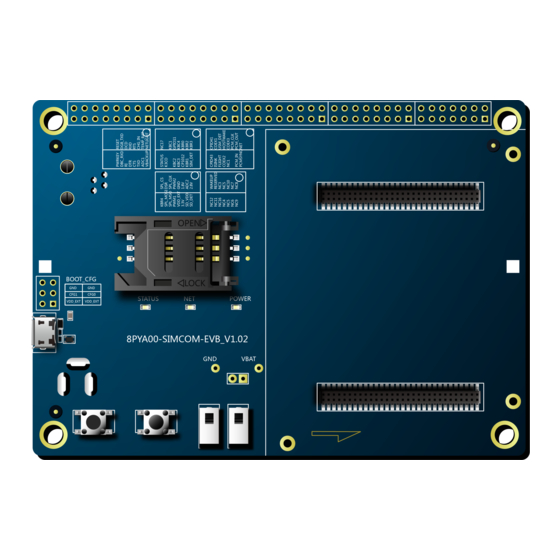
Smart Machine Smart Decision Figure2: SIMCOM-EVB BOTTOM view A: USB jack B: Powerkey C: Reset D: Power switch E: RF s witch F: TE connector G: TE connector H: SIMcard holder 1 LED indicator for Netlight LED indicator for Power... -
Page 8: Evb Accessory
Smart Machine Smart Decision 2. EVB Accessory Figure 3: EVB Accessory A: SIMCOM-EVB B: 5V DC adapter C: USB Cable D:GSM/WCDMA /LTE antenna SIMCOM_EVB Kit_User Guide_V1.01 2016-08-17... -
Page 9: Accessory Interface
Smart Machine Smart Decision 3. Accessory Interface 3.1 Power Interface Signal Description Adapter input 5V/2.0A DC source input 3.2 Audio Interface Figure4: Audio Interface Headset interface: Signal Description MICN Negative microphone input SPKN Negative receiver output SPKP Positive receiver output MICP Positive microphone input 3.3 SIM Card Interface... -
Page 10: Power Switch
Smart Machine Smart Decision Figure 5: Virtualserial port Enhanced COM port: AT communication Standard COM port: Debug CP2105 driver is available here: http://www.silabs.com/products/interface/usb-bridges/Pages/usb-bridges.aspx 3.5Power Switch After 5V Adapter inserted ,switch S201 on, then power LED (D201) willbe solid on. 3.6POWER_ON Button After give power to EVB,press the POWER_ON button for more than 1.5 seconds, the module will be turned on, the network LED light (D401) will blink. -
Page 11: Led Indicator
Smart Machine Smart Decision 3.8 LED Indicator LED light work’s behaviour as below. Name Description STATUS Bright:EVB Power ON; Power ON/OFF indicator D201 Extinct: EVB Power OFF NET status indicator Blinking at a certain frequency according various net status D401 Bright: Module runs normally D402 Module status indicator... -
Page 12: Test Interface
Smart Machine Smart Decision 4. Test Interface Figure 6: Test interface overview 4.1 Test Point A Figure 7:Test Point A Test point A Pin description: Signal Description PWRKEY Power on key RESET Reset key DBG_RXD Receive data DBG_TXD Transmit data Ring Indicator Data carrier detection Data Terminal Ready... -
Page 13: Test Point B
Smart Machine Smart Decision 4.2 Test Point B Figure8: Test Point B Test point B Pin description: Signal Description STATUS Module working on indicate NC17 KBC0 KEYPAD input KBC1 KEYPAD input KBC2 KEYPAD input GPIO11 GPIO KBC3 KEYPAD input KBC4 KEYPAD input GPIO12 GPIO... -
Page 14: Test Point C
Smart Machine Smart Decision 4.3 Test Point C Figure9: Test Point C Test point C Pin description: Signal Description KBR4 KEYPAD input SPI_CS SPI Chip Select SPI_MOSI SPI Data output Data Set Ready SPI_MISO SPI Data input SPI_CLK SPI Clock output PWM1 PWM output PWM2... -
Page 15: Test Point D
Smart Machine Smart Decision 4.4Test Point D Figure10: Test Point D Test point D Pin description: Signal Description GPIO43 GPIO GPIO41 GPIO ISINK Ground-referenced current sink. COEX1 RF synchronizing between Wi-Fi and LTE F LIGHT Flight mode SIM2_DET SIM detect COEX2 RF synchronizing between Wi-Fi and LTE HOST_WAKE... -
Page 16: Test Point E
Smart Machine Smart Decision 4.5Test Point E Figure11: Test Point E Test Point E Pin description: Signal Description NC12 WAKEUP_IN WAKEUP input NC11 RESERVED NC16 NC15 NC10 Note: please refer to specified TE schematic for test point if there has difference. SIMCOM_EVB Kit_User Guide_V1.01 2016-08-17... -
Page 17: Illustration
2) Take care with power to remove from SMA connector side slowly. 5.2Power on Module: Connect the SIMCOM-TE to the 2x60pins connector on EVB, plug in 5V DC adapter, switch S201 to “ON” state; keep S401 to “ON” position. Press the POWER_ON button for more than 1.5 second and then release, SIMCOM module power on.After the module is on, the LED light D402 will be bright ,and the LED light D401will blink at a certain frequency. -
Page 18: Registering Network And Making A Call
Smart Machine Smart Decision 5.3 Registering Network and Making a Call Install antenna to TE board, insert SIM card. Connect the USB cable to the USB jack; launch the Hyper Terminal in computer. Check the serial port number from Device Manager list. Use the Hyper Terminal to make a call from module as following: Launch hyper terminal configure right com port... - Page 19 Smart Machine Smart Decision configure baudrate Lastly connect the module and make a call. SIMCOM_EVB Kit_User Guide_V1.01 2016-08-17...
- Page 20 Smart Machine Smart Decision SIMCOM_EVB Kit_User Guide_V1.01 2016-08-17...
- Page 21 Smart Machine Smart Decision Contact us Shanghai SIMCom Wireless Solutions Ltd. Address: Building A, SIM Technology Building, No.633, Jinzhong Road, Changning District, Shanghai 200335 Tel: 86-21-32523300 Fax: 86-21-32523020 Email: simcom@sim.com Website:www.simcomm2m.com SIMCOM_EVB Kit_User Guide_V1.01 2016-08-17...
Need help?
Do you have a question about the EVB Kit and is the answer not in the manual?
Questions and answers