Table of Contents
Advertisement
Quick Links
Advertisement
Table of Contents

Related Manuals for SimCom TEKIT A7672X


Summary of Contents for SimCom TEKIT A7672X
- Page 1 A7672X & A7673X & A7677S TEKIT User Guide LTE Module SIMCom Wireless Solutions Limited SIMCom Headquarters Building, Building 3, No. 289 Linhong Road, Changning District, Shanghai P.R. China Tel: 86-21-31575100 support@simcom.com www.simcom.com...
- Page 2 PATENT, A UTILITY MODEL OR DESIGN. ALL SPECIFICATION SUPPLIED HEREIN ARE SUBJECT TO CHANGE WITHOUT NOTICE AT ANY TIME. SIMCom Wireless Solutions Limited SIMCom Headquarters Building, Building 3, No. 289 Linhong Road, Changning District, Shanghai P.R. China Tel: +86 21 31575100 Email: simcom@simcom.com...
-
Page 3: Version History
A7672X & A7673X & A7677S_TEKIT_User Guide_V1.01 Version History Date Version Description of change Author Chen Zhongyou 2023-07-04 1.00 Original Liu Xinao Liu Xinao 2023-08-02 1.01 Add Table 3, Table 4, Table 5, Table 6 Wang Tao www.simcom.com 3 / 26... -
Page 4: Table Of Contents
Figure Index..........................6 Introduction ........................7 Detail Description of TE ....................8 TE Accessory ......................... 11 Installing TE on SIMCom EVB Board ................12 TE KIT USB Driver Installation..................13 Using SIMCom Serial Port Tool ..................19 GNSS Antenna ....................... 20 Passive Antenna ......................... - Page 5 Table 4: ADC measurement range for R3 and R5 series modules ............25 Table 5: ADC measurement range for R2 series modules ..............25 Table 6: Resistors to be added to PT2 test points for R2 series modules ..........26 www.simcom.com 5 / 26...
- Page 6 Figure 13: Browse for the drivers ......................17 Figure 14: Schematic diagram of drivers’ successful installation ............18 Figure 15: SIMCom Serial Port Tool introduction ..................19 Figure 16: Passive antenna application ....................20 Figure 17: Active antenna application ....................... 21 Figure 18: Speaker application ........................
-
Page 7: Introduction
When utilizing the TE board, please ensure it is paired with the EVB board. The content of this document does not include information about the EVB board. For further details, please refer to the SIMCOM_EVB_KIT_User_Guide_V1.01. www.simcom.com 7 / 26... -
Page 8: Detail Description Of Te
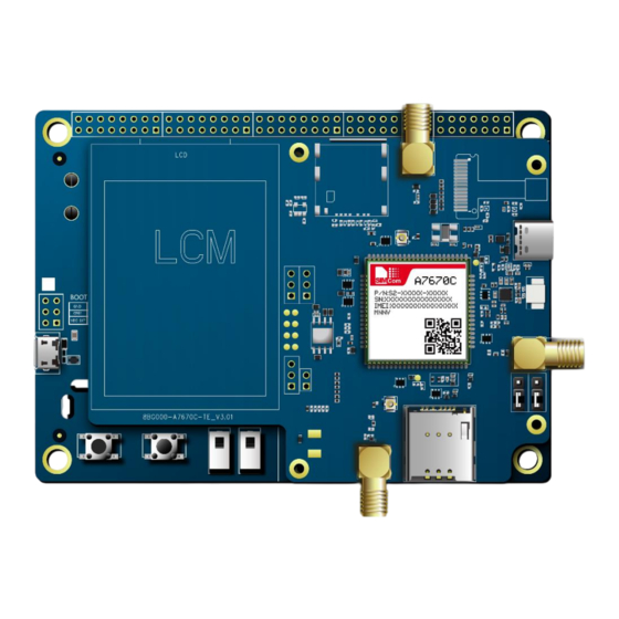
The TE board offers a variety of functional testing interfaces. The locations of these interfaces can be seen in Figures 1 and 2, while their explanations are provided in Table 1. Figure 1: Top view of TE board www.simcom.com 8 / 26... - Page 9 A7672X & A7673X & A7677S_TEKIT_User Guide_V1.01 Figure 2: Bottom view of TE board www.simcom.com 9 / 26...
- Page 10 Connector Camera Speaker Connector GNSS Antenna Debugging Connector Main Antenna Debugging Connector Connector (Connect to SIMCOM-EVB) Connector (Connect to SIMCOM-EVB) LCD Connector SD Card Slot NOTE If UART Switch connected to above two pins by jumper,the debug UART will connect to EVB;...
-
Page 11: Te Accessory
A7672X & A7673X & A7677S_TEKIT_User Guide_V1.01 3 TE Accessory The TE kit does not include any accessories. The main antenna is provided by the SIMCom EVB kit. www.simcom.com 11 / 26... -
Page 12: Installing Te On Simcom Evb Board
A7672X & A7673X & A7677S_TEKIT_User Guide_V1.01 4 Installing TE on SIMCom EVB Board TE kits are specifically designed to be compatible with the EVB board, and they are installed as shown in Figure 3. Figure 3: TE and SIMCom-EVB accessory www.simcom.com... -
Page 13: Te Kit Usb Driver Installation
Unzipping software. The installation package is shown in Figure 4. Figure 4: ASR drivers installation package Installing the software. If the installation is successful, it will be depicted in Figure 5. Figure 5: Software installation diagram www.simcom.com 13 / 26... - Page 14 Selecting “Browse my computer for drivers”. Selecting “Let me pick from a list of available drivers on my computer”. You will see the device’s type list. Finding “Ports(COM & LPT)” like Figure 7, then clicking “Next”. Figure 7: Device type list www.simcom.com 14 / 26...
- Page 15 A7672X & A7673X & A7677S_TEKIT_User Guide_V1.01 Finding “ASR Hefei”, then clicking “ASR Modem Device” as shown in Figure 8. Figure 8: Device driver Clicking “Next”, you will see “Update Driver warning”. Then click “yes”. Figure 9: Update driver warning www.simcom.com 15 / 26...
- Page 16 Then you need to install the other two drivers in the same way, but you need to choose the other models named “ASR Modem Device 2” and “ASR Serial Download Device” as shown in Figure 11 on the right. Figure 11: Other drivers installation method www.simcom.com 16 / 26...
- Page 17 11. Figure 12 shows that three drivers are installed successfully. Figure 12: Port list 12. Then you need to install the SIMCom’s drivers. Using the same way. Right clicking and selecting “Update driver”. Selecting “Browse my computer for drivers”. Clicking “Browse” and manually searching the driver folder, then click “Next”.
-
Page 18: Usb Ports
Table 2: USB ports and their description USB Ports Description SimTech HS-USB AT Port 9011 AT Command Communication Port SimTech HS-USB Diagnostics 9011 Software Debug and FW Update Port SimTech HS-USB Modem 9011 Modem Port for PPP www.simcom.com 18 / 26... -
Page 19: Using Simcom Serial Port Tool
A7672X & A7673X & A7677S_TEKIT_User Guide_V1.01 6 Using SIMCom Serial Port Tool SIMCom provides a serial port tool for testing modules using AT Commands. The Serial Port Tool enables communication with modules by opening COM Ports from a list. The following figure displays each section of the SIMCom Serial Port Tool. -
Page 20: Gnss Antenna
L1 and C1 positions remain NC. When using passive antennas, if the external DC power supply is provided, it will cause circuit abnormality and heating, in the GNSS part within the module. Figure 16: Passive antenna application www.simcom.com 20 / 26... -
Page 21: Active Antenna
2. For the TE board before August 1, 2023, the passive antenna scheme is used by default, C1 and L1 are NC by default. If you need to connect the active antenna, please manually solder the components on C1 and L1 position and make sure that 100pF isolation capacitor is soldered on R210 position. www.simcom.com 21 / 26... -
Page 22: Speaker
The TE board provides a speaker interface for playing audio. The audio amplifier supports a maximum output power of 2W. Therefore, select the speaker with the corresponding power according to the actual situation. Figure 18: Speaker application www.simcom.com 22 / 26... -
Page 23: Antenna Debugging Connector
0R resistance on the R231 position to the R232 position and remove the 0R resistance on the R233 position to the R234 position. J208 R232 R234 J209 Figure 19: Antenna debugging connector application www.simcom.com 23 / 26... -
Page 24: Adc
Table 6. In addition, it is recommended that the accuracy of the above resistors is 1%, otherwise the accuracy of reading the battery voltage may be poor. Figure 20: ADC test points PT1 and PT2 www.simcom.com 24 / 26... -
Page 25: Measurement Range
Table 4: ADC measurement range for R3 and R5 series modules Attachment Label Measurement Range ADC1 0-1.2V ADC2 0-1.2V Table 5: ADC measurement range for R2 series modules Attachment Label Measurement Range ADC1 0-1.8V ADC_VBAT 3.4-4.2V www.simcom.com 25 / 26... -
Page 26: Resistance Value
A7672X & A7673X & A7677S_TEKIT_User Guide_V1.01 Table 6: Resistors to be added to PT2 test points for R2 series modules Attachment Label Resistance value R223 680K R224 470K R228 www.simcom.com 26 / 26...
Need help?
Do you have a question about the TEKIT A7672X and is the answer not in the manual?
Questions and answers