GoPass AVL-901C Hardware Installation Manual
Gps vehicle tracker
Hide thumbs
Also See for AVL-901C:
- Package contents (2 pages) ,
- Supplementary manual (2 pages) ,
- Quick start manual (20 pages)

Subscribe to Our Youtube Channel
Related Manuals for GoPass AVL-901C


Summary of Contents for GoPass AVL-901C
-
Page 2: Table Of Contents
Table of Contents I. Working Directions ..............2 II. System Introduction .............. 3 III. Wiring and Installation ............5 1. Product Parts List..............5 2. Panel Description ..............7 3. Precaution before Installation ..........8 4. Installation .................9 5. Power Charging ..............12 6. -
Page 3: Working Directions
I. Working Directions Thank you for your purchase of AVL-901(C) GPS/ GPRS Locator Tracker. In order to realize the full functions of this product, please read this manual carefully before starting to use the product. 1. This product can only be maintained and repaired by qualified professional service personnel. -
Page 4: System Introduction
II. System Introduction AVL-901(C) is a high-tech product through cooperation with mobile operators. It combines GPS Global Positioning System and GSM/GPRS communication system, which can clearly inform you the position & situation of your car. GPS is the abbreviation for Global Positioning System, which is a product of the cold war between USA and USSR. - Page 5 Following are the function descriptions for the AVL-901(C) products. 1. GPS Position Tracking Function With this function, the vehicle owner will be able to know the geographic coordinates, speed, direction, and other related information of the car anytime in any place. The report methods can be via SMS short message service, or via GPRS.
-
Page 6: Wiring And Installation
III. Wiring and Installation 1. Product Parts List AVL Unit + GPRS Antenna GPS Antenna Control Keypad & SOS Cable Speaker Microphone Car Charging Cable... - Page 7 Quick Start Guide & Installation CD RS232-USB Cable (optional) GPRS Antenna Back-up Battery (optional)
-
Page 8: Panel Description
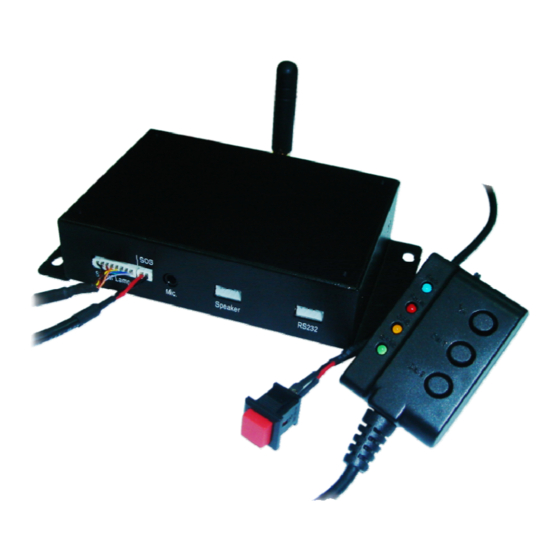
2. Panel Description On/ Off Switch for Park Function Park LED Answer/ Hang up Power LED Quick Dial1 GPS LED Quick Dial 2 GPRS LED Socket for Socket for Keypad Socket for Speaker & SOS Cable Microphone Connector for Power Switch GPRS/GSM Antenna Connector for Socket for... -
Page 9: Precaution Before Installation
3. Precaution before Installation Check if all the parts are included. Prepare a SIM card for GSM communication. Use some other mobile phone to confirm that the PIN code has not been set, and that it can dial out and receive telephone calls without problem. -
Page 10: Installation
4. Installation Step 1: Install GPRS Antenna * Connect the GPRS Antenna to the unit. * Fasten the connection by turning the screw in the bottom. Please do not swing round the antenna itself. Step 2: Install SIM Card 1). Unscrew and remove the back cover of your locator. 2). - Page 11 4). Insert the SIM card by sliding it into the card holder slot, with the chip module facing to the connectors on PCB, as shown in the picture. 5). Flip down the holder top. 6). Push the holder top leftward, and let it snap in completely. 7).
- Page 12 Step 3: Connect GPS Antenna GPS antenna is used to receive satellite signals in the sky. It should be positioned at a place where it will have an unobstructed view of the sky. The ideal location is top of the dashboard or close to the rear window of the car.
-
Page 13: Power Charging
5. Power Charging * This should be done by the professional technician. The AVL unit should be connected to power source, after all the wiring work has been completed and checked. GPS antenna is used to receive satellite signals in the sky. It should be fixed to face the sky;... -
Page 14: Description Of The Led Indicators
6. Description of the LED Indicators PARK POWER GPS STATUS GSM/GPRS (RED LED) (ORANGE LED) (GREEN LED) (BLUE LED) GSM is GPS is on, and Flash sending/receiving data position is fixed or phone call GSM is on, Geo-fence Constant function has normal but not yet connected Glow... -
Page 15: Operating Instructions
IV. Operating Instructions 1. Geo-fence (Park) Function Slide the Park switch to the left to activate Geo-fence function, the Blue LED will be “constant glow”. AVL-901(C) will send a SMS alert message to the preset phone numbers, if the car is moved beyond the preset distance range. Slide the Park switch back to the right, the Blue LED will shut off;... -
Page 16: Setting The Volume & Ring
5. Setting the Volume & Ring Press “ ” for 3-5 seconds, the device will ring up. By then, you Dial 1 Volume: can press Dial 1(+) or Dial 2(-) to adjust volume up/ down; and press “Pick-Up/ Hang-Up” button to confirm the setting. Ringing: Press “... -
Page 17: Hardware Specifications
V. Hardware Specifications 114x76x30 Dimensions (mm) GSM/GPRS Module Siemens TC65 EGSM900: TX880-915MHz, RX 925-960MHz DCS1800: TX 1710-1785MHz, RX 1805-1880MHz Bandwidth GSM850: TX824-849MHz, RX 869-894MHz GSM1900: TX1850-1910MHz, RX 1930-1990MHz Maximum EGSM900, GSM850: 33 dBm(2W) RF Output Power GSM1800, GSM1900: 30 dBm(1W) 50Ω... -
Page 18: Troubleshooting
VI. Troubleshooting 1. After AVL-901(C) installed, why there is no response? Check the polarity of power connection to see if a wrong polarity connected. Check the connection of back-up battery to see if it is properly installed. Check the power is on or not. 2. - Page 19 5. Does the weather affect GPS operation? GPS system is able to overcome weather problem in its initial design. GPS satellite positioning signals consist of short waves; the transmission of short waves will not be affected by weather conditions. GPS signals may produce error factors during transmission, such as solar wind, earth rotation, variation of aerosphere density, building reflection, etc.
Need help?
Do you have a question about the AVL-901C and is the answer not in the manual?
Questions and answers