Table of Contents
Advertisement
Advertisement
Table of Contents

Related Manuals for Keysight U3401A


Summary of Contents for Keysight U3401A
- Page 1 Keysight U3401A 4 1/2 Digit Dual Display Multimeter User’s and Service Guide...
-
Page 2: Safety Information
FAR 27.401 or DFAR 227.7103-5 (c), as applicable in any Do not proceed beyond a WARNING technical data. notice until the indicated conditions are fully understood and met. Keysight U3401A User’s and Service Guide... -
Page 3: Safety Symbols
Frame or chassis (ground) terminal IEC Measurement Category II. Measurement performed on circuits that are directly connected to the low CAT II voltage installation (up to 300 VAC) 300 V under Category II overvoltage conditions Keysight U3401A User’s and Service Guide... -
Page 4: General Safety Information
Failure to comply with these precautions or with specific warnings elsewhere in this manual violates safety standards of design, manufacture, and intended use of the instrument. Keysight Technologies assumes no liability for the customer’s failure to comply with these requirements. - Page 5 Remove power and do not use the product until safe operation can be verified by service-trained personnel. If necessary, return the product to Keysight Technologies Sales and Service Office for service and repair to ensure the safety features are maintained.
-
Page 6: Environmental Conditions
–20 °C to 60 °C (Non-operating) Altitude Operating up to 2,000 metres (6,562 feet) Pollution degree Pollution Degree 2 The Keysight U3401A dual display complies with the following EMC NOTE requirements: – IEC 61010-1:2001/EN61010-1:2001 (2nd Edition) – Canada: CAN/CSA-C22.2 No. 61010-1-04 –... -
Page 7: Regulatory Markings
The CSA mark is a registered substance elements are expected to trademark of the Canadian leak or deteriorate during normal use. Standards Association. Forty years is the expected useful life of the product. Keysight U3401A User’s and Service Guide... -
Page 8: Waste Electrical And Electronic Equipment (Weee) Directive 2002/96/Ec
To return this unwanted instrument, contact your nearest Keysight Service Center, or visit http://about.keysight.com/en/companyinfo/environment/takeback.shtml for more information. Sales and Technical Support To contact Keysight for sales and technical support, refer to the support links on the following Keysight websites: – www.keysight.com/find/low-cost-dmm (product-specific information and support, software and documentation updates) –... -
Page 9: Table Of Contents
........8 Getting Started Introducing the Keysight U3401A Dual Display Multimeter ..18 Checking the shipping contents . - Page 10 ........85 Keysight U3401A User’s and Service Guide...
- Page 11 ....... .95 Characteristics and Specifications Keysight U3401A User’s and Service Guide...
- Page 12 THIS PAGE HAS BEEN INTENTIONALLY LEFT BLANK. Keysight U3401A User’s and Service Guide...
- Page 13 Connection terminal when measuring DC voltage and AC ripple ......65 Keysight U3401A User’s and Service Guide...
- Page 14 ......67 Figure 3-4 Connection terminal when measuring Resistance . . . 68 Keysight U3401A User’s and Service Guide...
- Page 15 .......87 Table 5-2 Type of current input fuse ..... .88 Keysight U3401A User’s and Service Guide...
- Page 16 THIS PAGE HAS BEEN INTENTIONALLY LEFT BLANK. Keysight U3401A User’s and Service Guide...
-
Page 17: Getting Started
Stacking the U3401A Adjusting the Handle Product at a Glance Making measurements Selecting a Range This chapter provides an introduction to the U3401A digital multimeter and a tutorial showing how to use the front panel in order to make measurements. -
Page 18: Introducing The Keysight U3401A Dual Display Multimeter
Getting Started Introducing the Keysight U3401A Dual Display Multimeter The key features of the U3401A dual display multimeter are: – 4 ½-digit dual display measurement – Ten measurement functions: – AC voltage – DC voltage – AC current – DC current –... -
Page 19: Checking The Shipping Contents
Keysight Technologies office. Keep the damaged shipping materials (if any) for inspection by the carrier and Keysight representative. If required, you can find a list of Keysight Sales and Service Offices on the last page of this guide. -
Page 20: Connecting Power To The Instrument
If self-test is successful, the multimeter goes to normal operation. If the self-test fails, either a full annunciator or a blank display is displayed without entering the normal operation. If the self-test repeatedly fails, contact your nearest Keysight Sales and Service Office. -
Page 21: Stacking The U3401A
The U3401A is shipped with specially designed anti-slip protective bumpers on the front and rear panel. The multimeters will not slide off when stacked on top of each other. To be able to stack the U3401A multimeters, ensure the attached bumpers are in correct orientation. See Figure 1-1. -
Page 22: Adjusting The Handle
Type of handle position To attach or detach the handle, rotate the handle upright and pull it out from the sides of the multimeter. Refer to Figure 1-3. Figure 1-3 Attaching and detaching the handle Keysight U3401A User’s and Service Guide... -
Page 23: Product At A Glance
Getting Started Product at a Glance Product dimensions Front view 226.0 mm Side view 105.0 mm 305.0 mm Figure 1-4 U3401A dimensions Keysight U3401A User’s and Service Guide... -
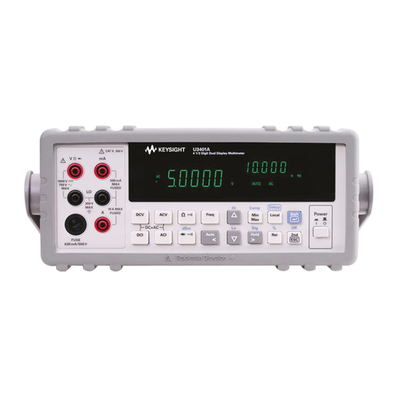
Page 24: The Front Panel At A Glance
The front panel at a glance Primary display Secondary display Measurement Autoranging, Input terminals Math Shift Power function manual range, and current fuse operation on/off keypads and comparator keypads switch operation Figure 1-5 Front panel Keysight U3401A User’s and Service Guide... -
Page 25: The Display At A Glance
Table 1-1 Display annunciators Annunciator Description Primary d isplay Reading rate: Slow. Not applicable for the U3401A. Reading rate: Medium. Not applicable for the U3401A. Reading rate: Fast. Not applicable for the U3401A. PEAK Peak measurement. Not applicable for the U3401A. -
Page 26: Table 1-1 Display Annunciators
Duty cycle measurement Voltage unit: mV, V μmA Current unit: μA, mA, A Shift mode MkΩ Resistance unit: Ω, kΩ, MΩ Secondary display is enabled. Not applicable for the U3401A. AUTO Autoranging Direct current Alternating current Keysight U3401A User’s and Service Guide... - Page 27 External. Not applicable for the U3401A. TRIG Trigger mode REMOTE Remote interface control. For calibration use only. LOCAL Local mode Store instrument state. Not applicable for the U3401A. Recall stored instrument state. Not applicable for the U3401A. Keysight U3401A User’s and Service Guide...
-
Page 28: The Keypad At A Glance
Keypad functions Description System related operation Press to power-on or power-off the U3401A multimeter. Press to select Shift. Press to return the multimeter to front panel operation when it is in remote state. Press to step through the Setup menu. See “Using the setup menu”... -
Page 29: Table 1-2 Keypad Functions
– Press to select the reference impedance for dBm measurement. Press to toggle between manual ranging and autoranging. Press to select a higher range and disable autoranging. See “Selecting a Range” on page 43 for more information. Keysight U3401A User’s and Service Guide... - Page 30 Press to enable Hold math operation. See “Hold” on page 53 on for more information. Press to enable the MinMax math operation. Press to select the Relative math operation. Press to select the Percentage operation. Keysight U3401A User’s and Service Guide...
-
Page 31: The Terminals At A Glance
NOTE mains. However, transient overvoltages are also present on circuits that are isolated from mains. The Keysight U3401A is designed to safely withstand occasional transient overvoltages up to 2500 V PEAK. Do not use this multimeter to measure circuits where transient overvoltages could exceed this level. -
Page 32: Table 1-3 Input Terminal For Different Functions
>10 A DC RMS for 20 seconds maximum Resistance (Ω) 500 VDC or AC RMS Diode test, continuity test 500 VDC or AC RMS All functions Any terminal to earth 1000 VDC or AC PEAK Keysight U3401A User’s and Service Guide... -
Page 33: The Rear Panel At A Glance
The rear panel at a glance AC line Line voltage fuse voltage selector selection table AC power AC line fuse Chassis RS232 interface connector connector ground lug (For calibration use only) Figure 1-9 Rear panel Keysight U3401A User’s and Service Guide... -
Page 34: Making Measurements
DC measurements of volts, amperes, or ohms; to achieve accurate measurement. This is due to the thermal voltages generated during the high current measurements that may cause errors when measuring the low-level measurements. Keysight U3401A User’s and Service Guide... -
Page 35: Performing Voltage Measurements
3 Probe the test points and read the display. In autoranging mode, the multimeter automatically selects the appropriate range and the measurement is displayed. voltage source – Figure 1-10 ACV terminal connection and display Keysight U3401A User’s and Service Guide... -
Page 36: Figure 1-11 Dcv Terminal Connection And Display
3 Probe the test points and read the display. In autoranging mode, the multimeter automatically selects the appropriate range and the measurement is displayed. voltage source – Figure 1-11 DCV terminal connection and display Keysight U3401A User’s and Service Guide... -
Page 37: Performing Current Measurements
4 Probe the test points in series with the circuit. 5 Power on the measured circuit and read the display. ACI or DCI current source – Figure 1-12 ACI RMS or DCI (mA) terminal connection and display Keysight U3401A User’s and Service Guide... -
Page 38: Figure 1-13 Aci Rms Or Dci (10A) Terminal Connection And
5 Probe the test points in series with the circuit. 6 Power on the measured circuit and read the display. – ACI or DCI current source Figure 1-13 ACI RMS or DCI (10A) terminal connection and display Keysight U3401A User’s and Service Guide... -
Page 39: Performing Frequency Measurements
3 Probe the test points and read the display. In autoranging mode, the multimeter automatically selects the appropriate range and the measurement is displayed. Frequency source – Figure 1-14 Frequency terminal connection and display Keysight U3401A User’s and Service Guide... -
Page 40: Performing Resistance/Continuity Measurements
3 Probe the test points (by shunting the resistor) and read the display. In autoranging mode, the multimeter automatically selects the appropriate range and the measurement is displayed. Test current Resistance – Figure 1-15 Resistance /continuity terminal connection and display Keysight U3401A User’s and Service Guide... -
Page 41: Performing Diode And Continuity Test
5 Reverse the probes and measure the voltage across the diode again as shown Figure 1-17. Assess the diode according to the following guidelines: – A diode is considered good if the multimeter displays OL in reverse bias mode. Keysight U3401A User’s and Service Guide... -
Page 42: Figure 1-16 Forward-Biased Diode/Continuity Test Terminal Connection And Display
– A diode is considered open if the multimeter displays OL in both forward and reverse bias modes. Test current Forward bias – Figure 1-16 Forward-biased diode/continuity test terminal connection and display Test current Reverse bias – Figure 1-17 Reverse-biased diode/continuity terminal connection and display Keysight U3401A User’s and Service Guide... -
Page 43: Selecting A Range
– Autorange thresholds - The multimeter shifts ranges as follows: – Down range at < 5% of current range. – Up range at > full scale of current range. – Table 1-4 shows the summary of range scale values respectively. Keysight U3401A User’s and Service Guide... - Page 44 Fixed range 500.000, 5.000 k, 50.000 k, 500.000 k, 5.000 M, 50.000 MΩ Continuity (Continuity Mode) Notes: [a] You are required to select the range manually when a signal is applied to the A terminal. Keysight U3401A User’s and Service Guide...
- Page 45 Keysight U3401A 4 ½ Digit Dual Display Multimeter User’s and Service Guide Operations and Features Operating Math Functions Using the Secondary Display This chapter explains the various functions and features available on the U3401A digital multimeter.
-
Page 46: Operations And Features
– All math operations are automatically turned-off when changing the measurement functions. – Range changing is allowed for all math operations. Keysight U3401A User’s and Service Guide... -
Page 47: Dbm
The multimeter displays the dBm modifier on the primary display and displays the reference impedance selection on the secondary display. Procedure 1 1 Press to enable the dBm modifier mode and dBm operation. 2 Use to select the desired reference impedance. Keysight U3401A User’s and Service Guide... -
Page 48: Rel
When the Rel operation is enabled in autoranging mode, enabling the Comp or Percentage operation will disable the Rel operation. Procedure 1 Press to exit the relative mode. Figure 2-2 Typical Rel operation display Keysight U3401A User’s and Service Guide... -
Page 49: Minmax
(if the beeper is enabled) and briefly turns on the appropriate MAX or MIN annunciator. Accumulated statistics are: – MAX—maximum reading since MinMax was enabled – MIN—minimum reading since MinMax was enabled – MINMAX—actual readings Keysight U3401A User’s and Service Guide... - Page 50 2 Press continuously until the desired operation appear. The MinMax operation will display MINMAX > MAX > MIN > MINMAX in sequence when this key is press continuously. 3 Press to disable the MinMax operation. Keysight U3401A User’s and Service Guide...
-
Page 51: Comp
59), the beeper beeps three tones on the transition from PASS to HI or LO. When transitioning from HI or LO to PASS, it will only beep once. – Press to enable Comp operation. Keysight U3401A User’s and Service Guide... - Page 52 The lower limit is shown on primary display while the LO annunciator is shown on secondary display. 5 Use , and to modify the lower limit. 6 Press to store the specified LO limit value. Keysight U3401A User’s and Service Guide...
-
Page 53: Hold
Procedure 1 Press to access to the Setup menu. 2 Use to select the rHold. 3 Press to enter the second tier menu. Use to set the state to ON. Keysight U3401A User’s and Service Guide... -
Page 54: Figure 2-7 Typical Refresh Hold Operation Display
– For voltage and current measurements, the held value will not be updated NOTE when the reading is below 500 counts. – For resistance and diode measurements, the held value will not be updated when the reading is at OL or open state. Keysight U3401A User’s and Service Guide... -
Page 55: Percentage (%)
– The secondary display shows OL when readings exceed the maximum display of 999.99%. – When autoranging is enabled, this operation will be used to lock the current range. Keysight U3401A User’s and Service Guide... - Page 56 The lower limit is shown on primary display while the LO annunciator is shown on secondary display. 5 Use , and to modify the lower limit. 6 Press to store the specified LO limit value. 7 Press to enable percentage operation. 8 Press to disable percentage operation. Keysight U3401A User’s and Service Guide...
-
Page 57: Using The Secondary Display
Table 2-2 on page 58. To disable the secondary display mode: Press . The display will remain in primary display mode. Keysight U3401A User’s and Service Guide... - Page 58 [b] In autoranging mode, the ranges setting of both the primary and secondary display are corresponding to the higher range of two displays. Whereas in manual range, the ranges of secondary display are the same as the primary display. Keysight U3401A User’s and Service Guide...
-
Page 59: Using The Setup Menu
600, 700, 800, 900, 1000. Notes: [a] For calibration use only. [b] Variation count is used to recognize new value will be updated once the variation of measuring value is esceeded the setting value. Keysight U3401A User’s and Service Guide... -
Page 60: Changing The Configurable Settings
6 After saving the changes, press to quit from the tier menu. 7 Press again to quit from the setup menu. 8 The configuration settings is saved and main display is displayed. Keysight U3401A User’s and Service Guide... -
Page 61: Trigger Mode
3 Press to get a new value again. 4 Press to select autoranging or manual range as necessary. 5 Press to disable external trigger operation mode. Figure 2-10 Typical trigger mode display Keysight U3401A User’s and Service Guide... - Page 62 – All math operations will be disabled when external trigger is enabled. NOTE – Press may also disable external trigger. – Both the primary and secondary display will only appear when frequency operation is selected in trigger mode. Keysight U3401A User’s and Service Guide...
-
Page 63: Application Tutorial
Keysight U3401A 4 ½ Digit Dual Display Multimeter User’s and Service Guide Application Tutorial Applications for Using Dual Display Dual Display Operation Examples This chapter describes the advanced features and the possible applications for effective operation of the multimeter. -
Page 64: Applications For Using Dual Display
– Measuring AC ripple and DC current of power supply. – Measuring current dissipation for power supply analysis. ACI + DCI Reference Ω – Setting dB reference impedance and show dBm. – Indicating DC voltage and dBm. – Indicating AC voltage and dBm. Keysight U3401A User’s and Service Guide... -
Page 65: Dual Display Operation Examples
NOTE – Press to disable the secondary display. – Press to select the suitable range if DCV+ACV ripple is above the scale of the current range. Keysight U3401A User’s and Service Guide... -
Page 66: Measure Ac And Dc Current On A Rectification Circuit
AC current measurement for primary display. 3 Press to enable the DC current measurement for secondary display. 4 Press to select autoranging or manual range for secondary display. NOTE Press to disable the secondary display. Keysight U3401A User’s and Service Guide... -
Page 67: Measure Ac Voltage And Frequency On An Ac Circuit
AC voltage measurement for primary display. 3 Press to select frequency measurement for secondary display. 4 Press to select autoranging or manual range for secondary display. NOTE Press to disable the secondary display. Keysight U3401A User’s and Service Guide... -
Page 68: Measure Resistance
LO input terminals as shown in Figure 3-4. Resistance – Figure 3-4 Connection terminal when measuring Resistance 2 Press to select resistance measurement. 3 Press . Use to select autoranging or manual range for primary display. Keysight U3401A User’s and Service Guide... -
Page 69: Measure True Rms Ac + Dc
AC+DC RMS value using the quation below: AC+DC (RMS) = + AC When AC+DC voltage measurement is selected, the DCV input impedance is NOTE paralleled with the AC coupled 1.1 MΩ AC divider. Keysight U3401A User’s and Service Guide... - Page 70 Application Tutorial THIS PAGE HAS BEEN INTENTIONALLY LEFT BLANK. Keysight U3401A User’s and Service Guide...
-
Page 71: Performance Test
Keysight U3401A 4 ½ Digit Dual Display Multimeter User’s and Service Guide Performance Test Calibration Overview Recommended Test Equipment Test Considerations Performance Verification Tests Overview This chapter contains performance test procedures and calibration procedures. The performance tests procedures allow you to verify that the multimeter is operating within its published specifications. -
Page 72: Calibration Overview
74 before calibrating the NOTE instrument. Keysight Technologies calibration services When your instrument is due for calibration, contact your local Keysight Service Center. The U3401A is supported on automated calibration systems at Keysight service centres only. Calibration interval A one-year interval is adequate for most applications. -
Page 73: Recommended Test Equipment
If the exact instrument is not available, substitute calibration standards of equivalent accuracy. A suggested alternate method would be to use the Keysight 3458A 8½ -digit digital multimeter to measure less accurate yet stable sources. The output value measured from the source can be entered into the instrument as the target calibration value. -
Page 74: Test Considerations
Please ensure that the calibration standards and test procedures used do not NOTE introduce additional errors. Ideally, the standards used to verify and adjust the instrument should be an order of magnitude more accurate than each instrument range full-scale error specification. Keysight U3401A User’s and Service Guide... -
Page 75: Performance Verification Tests Overview
After acceptance, you should repeat the performance verification tests at every calibration interval. If the instrument fails performance verification, adjustment or repair is required. Contact your local Keysight Service Center for details. Make sure you have read “Test Considerations”... -
Page 76: Table 4-2 Dc Voltage Verification Test
4-3. 3 Make a measurement and observe the result. Compare measurement results to the appropriate test limits shown in Table 4-3. (Be certain to allow for appropriate source settling when using the Fluke 5520A). Keysight U3401A User’s and Service Guide... -
Page 77: Table 4-3 Dc Current Verification Test
±0.26 mA 0.0000 A ±0.5 mA 0.000 A 10 A ±5 mA 4.5000 A ±11.7 mA 9.000 A 10 A ±27 mA Connect calibrator to multimeter’s A and Lo terminals before applying 10 A. CAUTION Keysight U3401A User’s and Service Guide... -
Page 78: Table 4-4 2-Wire Ω Verification Test
450.00 kΩ 500 kΩ ±480 Ω 4.5000 MΩ 5 MΩ ±4.8 kΩ 30.000 MΩ 50 MΩ ±93 kΩ Notes: [a] Specifications are for 2-wire ohms function using the Rel operation enabled to eliminate lead resistance. Keysight U3401A User’s and Service Guide... - Page 79 Table 4-6. (Be certain to allow for appropriate source settling). Table 4-6 Frequency verification test Function Vol tage Input frequency Range Error from nominal one year Frequency 4.5 kHz 5 kHz ±0.7 Hz Keysight U3401A User’s and Service Guide...
-
Page 80: Ac Voltage Verification Test
±2.4 V 75.0 V 1 kHz 750 V ±1.8 V 675.0 V 1 kHz 750 V ±4.8 V Set the calibrator output to 0 V before disconnecting it from the multimeter CAUTION input terminals. Keysight U3401A User’s and Service Guide... -
Page 81: Ac Current Verification Test
1 kHz 500 mA ±2.45 mA 0.5000 A 1 kHz ±5.5 mA 1.000 A 1 kHz 10 A ±35 mA 4.5000 A 1 kHz ±25.5 mA 9.000 A 1 kHz 10 A ±75 mA Keysight U3401A User’s and Service Guide... - Page 82 Performance Test THIS PAGE HAS BEEN INTENTIONALLY LEFT BLANK. Keysight U3401A User’s and Service Guide...
- Page 83 Keysight U3401A 4 ½ Digit Dual Display Multimeter User’s and Service Guide Disassembly and Repair Operating Checklist Types of Service Available Mechanical Disassembly Replaceable Parts This chapter will help you troubleshoot a faulty multimeter. It describes how to disassemble the multimeter, how to obtain repair services, and lists the...
-
Page 84: Disassembly And Repair
Disassembly and Repair Operating Checklist Before returning your multimeter to Keysight for service or repair check the following items: Is the multimeter inoperative? Verify the power line voltage setting. Verify the power line fuse is installed. Check the power cord is connected to multimeter and to AC line power. -
Page 85: Types Of Service Available
Disassembly and Repair Types of Service Available If your instrument fails during the warranty period, Keysight Technologies will repair or replace it under the terms of your warranty. After your warranty expires, Keysight offers repair services at competitive prices. Extended service contracts Many Keysight products are available with optional service contracts that extend the covered period after the standard warranty expires. -
Page 86: Repackaging For Shipment
Disassembly and Repair Repackaging for shipment If the instrument is to be shipped to Keysight for service or repair, be sure to: – Attach a tag to the unit identifying the owner and indicating the required service or repair. Include the model number and full serial number. -
Page 87: To Replace The Power Line Fuse
2 and pull the fuse holder from rear panel. 4 Replace fuse holder assembly in 3 Rotate the line voltage selector and reinstall it back, so that the correct voltage rear panel. appears in the fuse holder window. Keysight U3401A User’s and Service Guide... -
Page 88: To Replace A Current Input Fuse
– Use a conductive wrist strap to reduce static charge accumulation. – Minimize handling. – Keep replacement parts in original static-free packaging. – Remove all plastics, foam, vinyl, paper, and other static-generating materials from the immediate work area. – Use only anti-static solder suckers. Keysight U3401A User’s and Service Guide... -
Page 89: Mechanical Disassembly
General Disassembly 1 Remove power and all cables from the instrument. 2 Remove the carrying handle by rotating the handle upright and pulling out from the sides of the instrument. Keysight U3401A User’s and Service Guide... - Page 90 3 Remove the instrument bumpers. Pull from a corner and stretch the bumpers off the instrument. 4 Remove the rear bezel. Loosen the two captive screws in the rear bezel and remove the rear bezel. Keysight U3401A User’s and Service Guide...
- Page 91 1 Remove on/off switch push rod. Gently move the power switch push rod toward the front of the instrument to disengage it from the switch. Be careful not to twist or bend the push rod. Keysight U3401A User’s and Service Guide...
- Page 92 Disassembly and Repair 2 Remove the screw hold ing the front panel. 3 Disconnect the two ribbon cable connectors from the front panel. Keysight U3401A User’s and Service Guide...
- Page 93 4 Disconnect the individual front panel wires shown below. 25 A current fuse 5 There is now enough play to allow the side of the front panel to be pried from the chassis and removed as an assembly. Keysight U3401A User’s and Service Guide...
- Page 94 1 Remove the keyboard and d isplay assembly. Remove the two screws holding the circuit board. Lift the keyboard and display assembly from the plastic housing. a The rubber keypad can now be pulled from the plastic housing. Keysight U3401A User’s and Service Guide...
-
Page 95: Replaceable Parts
To order replaceable parts from Keysight, do the following: 1 Contact your nearest Keysight Sales Office or Service Center. 2 Identify the parts by the Keysight part number shown in the support parts list. 3 Provide the instrument model number and serial number. - Page 96 Disassembly and Repair THIS PAGE HAS BEEN INTENTIONALLY LEFT BLANK. Keysight U3401A User’s and Service Guide...
-
Page 97: Specifications
Keysight U3401A 4 ½ Digit Dual Display Multimeter User’s and Service Guide Characteristics and Specifications For the characteristics and specifications of the U3401A 4 ½ Digit Dual Display Multimeter, refer to the datasheet at http://literature.cdn.keysight.com/litweb/pdf/5990-3970EN.pdf. - Page 98 Characteristics and Specifications THIS PAGE HAS BEEN INTENTIONALLY LEFT BLANK. Keysight U3401A User’s and Service Guide...
- Page 99 This information is subject to change without notice. Always refer to the Keysight website for the latest revision. © Keysight Technologies 2009 - 2017 Edition 14, November 1, 2017 Printed in Malaysia *U3401-90001* U3401-90001 www.keysight.com...
Need help?
Do you have a question about the U3401A and is the answer not in the manual?
Questions and answers