Table of Contents
Advertisement
Quick Links
Advertisement
Table of Contents

Related Manuals for Keysight U1270 Series


Summary of Contents for Keysight U1270 Series
- Page 1 Keysight U1270 Series Handheld Digital Multimeters Service Guide...
-
Page 3: U1270 Series Service Guide
U1271-90020 ity and fitness for a particular purpose. age to the product or loss of impor- Keysight shall not be liable for errors or for Edition tant data. Do not proceed beyond a incidental or consequential damages in... -
Page 4: Safety Symbols
CAT III Both direct and alternating current Category III 1000 V overvoltage protection 1000 V CAT IV Earth (ground) terminal Category IV 600 V overvoltage protection 600 V Equipment protected throughout by double insulation or reinforced insulation U1270 Series Service Guide... -
Page 5: Safety Considerations
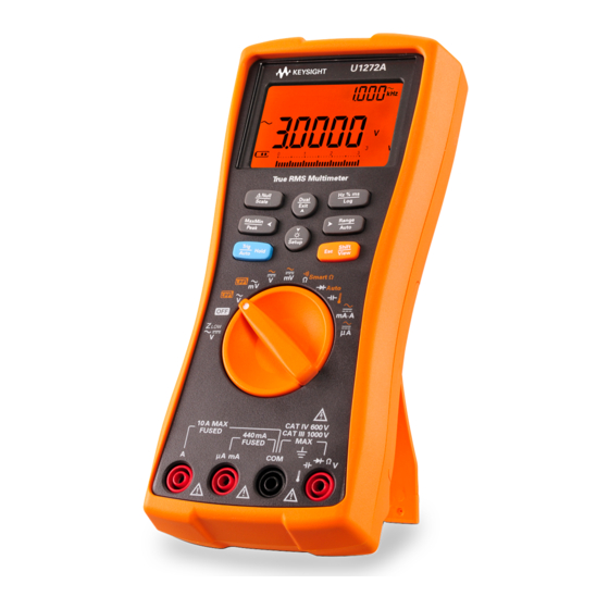
Safety Considerations Read the information below before using this multimeter. The descriptions and instructions in this manual apply to the Keysight U1271A, U1272A, U1273A, and U1273AX Handheld Digital Multimeters (hereafter referred to as the multimeter). The U1273A and U1272A models appear in all illustrations. - Page 6 • To avoid false readings, which may lead to possible electric shock or personal injury, replace the battery as soon as the low battery indicator appears and flashes. U1270 Series Service Guide...
-
Page 7: Environmental Conditions
• Up to 95% RH at 40 °C (non-condensing) Altitude Up to 3000 m Pollution degree Pollution degree II The U1270 Series Handheld Digital Multimeters comply with the following safety N O T E and EMC requirements: • Safety • EN/IEC 61010-1:2001 •... - Page 8 The CSA mark is a registered substance elements are expected to trademark of the Canadian Standards leak or deteriorate during normal use. Association. Forty years is the expected useful life of the product. U1270 Series Service Guide...
- Page 9 “Monitoring and Control Instrument” product. The affixed product label is as shown below. Do not dispose in domestic household waste. To return this unwanted instrument, contact your nearest Keysight Service Centre, or visit www.keysight.com/environment/product for more information.
- Page 10 Declaration of Conformity (DoC) The Declaration of Conformity (DoC) for this instrument is available on the Keysight Web site. You can search the DoC by its product model or description at the Web address below. http://regulations.products.keysight.com/DoC/search.htm If you are unable to search for the respective DoC, please contact your N O T E local Keysight representative.
-
Page 11: Table Of Contents
To change the calibration security code To reset the calibration security code to its factory default Using the Front Panel for Adjustments Adjustment considerations Valid adjustment input values Adjustment procedure Exiting the adjustment mode Calibration Count Calibration Error Codes U1270 Series Service Guide... - Page 12 Service and Maintenance Troubleshooting Checking the Fuse Fuse Replacement Returning the Instrument for Service Replaceable Parts To order replaceable parts Types of Service Available Extended service contracts Obtaining Repair Service (Worldwide) U1270 Series Service Guide...
- Page 13 Figure 1-8 Reference value display 47 Figure 2-1 Testing Fuse 1 55 Figure 2-2 Testing Fuse 2 56 Figure 2-3 Replacing Fuse 1 58 Figure 2-4 Replacing Fuse 2 59 Figure 2-5 Positions of Fuse 1 and Fuse 2 60 U1270 Series Service Guide...
- Page 14 THIS PAGE HAS BEEN INTENTIONALLY LEFT BLANK. U1270 Series Service Guide...
- Page 15 List of Tables Table 1-1 Recommended test equipment 20 Table 1-2 Performance verification tests 28 Table 1-3 Adjustment input values 43 Table 1-4 Calibration error codes 50 Table 2-1 Operating checklist 52 Table 2-2 Fuse displayed readings 54 U1270 Series Service Guide...
- Page 16 THIS PAGE HAS BEEN INTENTIONALLY LEFT BLANK. U1270 Series Service Guide...
-
Page 17: Calibration Procedures
U1270 Series Handheld Digital Multimeters Service Guide Calibration Procedures Calibration Overview 18 Closed-case calibration 18 Keysight calibration services 18 Calibration interval 19 Adjustment is recommended 19 Recommended Test Equipment 20 Basic Operating Test 22 Backlight test (U1271A/U1272A only) 22 Display test 22... -
Page 18: Calibration Overview
Calibration Procedures Calibration Overview Calibration Overview This manual contains procedures to verify the U1270 Series handheld digital multimeters performance and to perform adjustments (calibration). The performance test procedures allow you to verify that the instrument is operating within its published specifications. The adjustment procedures ensure that the instrument remains within its specifications until the next calibration. -
Page 19: Calibration Interval
A 1- year interval is adequate for most applications. Accuracy specifications are warranted only if adjustment is made at regular calibration intervals. Accuracy specifications are not warranted beyond the 1- year calibration interval. Keysight does not recommend extending calibration intervals beyond 2 years for any application. -
Page 20: Recommended Test Equipment
(Table 1- 1). If the exact instrument is not available, substitute with another calibration standard of equivalent accuracy. A suggested alternative method is to use the Keysight 3458A 8½ Digit Digital Multimeter to measure less accurate but stable sources. The output value measured from the source can be entered into the instrument as the target calibration value. - Page 21 Recommended Test Equipment Table 1-1 Recommended test equipment (continued) Recommended Application Recommended accuracy requirements equipment <20% of the U1270 Series accuracy Temperature Fluke 5520A specification Shorting plug — a dual banana plug with a copper wire Short shorting the two terminals Keysight —...
-
Page 22: Basic Operating Test
(OFF to ON). For U1273A/U1273AX models: Check that all the OLED pixels are lit. Verify that there are no dead pixels. Press any key to exit this mode. Figure 1-1 U1273A/U1273AX OLED display screen U1270 Series Service Guide... -
Page 23: Current Terminal Input Test
The multimeter sounds a continuous alert beep when the test lead is inserted into the A terminal but the rotary switch is not set to the function. The multimeter displays an input warning error (Figure 1- 3). Figure 1-3 Input warning display (A terminal) U1270 Series Service Guide... -
Page 24: Figure 1-4 Input Warning Display (Μa Ma Terminal)
µA mA terminal or until the rotary switch is set to the function. Before conducting this test, ensure that the beep function is not disabled N O T E in the multimeter’s setup. U1270 Series Service Guide... -
Page 25: Calibration Process
6 Secure the instrument against unauthorized calibration; see “Exiting the adjustment mode” on page 48. Ensure that the instrument has quit the adjustment mode and is turned off. 7 Record the new security code and calibration count in the instrument's maintenance records. U1270 Series Service Guide... -
Page 26: Test Considerations
Keep the input cables as short as possible. Long test leads can also act as antennas which may pick up AC signals. • Connect the input cable shields to earth ground. U1270 Series Service Guide... -
Page 27: Performance Verification Tests
If the instrument fails the performance verification tests, adjustment or repair is required. Ensure that you have read the “Test Considerations” on page 26 before N O T E running the performance verification tests. U1270 Series Service Guide... -
Page 28: Table 1-2 Performance Verification Tests
U1272A/U1273A/U1273AX, then turn the U1272A/U1273A/U1273AX rotary switch to the position before proceeding with the following Z functional test. U1252B input 1000 V 1.67 kΩ ±0.167 kΩ Turn the rotary switch to the position. [1] Functional test only. U1270 Series Service Guide... - Page 29 270 V, 20 kHz ±5.80 V 1000 V 1000 V, 45 Hz ±9.0 V ±8.0 V 1000 V, 65 Hz ±9.0 V ±8.0 V 1000 V, 1 kHz ±12.5 V ±12.5 V 1000 V, 5 kHz ±17.5 V U1270 Series Service Guide...
- Page 30 300 mV, 65 Hz ±2.30 mV ±2.00 mV 300 mV, 1 kHz ±3.25 mV ±2.35 mV 300 mV, 5 kHz ±6.25 mV ±3.25 mV 300 mV, 20 kHz ±6.40 mV ±3.40 mV 300 mV, 100 kHz ±10.90 mV U1270 Series Service Guide...
- Page 31 27 V, 100 kHz ±1.017 V 300 V 300 V, 45 Hz ±2.35 V 300 V, 65 Hz ±2.35 V 300 V, 1 kHz ±3.60 V 300 V, 5 kHz ±5.10 V 270 V, 20 kHz ±6.12 V U1270 Series Service Guide...
- Page 32 30 mV, 65 Hz ±0.250 mV 30 mV, 1 kHz ±0.285 mV 30 mV, 5 kHz ±0.375 mV 30 mV, 20 kHz ±0.390 mV 30 mV, 100 kHz ±1.140 mV U1270 Series Service Guide...
- Page 33 (by shorting the test leads). Apply a 0 Ω calibrator output and allow the multimeter to settle before pressing key. [4] The RH is specified for <60%. [5] With a 2-wire connection and compensation enabled at calibrator. Diode 0.0155 V 0.0155 V Turn the rotary switch to the Auto position. U1270 Series Service Guide...
- Page 34 Do not touch the thermocouple test lead after connecting it to the calibrator. Allow the connection to stabilize for at least another 15 minutes before performing the measurement. 300 μA 300 μA ±0.65 μA ±0.65 μA DCμA Turn the rotary switch to the position. 3000 μA 3000 μA ±6.5 μA ±6.5 μA U1270 Series Service Guide...
- Page 35 Turn the rotary switch to the position. 10 A 10 A ±0.04 A ±0.04 A [8] CAUTION: Connect the calibrator to the multimeter's A and COM terminals before applying the 3 A and 10 A input. U1270 Series Service Guide...
- Page 36 3 A, 1 kHz ±0.0325 A ±0.0325 A 10 A 10 A, 45 Hz ±0.125 A ±0.105 A 10 A, 65 Hz ±0.125 A ±0.105 A 10 A, 1 kHz ±0.125 A ±0.125 A U1270 Series Service Guide...
-
Page 37: Calibration Security
The security code is set to “1234” when the instrument is shipped from the factory. The security code is stored in nonvolatile memory, and does not change when power has been turned off. The security code may contain up to four numeric characters. U1270 Series Service Guide... -
Page 38: Unsecuring The Instrument For Calibration
• Press to move the cursor to the right or to the left. Dual • Press to increment or decrement the digit. Exit Setup 3 Press when you are done. U1270 Series Service Guide... -
Page 39: To Change The Calibration Security Code
If the new calibration security code has been successfully stored, the display will show PASS. Record down your new calibration security code and store it in a safe location. U1270 Series Service Guide... -
Page 40: To Reset The Calibration Security Code To Its Factory Default
4 Set the code to the same as the last four digits of the instrument’s serial number. • Press to move the cursor to the right or to the left. Dual • Press to increment or decrement the digit. Exit Setup 5 Press to confirm the entry. U1270 Series Service Guide... - Page 41 If you want to enter a new security code, see “To change the calibration security code” on page 39. Ensure that you record down the new security code. U1270 Series Service Guide...
-
Page 42: Using The Front Panel For Adjustments
1 hour with the K- type thermocouple connected. Never turn off the multimeter during an adjustment. This may delete C A U T I O N the calibration memory for the present function. U1270 Series Service Guide... -
Page 43: Valid Adjustment Input Values
0.9 to 1.1 × Reference value 3.0000 V 0.9 to 1.1 × Reference value 30 V 30.000 V 0.9 to 1.1 × Reference value 300 V 300.00 V 0.9 to 1.1 × Reference value 1000 V 1000.0 V U1270 Series Service Guide... - Page 44 0.9 to 1.1 × Reference value 30 mA 30.000 mA 0.9 to 1.1 × Reference value DCmA/DCA 300 mA 300.00 mA 0.9 to 1.1 × Reference value 3.0000 A 0.9 to 1.1 × Reference value 10 A 10.000 A U1270 Series Service Guide...
- Page 45 0.9 to 1.1 × Reference value 1000 μF 1000.0 μF 0.9 to 1.1 × Reference value 0.9 to 1.1 × Reference value 10 mF 10.000 mF OPEN terminals (no cables OPEN OPEN connected to CAP/COM terminals) U1270 Series Service Guide...
- Page 46 Device-Under-Test (DUT). [2] With a 2-wire connection and compensation enabled at the calibrator. [3] After resistance calibration is completed, calibrate the SHORT item again by inserting a short bar between the Ω/COM terminals. U1270 Series Service Guide...
-
Page 47: Adjustment Procedure
5 Use the arrow keys to select the calibration range. 6 Apply the input signal shown in the Reference value column of Table 1- 3. The analog bar graph displays the input reading. There is no bar graph display for temperature adjustment. U1270 Series Service Guide... -
Page 48: Exiting The Adjustment Mode
1 Remove all the shorting plugs and connectors from the instrument. 2 Record the new Calibration Count. 3 Press simultaneously to exit the Adjustment Mode. 4 Cycle the instrument’s power. The instrument will then be secured. U1270 Series Service Guide... -
Page 49: Calibration Count
1 In adjustment mode, press to view the calibration count. 2 Take note of the calibration count to keep track of the number of calibrations that have been performed. 3 Press again to exit the calibration count mode. U1270 Series Service Guide... -
Page 50: Calibration Error Codes
Calibration error: serial number code invalid Er004 Calibration error: calibration aborted Er005 Calibration error: value out of range Er006 Calibration error: signal measurement out of range Er007 Calibration error: frequency out of range Er008 EEPROM write failure U1270 Series Service Guide... - Page 51 U1270 Series Handheld Digital Multimeters Service Guide Service and Maintenance Troubleshooting 52 Checking the Fuse 53 Fuse Replacement 57 Returning the Instrument for Service 61 Replaceable Parts 62 To order replaceable parts 62 Types of Service Available 63 Extended service contracts 63 Obtaining Repair Service (Worldwide) 64 This chapter will help you troubleshoot a failing instrument.
-
Page 52: Troubleshooting
Verify the fuses health and replace the fuses measurement as necessary. ❏ Verify the optical side of the IR-USB cable connected to the multimeter — the Keysight logo should be facing up. ❏ Verify the baud rate, data bit, and parity Failed on remote control settings in the multimeter’s setup mode. -
Page 53: Service And Maintenance
Figure 2- 2. 4 Observe the reading on the instrument's display. Refer to Table 2- 2 below for the possible readings that could appear. Replace the fuse when OL is displayed. U1270 Series Service Guide... -
Page 54: Table 2-2 Fuse Displayed Readings
Service and Maintenance Checking the Fuse Table 2-2 Fuse displayed readings Displayed readings Current input terminal Fuse Part number Fuse rating Fuse healthy Replace fuse ≈102 Ω 2110-1400 440 mA/1000 V ≈0.05 Ω 2110-1402 11 A/1000 V U1270 Series Service Guide... -
Page 55: Figure 2-1 Testing Fuse 1
Service and Maintenance Checking the Fuse Smart Smart Figure 2-1 Testing Fuse 1 U1270 Series Service Guide... -
Page 56: Figure 2-2 Testing Fuse 2
Service and Maintenance Checking the Fuse Smart Smart Figure 2-2 Testing Fuse 2 U1270 Series Service Guide... -
Page 57: Fuse Replacement
Replace a new fuse of the same size and rating into the center of the fuse holder. 3 Close the batter cover. Place the battery cover back in its original position and tighten the screws. U1270 Series Service Guide... -
Page 58: Figure 2-3 Replacing Fuse 1
Service and Maintenance Fuse Replacement Figure 2-3 Replacing Fuse 1 U1270 Series Service Guide... -
Page 59: Figure 2-4 Replacing Fuse 2
Service and Maintenance Fuse Replacement Figure 2-4 Replacing Fuse 2 U1270 Series Service Guide... -
Page 60: Figure 2-5 Positions Of Fuse 1 And Fuse 2
Service and Maintenance Fuse Replacement Fuse 1: 10 × 35 mm 440 mA/1000 V fast-acting fuse Fuse 2: 10 × 38 mm 11 A/1000 V fast-acting fuse Figure 2-5 Positions of Fuse 1 and Fuse 2 U1270 Series Service Guide... -
Page 61: Returning The Instrument For Service
Returning the Instrument for Service Before shipping your instrument for repair or replacement, Keysight recommends that you acquire the shipping instructions from the Keysight Service Center. A clear understanding of the shipping instructions is necessary to secure your product for shipment. -
Page 62: Replaceable Parts
To order replaceable parts from Keysight, do the following: 1 Contact your nearest Keysight Sales Office or Service Center. 2 Identify the parts by the Keysight part number shown in the support parts list. 3 Provide the instrument model number and serial number. -
Page 63: Types Of Service Available
Service and Maintenance Types of Service Available Types of Service Available If your instrument fails during the warranty period, Keysight will repair or replace it under the terms of your warranty. After your warranty expires, Keysight offers repair services at competitive prices. -
Page 64: Obtaining Repair Service (Worldwide)
To obtain service for your instrument (in- warranty, under service contract, or post- warranty), contact your nearest Keysight Service Center. They will arrange to have your unit repaired or replaced, and can provide warranty or repair- cost information where applicable. - Page 65 (tel) 0800 047 866 (fax) 0800 286 331 Other Asia Pacific Countries: (tel) (65) 6375 8100 (fax) (65) 6755 0042 Or visit the Keysight World Wide Web at: www.keysight.com/find/assist Product specifications and descriptions in this document are subject to change without notice.
- Page 66 This information is subject to change without notice. © Keysight Technologies 2010–2015 Edition 14, June 12, 2015 *U1271-90020* U1271-90020 www.keysight.com...
Need help?
Do you have a question about the U1270 Series and is the answer not in the manual?
Questions and answers