Sign In
Upload
Manuals
Brands
Keysight Manuals
Multimeter
U3401A
Keysight U3401A Digital Multimeter Manuals
Manuals and User Guides for Keysight U3401A Digital Multimeter. We have
1
Keysight U3401A Digital Multimeter manual available for free PDF download: User And Service Manual
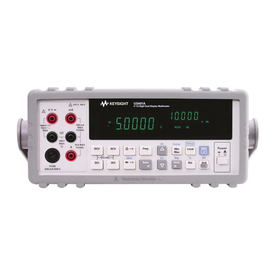
Keysight U3401A User And Service Manual (99 pages)
4 1/2 Digit Dual Display Multimeter
Brand:
Keysight
| Category:
Multimeter
| Size: 2 MB
Table of Contents
Declaration of Conformity
2
Safety Information
2
Safety Symbols
3
General Safety Information
4
Environmental Conditions
6
Regulatory Markings
7
Waste Electrical and Electronic Equipment (WEEE) Directive 2002/96/EC
8
Product Category
8
Sales and Technical Support
8
Table of Contents
9
1 Getting Started
17
Introducing the Keysight U3401A Dual Display Multimeter
18
Checking the Shipping Contents
19
Connecting Power to the Instrument
20
Stacking the U3401A
21
Figure 1-1 Stacking the U3401A
21
Adjusting the Handle
22
Figure 1-2 Type of Handle Position
22
Figure 1-3 Attaching and Detaching the Handle
22
Product at a Glance
23
Product Dimensions
23
Figure 1-4 U3401A Dimensions
23
The Front Panel at a Glance
24
Figure 1-5 Front Panel
24
The Display at a Glance
25
Figure 1-6 VFD Full Display with All Segments Illuminated
25
Table 1-1 Display Annunciators
26
The Keypad at a Glance
28
Figure 1-7 Keypad
28
Table 1-2 Keypad Functions
29
The Terminals at a Glance
31
Figure 1-8 Input Terminals
31
Table 1-3 Input Terminal for Different Functions
32
The Rear Panel at a Glance
33
Figure 1-9 Rear Panel
33
Making Measurements
34
Performing Voltage Measurements
35
Figure 1-10 ACV Terminal Connection and Display
35
Figure 1-11 DCV Terminal Connection and Display
36
Performing Current Measurements
37
Figure 1-12 ACI RMS or DCI (Ma) Terminal Connection and
37
Figure 1-13 ACI RMS or DCI (10A) Terminal Connection and
38
Performing Frequency Measurements
39
Figure 1-14 Frequency Terminal Connection and Display
39
Performing Resistance/Continuity Measurements
40
Figure 1-15 Resistance /Continuity Terminal Connection and
40
Performing Diode and Continuity Test
41
Figure 1-16 Forward-Biased Diode/Continuity Test Terminal Connection and Display
42
Figure 1-17 Reverse-Biased Diode/Continuity Terminal Connection and Display
42
Selecting a Range
43
2 Operations and Features
46
Operating Math Functions
46
Table 2-1 Math Operations for Different Measurement Functions
46
Dbm
47
Figure 2-1 Typical Dbm Operation Display
47
Figure 2-2 Typical Rel Operation Display
48
Rel
48
Figure 2-3 Typical Max Operation Display
49
Figure 2-4 Typical Min Operation Display
49
Minmax
49
Comp
51
Figure 2-5 Typical Comp Operation Display
51
Figure 2-6 Typical Hold Operation Display
53
Hold
53
Figure 2-7 Typical Refresh Hold Operation Display
54
Figure 2-8 Typical Percentage (%) Operation Display
55
Percentage (%)
55
Using the Secondary Display
57
Figure 2-9 Secondary Display
57
Using the Setup Menu
59
Changing the Configurable Settings
60
Figure 2-10 Typical Trigger Mode Display
61
Trigger Mode
61
3 Application Tutorial
63
Applications for Using Dual Display
64
Dual Display Operation Examples
65
Measure DC Voltage and AC Ripple on a Rectification Circuit
65
Figure 3-1 Connection Terminal When Measuring DC Voltage and AC Ripple
65
Measure AC and DC Current on a Rectification Circuit
66
Measure AC Voltage and Frequency on an AC Circuit
67
Measure Resistance
68
Measure True RMS AC + DC
69
4 Performance Test
71
Calibration Overview
72
Keysight Technologies Calibration Services
72
Calibration Interval
72
Performance Test Calibration Overview
72
Recommended Test Equipment
73
Table 4-1 Recommended Test Equipments
73
Test Considerations
74
Performance Verification Tests Overview
75
Performance Verification Tests
75
Table 4-2 DC Voltage Verification Test
76
Input Terminals
76
Table 4-3 DC Current Verification Test
77
Resistance Verification Test
78
Table 4-4 2-Wire Ω Verification Test
78
Ac Voltage Verification Test
80
Ac Current Verification Test
81
5 Disassembly and Repair
84
Operating Checklist
84
Types of Service Available
85
Repackaging for Shipment
86
Cleaning
86
To Replace the Power Line Fuse
87
To Replace a Current Input Fuse
88
Electrostatic Discharge (ESD) Precautions
88
Table 5-2 Type of Current Input Fuse
88
Mechanical Disassembly
89
Replaceable Parts
95
To Order Replaceable Parts
95
Specifications
97
Advertisement
Advertisement
Related Products
Keysight U3606B
Keysight U3606A
Keysight U1241B
Keysight U1242B
Keysight U1271A
Keysight U1231A
Keysight U1233A
Keysight U1253B
Keysight U1252
Keysight U1281A
Keysight Categories
Measuring Instruments
Test Equipment
Multimeter
Portable Generator
Power Supply
More Keysight Manuals
Login
Sign In
OR
Sign in with Facebook
Sign in with Google
Upload manual
Upload from disk
Upload from URL