Table of Contents
Advertisement
Quick Links
Advertisement
Table of Contents

Related Manuals for Keysight U3606A


Summary of Contents for Keysight U3606A
- Page 1 Keysight U3606A Multimeter|DC Power Supply User’s and Service Guide...
-
Page 3: Restricted Rights Legend
1400 Fountaingrove Parkway performance of this document or of Santa Rosa, CA 95403 any information contained herein. Should Keysight and the user have a separate written agreement with WA R N I N G warranty terms covering the material in this document that conflict with... -
Page 4: Safety Symbols
Out position of a bi-stable push control Frame or chassis terminal In position of a bi-stable push control CAT II Equipotentiality Category II 300 V overvoltage protection 300 V Equipment protected throughout by double insulation or reinforced insulation U3606A User’s and Service Guide... - Page 5 • Always use dry cloth to clean the device. Do not use ethyl alcohol or any other volatile liquid to clean the device. • Do not permit any blockage of the ventilation holes of the device. U3606A User’s and Service Guide...
-
Page 6: Environmental Conditions
Storage temperature –40 °C to 70 °C Relative humidity Up to 80% at 30 °C RH (non-condensing) The U3606A Multimeter|DC Power Supply complies with the following safety and N O T E EMC requirements: • IEC 61010-1:2001/EN61010-1:2001 (2nd Edition) • Canada: CAN/CSA-C22.2 No. 61010-1-04 •... - Page 7 Cet appareil ISM est confomre a la this electrical or electronic product in norme NMB-001 du Canada. domestic household waste. The CSA mark is a registered trademark of the Canadian Standards Association. U3606A User’s and Service Guide...
- Page 8 “Monitoring and Control Instrument” product. The affixed product label is as shown below. Do not dispose in domestic household waste To return this unwanted instrument, contact your nearest Keysight Technologies, or visit: www.keysight.com/environment/product for more information. U3606A User’s and Service Guide...
-
Page 9: In This Guide
In This Guide… Getting Started This chapter prepares the U3606A Multimeter|DC Power Supply for use, and contains a brief description of the instrument front panel, display, keypad, terminals, and rear panel. Digital Multimeter Operation This chapter contains detailed information on how to take measurements using the U3606A Multimeter|DC Power Supply. - Page 10 Characteristics and Specifications This chapter specifies the characteristics, environmental conditions, and specifications of the U3606A. List of Error Messages The U3606A error messages are summarized in this chapter. U3606A User’s and Service Guide...
- Page 11 The Declaration of Conformity (DoC) for this instrument is available on the Web site. You can search the DoC by its product model or description. http://regulations.products.keysight.com/DoC/search.htm If you are unable to search for the respective DoC, please contact your N O T E local Keysight representative. U3606A User’s and Service Guide...
- Page 12 U3606A User’s and Service Guide...
- Page 13 The rear panel at a glance Digital Multimeter Operation Making Measurements Performing voltage measurements Performing current measurements Performing resistance (2-wire) measurements Performing low-resistance (4-wire) measurements Performing frequency, pulse width, and duty cycle measurements Performing capacitance measurements Performing continuity tests U3606A User’s and Service Guide...
- Page 14 Constant voltage (CV) mode Constant current (CC) mode Protection Functions Overvoltage protection (OVP) Overcurrent protection (OCP) Overvoltage limit (OV) Overcurrent limit (OC) Square-wave Output Sweep Functions Ramp signal Scan signal Selecting a Range Enabling the Output U3606A User’s and Service Guide...
- Page 15 Storing and Recalling Instrument States Storing a state Recalling a stored state Remote Operation Configuring and connecting the GPIB interface Configuring and connecting the USB interface SCPI commands Verification and Performance Tests Recommended Test Equipment General measurement techniques U3606A User’s and Service Guide...
- Page 16 Calibration Overview Closed-case electronic calibration Keysight Technologies calibration services Calibration interval Adjustment is recommended Time required for calibration Recommended Test Equipment Calibration Process Calibration Security Unsecuring the instrument for calibration Changing the calibration security code U3606A User’s and Service Guide...
- Page 17 Finishing the adjustments Disassembly and Repair Operating Checklist Cleaning Fuse Replacement Electrostatic Discharge (ESD) Precautions Mechanical Disassembly General disassembly Replaceable Parts To Order Replaceable Parts Types of Services Available Repackaging for Shipment Characteristics and Specifications Product Characteristics U3606A User’s and Service Guide...
- Page 18 Supplementary characteristics DC Power Supply Specifications Safety considerations Specifications assumptions Performance specifications Supplementary characteristics List of Error Messages Error Messages Command errors Execution errors Internal errors Query errors Device specific errors Self-test errors Calibration errors U3606A User’s and Service Guide...
- Page 19 Figure 1-3 U3606A dimensions 10 Figure 1-4 U3606A front panel 11 Figure 1-5 VFD full display with all segments illuminated 12 Figure 1-6 U3606A keypad with both multimeter and source operations 15 Figure 1-7 U3606A connector terminals 20 Figure 1-8 U3606A rear panel 23...
- Page 20 Figure 5-10 Test setup for CC line and load regulation verification 153 Figure 5-11 Test setup for CC noise effect verification 153 Figure 5-12 Test setup for square-wave output verification 154 Figure 5-13 Load transient response time 169 Figure 6-1 SECUR pads location 188 U3606A User’s and Service Guide...
- Page 21 Constant voltage programming and readback accuracy verification test 164 Table 5-10 Constant voltage load effect verification test 165 Table 5-11 Constant voltage source effect verification test 166 Table 5-12 Constant current programming and readback accuracy verification U3606A User’s and Service Guide...
- Page 22 Table 9-3 List of internal errors 267 Table 9-4 List of query errors 267 Table 9-5 List of device specific errors 267 Table 9-6 List of self-test errors 268 Table 9-7 List of calibration errors 269 U3606A User’s and Service Guide...
- Page 23 The keypad at a glance 14 The terminals at a glance 19 The rear panel at a glance 22 This chapter prepares the U3606A Multimeter|DC Power Supply for use, and contains a brief description of the instrument front panel, display, keypad, terminals, and rear panel.
-
Page 24: Introduction
(excand independently, providing an efficient, convenient, and affordable testing solution. The U3606A has the dimensions of 2½U (rack unit) high, and provides the flexibility for bench or rack- mounted use. The front panel controls allow you to set the measurement parameters, mathematical operations, output parameters, protection features, and instrument settings. -
Page 25: Output Features
• User calibration from front panel and remote interface — software calibration, no internal physical adjustments • Sixteen storage locations for user- defined operating states • Portable, rugged case with non- skid feet • Kensington security slot — anti- theft system U3606A User’s and Service Guide... -
Page 26: Initial Inspection
Certificate of Calibration Keep the original packaging in case the U3606A has to be returned to Keysight in the future. If you return the U3606A for service, attach a tag identifying the owner and model number. Also, include a brief description of the problem. -
Page 27: Connecting Power To The Instrument
“Operating Checklist” on page 222). If self- test is successful, the U3606A goes into normal operation. The U3606A powers up in the following modes when turned on for the first time: • DC voltage measurement function with autoranging enabled, and •... -
Page 28: Adjusting The Handle
To adjust the handle, grasp the handle by the sides and pull outward. Then, rotate the handle to the desired position. The various positions available are illustrated below. Bench-top viewing positions Carrying position Figure 1-1 U3606A handle adjustments U3606A User’s and Service Guide... -
Page 29: To Rack Mount The Instrument
To Rack Mount the Instrument To Rack Mount the Instrument You can mount the U3606A in a standard 19- inch rack cabinet using one of the three optional kits available. Instructions and mounting hardware are included with each rack- mounting kit. Any Keysight Technologies instrument of the same size can be rack- mounted beside the U3606A Multimeter|DC Power Supply. -
Page 30: Stacking The Instrument
Stacking the Instrument Stacking the Instrument If you have purchased more than one unit of the U3606A Multimeter|DC Power Supply, you can stack the units on top of each other. The warning sign Stackable Direction located at the bottom side of the front and back rubber bumpers indicate the orientation of the rubber bumpers. -
Page 31: Product At A Glance
Getting Started Product at a Glance Product at a Glance Product dimensions 105 mm 329 mm 255 mm Figure 1-3 U3606A dimensions U3606A User’s and Service Guide... -
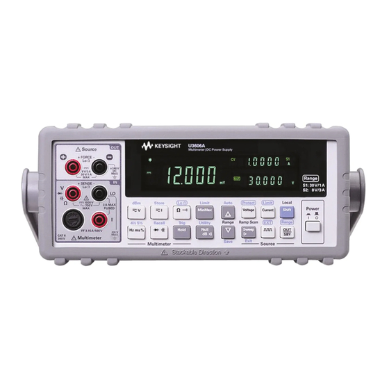
Page 32: The Front Panel At A Glance
Getting Started Product at a Glance The front panel at a glance Figure 1-4 U3606A front panel Item Description Positive (FORCE +) and negative (FORCE –) connector terminals for Source terminals source operation and 4-wire low-resistance measurement. Displays the instrument settings and readings. See “The display at a... -
Page 33: The Display At A Glance
Figure 1-5 VFD full display with all segments illuminated To view the full display (with all segments illuminated), press and hold Hold while powering- on the U3606A. After you are done viewing the full display, press Hold again to resume normal operation. - Page 34 Output range S2 selected — 8 V/3 A Voltage unit: V for constant voltage mode Current unit: A for constant current mode Frequency unit: Hz for square-wave output Data logging in progress (feature not applicable with the U3606A) U3606A User’s and Service Guide...
-
Page 35: U3606A User's And Service Guide
Getting Started Product at a Glance Table 1-1 U3606A display annunciators (continued) Annunciator Description Store Store instrument state selected Recall Recall instrument state selected Ramp Ramp signal output selected Scan Scan signal output selected Error One or more errors available in the error queue... -
Page 36: The Keypad At A Glance
Product at a Glance The keypad at a glance Figure 1-6 U3606A keypad with both multimeter and source operations The operation of each key is shown below. Pressing a key changes the current operation, illuminates a related annunciator on the display, and generates a key- click sound (a beep). -
Page 37: U3606A User's And Service Guide
Table 1-2 U3606A keypad functions Description System related operation Push Power to turn on or turn off the U3606A Multimeter|DC Power Supply. • Press Shift to perform a shifted function. See “Using the Shift key” on page 14 for more information. - Page 38 Getting Started Product at a Glance Table 1-2 U3606A keypad functions (continued) Description Press Shift > Recall to recall a previously stored instrument state. See “Recalling a stored state” on page 133 for more information. Multimeter operation Press to cycle between the DC, AC, and AC+DC voltage measurement functions. See “Performing voltage measurements”...
-
Page 39: U3606A User's And Service Guide
Getting Started Product at a Glance Table 1-2 U3606A keypad functions (continued) Description Press MinMax to store statistical data for the current readings. See “MinMax” on page 62 for more information. Press Shift > Limit to enable the limit math operation. See “Limit”... - Page 40 Getting Started Product at a Glance Table 1-2 U3606A keypad functions (continued) Description • Press to select the square-wave output. Use the directional keys to set the voltage amplitude. • Press again to cycle through the duty cycle, pulse width, and voltage amplitude settings.
-
Page 41: The Terminals At A Glance
[3] The continuity and diode test functions have a fixed 4½ digit resolution. Capacitance measurement is fixed to 3½ digit resolution. [4] The sweep functions can only be accessed when the U3606A is in constant voltage or constant current mode. You cannot access the sweep functions while the U3606A is in square-wave output mode. - Page 42 Low-resistance (4-wire) measurement 1000 V on all ranges, 3.15 A/250 V FF fuse DC current measurement AC current measurement 3.15 A/500 V FF fuse Frequency, duty cycle, and pulse width measurements via the current path U3606A User’s and Service Guide...
- Page 43 • Pulse width: 256 steps [1] Limited by range selected, S1 (30 V/1 A ) or S2 (8 V/3 A). See “Selecting a Range” on page 97 for more information on how to select a suitable range. U3606A User’s and Service Guide...
-
Page 44: The Rear Panel At A Glance
Getting Started Product at a Glance The rear panel at a glance Figure 1-8 U3606A rear panel Item Description Plug the power cord firmly into the power receptacle on the rear panel AC power connector of the instrument. See “Connecting Power to the Instrument” on page 5 for more information. -
Page 45: 2 Digital Multimeter Operation
Triggering the Multimeter 69 Front panel triggering 70 Remote interface triggering 71 This chapter contains detailed information on how to take measurements using the U3606A Multimeter|DC Power Supply. It also describes the various multimeter functions and features available in the U3606A. -
Page 46: Making Measurements
Making Measurements Making Measurements The following pages introduce the many types of measurements that you can make with the U3606A, and how to make the connections for each measurement. • Most basic measurements can be made using the instrument factory N O T E default settings. -
Page 47: Performing Voltage Measurements
(autoranging). To manually select a range, “Selecting a Range” on page 54 for more information. • The U3606A resolution is set to 5½ digits by default. To change the resolution, see “Setting the Resolution” on page 55 for more information. -
Page 48: Table 2-1 Dc Voltage Measurement Summary
< 0.3 A short circuit 2 Connect the red and black test leads to input terminals V (red) and LO (black) respectively as shown in Figure 2- 3 Probe the test points and read the display. U3606A User’s and Service Guide... -
Page 49: Table 2-2 Ac Voltage Measurement Summary
300% of range. Limited by maximum input. 2 Connect the red and black test leads to input terminals V (red) and LO (black) respectively as shown in Figure 2- 3 Probe the test points and read the display. U3606A User’s and Service Guide... - Page 50 Digital Multimeter Operation Making Measurements Measuring AC+DC voltage The U3606A Multimeter|DC Power Supply includes a true- rms multimeter that returns an accurate rms reading not only for sine waves, but also other AC signals such as square, triangle, and staircase waveforms without any DC offset.
-
Page 51: Performing Current Measurements
(autoranging). To manually select a range, “Selecting a Range” on page 54 for more information. • The U3606A resolution is set to 5½ digits by default. To change the resolution, see “Setting the Resolution” on page 55 for more information. -
Page 52: Table 2-3 Dc Current Measurement Summary
Protected with a 3.15 A/500 V, FF fuse 2 Connect the red and black test leads to input terminals I (red) and LO (black) respectively as shown in Figure 2- 3 Probe the test points and read the display. U3606A User’s and Service Guide... -
Page 53: Table 2-4 Ac Current Measurement Summary
300% of range. Limited by maximum input. 2 Connect the red and black test leads to input terminals I (red) and LO (black) respectively as shown in Figure 2- 3 Probe the test points and read the display. U3606A User’s and Service Guide... - Page 54 Digital Multimeter Operation Making Measurements Measuring AC+DC current The U3606A Multimeter|DC Power Supply includes a true- rms multimeter that returns an accurate rms reading not only for sine waves, but also other AC signals such as square, triangle, and staircase waveforms without any DC offset.
-
Page 55: Performing Resistance (2-Wire) Measurements
(autoranging). To manually select a range, see “Selecting a Range” on page 54 for more information. • The U3606A resolution is set to 5½ digits by default. To change the resolution, see “Setting the Resolution” on page 55 for more information. -
Page 56: Table 2-5 Resistance Measurement Summary
< 0.3 A short circuit 2 Connect the red and black test leads to input terminals (red) and LO (black) respectively as shown in Figure 2- 3 Probe the test points and read the display. U3606A User’s and Service Guide... -
Page 57: Performing Low-Resistance (4-Wire) Measurements
Disconnect circuit power and discharge all high-voltage capacitors C A U T I O N before measuring resistance or conductance, or testing circuit continuity, to avoid damaging the U3606A or the device under test. DC power supply functions are locked N O T E The DC power supply functions are locked when you select the low-resistance (Lo Ω) measurements. -
Page 58: Figure 2-4 Terminal Connections For 4-Wire Resistance Measurements
(autoranging). To manually select a range, see “Selecting a Range” on page 54 for more information. • The U3606A resolution is set to 5½ digits by default. To change the resolution, see “Setting the Resolution” on page 55 for more information. -
Page 59: Table 2-6 Low-Resistance Measurement Summary
Figure 2- 3 Connect the second red and black test leads to input terminals (SENSE +) and LO (SENSE –) respectively as shown in Figure 2- 4 Probe the test points and read the display. U3606A User’s and Service Guide... -
Page 60: Performing Frequency, Pulse Width, And Duty Cycle Measurements
(rms) current” on page 31) measurements first. Making the connections Connect the test leads as shown below: Frequency source Figure 2-5 Terminal connections for frequency, pulse width, and duty cycle measurements via the voltage path U3606A User’s and Service Guide... - Page 61 AC current measurements by default (autoranging). To manually select a range, see “Selecting a Range” on page 54 for more information. • The U3606A resolution is set to 5½ digits by default. To change the resolution, see “Setting the Resolution” on page 55 for more information.
-
Page 62: Table 2-7 Frequency Measurement (Voltage Path) Summary
< 0.3 A short circuit 2 Connect the red and black test leads to input terminals V (red) and LO (black) respectively as shown in Figure 2- 3 Probe the test points and read the display. U3606A User’s and Service Guide... - Page 63 Pulse width annunciator 3 Connect the red and black test leads to input terminals V (red) and LO (black) respectively as shown in Figure 2- 4 Probe the test points and read the display. U3606A User’s and Service Guide...
- Page 64 Duty cycle annunciator 3 Connect the red and black test leads to input terminals V (red) and LO (black) respectively as shown in Figure 2- 4 Probe the test points and read the display. U3606A User’s and Service Guide...
-
Page 65: Table 2-8 Frequency Measurement (Current Path) Summary
Protected with a 3.15 A/500 V, FF fuse 2 Connect the red and black test leads to input terminals I (red) and LO (black) respectively as shown in Figure 2- 3 Probe the test points and read the display. U3606A User’s and Service Guide... - Page 66 Pulse width annunciator 3 Connect the red and black test leads to input terminals I (red) and LO (black) respectively as shown in Figure 2- 4 Probe the test points and read the display. U3606A User’s and Service Guide...
- Page 67 Duty cycle annunciator 3 Connect the red and black test leads to input terminals I (red) and LO (black) respectively as shown in Figure 2- 4 Probe the test points and read the display. U3606A User’s and Service Guide...
-
Page 68: Performing Capacitance Measurements
Disconnect circuit power and discharge all high-voltage capacitors C A U T I O N before measuring capacitance to avoid damaging the U3606A or the device under test. To confirm that a capacitor has fully discharged, use the DC voltage measurement. See “Measuring DC voltage”... -
Page 69: Figure 2-7 Terminal Connections For Capacitance Measurements
Connect the test leads as shown below: – Capacitance Figure 2-7 Terminal connections for capacitance measurements • The U3606A will automatically select a suitable range for capacitance N O T E measurements by default (autoranging). To manually select a range, “Selecting a Range” on page 54 for more information. -
Page 70: Table 2-9 Capacitance Measurement Summary
< 0.3 A short circuit 2 Connect the red and black test leads to input terminals (red) and LO (black) respectively (refer to Figure 2- 7 on page 47). 3 Probe the test points and read the display. U3606A User’s and Service Guide... -
Page 71: Performing Continuity Tests
Disconnect circuit power and discharge all high-voltage capacitors C A U T I O N before measuring resistance or conductance, or testing circuit continuity, to avoid damaging the U3606A or the device under test. Making the connections Connect the test leads as shown below:... -
Page 72: Table 2-10 Continuity Function Summary
2 Connect the red and black test leads to input terminals (red) and LO (black) respectively as shown in Figure 2- 3 Probe the test points. The instrument beeps when the continuity measurement is less than or equal to the continuity threshold. U3606A User’s and Service Guide... -
Page 73: Performing Diode Tests
Performing diode tests Disconnect circuit power and discharge all high-voltage capacitors C A U T I O N before checking diodes to avoid damaging the U3606A or the device under test. Making the connections Connect the test leads as shown below: –... -
Page 74: Table 2-11 Diode Function Summary
(anode) of the diode and the black test lead to the negative terminal (cathode). Refer to Figure 2- 9 on page The cathode of a diode is indicated with a band. N O T E 4 Read the display. U3606A User’s and Service Guide... - Page 75 Digital Multimeter Operation Making Measurements The U3606A can display diode forward bias of up to approximately N O T E 1.2 V. The forward bias of a typical diode is within the range of 0.3 V to 0.8 V. 5 Reverse the probes and measure the voltage across the diode again...
-
Page 76: Selecting A Range
Digital Multimeter Operation Selecting a Range Selecting a Range You can allow the U3606A to automatically select the range using autoranging, or you can select a fixed range using manual ranging. Autoranging is convenient because the U3606A automatically selects the appropriate range for sensing and displaying each measurement. -
Page 77: Setting The Resolution
• Continuity and diode tests have a fixed 4½ digit display. • Capacitance measurements have a fixed 3½ digit display. Description Press Shift > 4½ 5½ to toggle between 4½ digit and 5½ digit mode. U3606A User’s and Service Guide... -
Page 78: Math Operations
• All math operations are automatically turned- off when changing measuring functions. • Range changing is allowed for all math operations. • For remote operation, refer to the CALCulate subsystem in the U3606A Programmer’s Reference. U3606A User’s and Service Guide... -
Page 79: Null
(nulls the test lead resistance), or across a desired null value circuit. The Null annunciator is illuminated and the null operation is enabled. Null annunciator Press Shift > Exit to exit the null mode. U3606A User’s and Service Guide... - Page 80 The display will then return to normal. 5 Press Shift > Exit to exit the edit mode without saving. • In resistance measurement, the U3606A will read a non-zero value N O T E even when the two test leads are in direct contact, because of the resistance of these leads.
-
Page 81: Dbm Measurements
The logarithmic dBm (decibels relative to 1 mW) scale is often used in RF signal measurements. The U3606A takes a measurement and calculates the power delivered to a reference resistance (typically 50 Ω, 75 Ω, or 600 Ω). -
Page 82: Db Measurements
Press Shift > dBm > dB to enable the dB operation. The first displayed reading is always precisely 00.000 dB. The dB annunciator is illuminated and the dB function is enabled. dB annunciator Press Shift > Exit to exit the dB mode. U3606A User’s and Service Guide... - Page 83 4 Press Shift > Save to save the changes. “donE” will be briefly displayed in the upper secondary display. The display will then return to normal. 5 Press Shift > Exit to exit the edit mode without saving. U3606A User’s and Service Guide...
-
Page 84: Minmax
Enabling the MinMax operation Press MinMax to enable the MinMax operation. The Max annunciator is illuminated and the U3606A begins accumulating various statistics about the readings being displayed. Max annunciator Press MinMax again to step through the maximum reading (the Max... - Page 85 Math Operations Each time a new minimum, maximum, or average value is stored, the instrument beeps once (if the beeper is enabled). The U3606A calculates the average of all readings and records the number of readings taken since the MinMax function was enabled.
-
Page 86: Limit
Instrument Preset (SYSTem:PRESet command), or when a measurement function is changed. Enabling the limit operation Press Shift > Limit to enable the limit operation. The Limit annunciator is illuminated and the limit function is enabled. Limit annunciator U3606A User’s and Service Guide... - Page 87 Each time the input value transitions from “PASS” to “HI” or from “PASS” to “LO”, or when transitioning directly from “HI” to “LO” or “LO” to “HI”, the instrument beeps once (if the beeper is enabled). Press Shift > Exit to exit the limit mode. U3606A User’s and Service Guide...
- Page 88 (HI) display. 7 Press Shift > Exit to exit the edit mode. The display will also return to normal after a few seconds of inactivity. U3606A User’s and Service Guide...
-
Page 89: Hold
131 for more information. In data hold mode, the reading is not updated even if the input signal value changes. The reading held will remain on the display until you exit the hold mode. U3606A User’s and Service Guide... - Page 90 Enabling the hold operation Press Hold to enable the hold operation. The Hold annunciator is illuminated and the hold function is enabled. Hold annunciator Press Hold again or Shift > Exit to exit the hold mode. U3606A User’s and Service Guide...
-
Page 91: Triggering The Multimeter
2 Specify the U3606A trigger source. The U3606A Multimeter|DC Power Supply will accept a software (bus) command or an immediate (continuous) trigger. 3 Ensure that the U3606A is ready to accept a trigger from the specified source (called the “wait- for- trigger” state). “Remote interface triggering” on page 71 for more information on the software (bus) or immediate triggering source. -
Page 92: Front Panel Triggering
Triggering the Multimeter Front panel triggering Single triggering The U3606A takes one reading each time you press Trig. The single trigger mode is available from the local interface only. N O T E Press Shift > Trig once to enable the single trigger mode. -
Page 93: Remote Interface Triggering
A trigger will not be accepted from the selected trigger source until the instrument is in the “wait- for- trigger” state. Refer to the U3606A Programmer’s Reference for the syntax and complete descriptions for these commands. Software (bus) triggering... - Page 94 IMMEdiate trigger is selected. • The INITiate command only initiates the measurement and needs a trigger (*TRG command) to make the actual measurement. Refer to the U3606A Programmer’s Reference for the syntax and complete descriptions for these commands. U3606A User’s and Service Guide...
-
Page 95: 3 Dc Power Supply Operation
U3606A Multimeter|DC Power Supply User’s and Service Guide DC Power Supply Operation Basic Operation 74 Constant voltage (CV) mode 74 Constant current (CC) mode 76 Protection Functions 78 Overvoltage protection (OVP) 78 Overcurrent protection (OCP) 81 Overvoltage limit (OV) 84... -
Page 96: Basic Operation
DC Power Supply Operation Basic Operation Basic Operation The U3606A has two basic operating modes: constant voltage and constant current mode. In constant voltage mode, the U3606A regulates the output voltage at the selected value, while the load current varies as required by the load. - Page 97 DC Power Supply Operation Basic Operation Supplying constant voltage 1 Press Voltage to select the constant voltage mode. When the U3606A is operating in constant voltage mode, the CV annunciator on the front panel is illuminated. CV annunciator 2 The output voltage can be programmed when the output is enabled (OUT) or disabled (SBY).
-
Page 98: Constant Current (Cc) Mode
DC Power Supply Operation Basic Operation Constant current (CC) mode Making the connections Connect the load as shown below: LOAD Figure 3-2 Constant current mode terminal connections U3606A User’s and Service Guide... - Page 99 DC Power Supply Operation Basic Operation Supplying constant current 1 Press Current to select the constant current mode. When the U3606A is operating in constant current mode, the CC annunciator on the front panel is illuminated. CC annunciator 2 The output current can be programmed when the output is enabled (OUT) or disabled (SBY).
-
Page 100: Protection Functions
Protection Functions Protection Functions Overvoltage protection (OVP) In constant current mode, the U3606A regulates the output current at the selected value, while the voltage varies as required by the load. The overvoltage protection protects against overvoltage conditions on the output. If the load attempts to draw more voltage than required, such that it exceeds the programmed protection value, the overvoltage protection circuit will protect the load by disabling the output. - Page 101 Then very gradually increase the output current using the directional keys until the OVP circuit trips. This will disable the U3606A output, cause the CC annunciator to flash, and the OV and Error annunciator to illuminate.
- Page 102 If the condition that caused the overvoltage shutdown is still present, the OVP circuit will turn the output off again. 1 When the OVP circuit trips, the U3606A will immediately prompt you to change the OVP trip level. Use the directional keys to select a higher OVP trip level and press Shift >...
-
Page 103: Overcurrent Protection (Ocp)
Protection Functions Overcurrent protection (OCP) In constant voltage mode, the U3606A regulates the output voltage at the selected value, while the load current varies as required by the load. The overcurrent protection will disable the output if the load effect exceeds the programmed protection value. - Page 104 Then very gradually increase the output voltage using the directional keys until the OCP circuit trips. This will disable the U3606A output, cause the CV annunciator to flash, and the OC and Error annunciator to illuminate.
- Page 105 If the condition that caused the overcurrent shutdown is still present, the OCP circuit will turn the output off again. 1 When the OCP circuit trips, the U3606A will immediately prompt you to change the OCP trip level. Use the directional keys to select a higher OCP trip level and press Shift >...
-
Page 106: Overvoltage Limit (Ov)
Setting the OV level The OV level can be programmed when the output is enabled (OUT) or disabled (SBY). Ensure that the U3606A is operating in constant current mode. (The CC annunciator is illuminated.) 1 Press Shift > Limit to enter the OV edit menu. - Page 107 • The OV value is limited by the range selected. Press Shift > Range to select an appropriate range. You can only select a range when the output is disabled (the SBY annunciator is illuminated). U3606A User’s and Service Guide...
-
Page 108: Overcurrent Limit (Oc)
Setting the OC level The OC level can be programmed when the output is enabled (OUT) or disabled (SBY). Ensure that the U3606A is operating in constant voltage mode. (The CV annunciator is illuminated.) 1 Press Shift > Limit to enter the OC edit menu. - Page 109 • The OC value is limited by the range selected. Press Shift > Range to select an appropriate range. You can only select a range when the output is disabled (the SBY annunciator is illuminated). U3606A User’s and Service Guide...
-
Page 110: Square-Wave Output
Selecting square-wave output 1 Press to select the square- wave mode. When the U3606A is operating in the square- wave mode, the square- wave annunciator ) on the front panel is illuminated. Square-wave annunciator 2 The default frequency is 600 Hz, as shown on the upper secondary display. - Page 111 • The square-wave amplitude is limited by the range selected. Press Shift > Range to select an appropriate range. You can only select a range when the output is disabled (the SBY annunciator is illuminated). U3606A User’s and Service Guide...
-
Page 112: Table 3-1 Available Frequencies For Square-Wave Output
(While still in the edit mode.) • Pressing Shift > Save will save the changes, and exit the edit mode. • Changing the square-wave frequency value will affect the square-wave duty cycle and pulse width values as they are inter-related. U3606A User’s and Service Guide... - Page 113 (While still in the edit mode.) • Pressing Shift > Save will save the changes, and exit the edit mode. • Changing the square-wave duty cycle value will affect the square-wave frequency and pulse width values as they are inter-related. U3606A User’s and Service Guide...
- Page 114 • Changing the square-wave pulse width value will affect the square-wave frequency and duty cycle values as they are inter-related. O U T When all the appropriate parameters have been set, press to generate S BY the square wave. U3606A User’s and Service Guide...
-
Page 115: Sweep Functions
DC Power Supply Operation Sweep Functions Sweep Functions The U3606A Multimeter|DC Power Supply is equipped with ramp and scan capability. Use the ramp function to generate a ramp signal with its end amplitude position and number of steps based on the preset input... - Page 116 5 Press to generate the ramp signal. S BY The typical ramp dwelling time per step in the U3606A is measured at N O T E 300 ms. A longer delay time should be expected if a high number of steps is programmed.
-
Page 117: Scan Signal
The scan dwell time also affects the first step at amplitude 0. An initial N O T E delay, the length of the preset scan dwell time, is expected for each complete scan signal sweep. U3606A User’s and Service Guide... - Page 118 4 Press Ramp Scan to select the scan function. Ensure that the Scan annunciator is shown on the display. Scan annunciator O U T 5 Press to generate the scan signal. S BY U3606A User’s and Service Guide...
-
Page 119: Selecting A Range
You select to either operate the U3606A in the 30 V/1 A range (S1) or the 8 V/3 A range (S2) for all output operations (CV mode, CC mode, square- wave output, and sweep functions). -
Page 120: Enabling The Output
O U T key controls turn the U3606A output on or off. S BY With the output off, adjustments can be made to the U3606A or the load without shutting off power to the instrument. O U T key can be pressed at any time to enable or disable the U3606A S BY output. -
Page 121: Remote Sensing
It has no effect in constant current mode. Because sensing is independent of other U3606A functions, it can be used regardless of how the U3606A is programmed. With remote sensing, voltage readback monitors the load voltage at the remote sense points. -
Page 122: Figure 3-3 Remote Sensing Connections
Rear output terminals Shielded two-wire cable LOAD Figure 3-3 Remote sensing connections Rear output terminals Short bar LOAD Short bar Figure 3-4 Local sensing connections U3606A User’s and Service Guide... - Page 123 Remove any metal shorting bars connected to the rear output terminals. 2 Loosen the two captive screws in the rear output terminal block with a Phillips screwdriver. 3 Gently pull the rear output terminal block out. U3606A User’s and Service Guide...
- Page 124 Do not use the shield as one of the sensing conductors. Ground the shield at the U3606A end only. The other end of the shield should be left unconnected. Observe the polarity when connecting the sensing leads to the load. You can connect the output leads to either one of the two + or –...
- Page 125 See “Connecting the load leads to the rear terminal block” on page 101 for the proper steps to connect the load leads from the rear terminal block to the load. U3606A User’s and Service Guide...
- Page 126 See “Constant voltage (CV) mode” on page 74 for more information. 5 Press Shift > EXT to enable remote sensing. When the U3606A is operating in remote sensing mode, the EXT annunciator on the front panel is illuminated. EXT annunciator...
- Page 127 8, “Characteristics and Specifications,” starting on page 241 applies at the output terminals of the U3606A. When remote sensing, add 5 mV to this specification for each 1 V drop between the positive sensing point (S+) and output terminals (+) due to the change in load current.
- Page 128 DC Power Supply Operation Remote Sensing U3606A User’s and Service Guide...
-
Page 129: 4 System Related Operation
Configuring and connecting the USB interface 136 SCPI commands 137 This chapter lists the various items and settings in the utility menu. This chapter also describes how to store and recall an instrument state with the U3606A Multimeter|DC Power Supply. -
Page 130: Using The Utility Menu
Press Shift > Save to save a setting. Press Shift > Exit to exit the edit mode without saving or to exit the utility menu. U3606A User’s and Service Guide... -
Page 131: Changing Configurable Settings
Shift > Save to save the setting. (Or press Shift > Exit to exit the edit mode without saving.) 6 Repeat step step 4, and step 5 for all items in the utility menu. 7 Press Shift > Exit to exit the utility menu. The U3606A returns to normal operation. U3606A User’s and Service Guide... - Page 132 Press to decrement the digit. When you are done editing, save the new value by pressing Shift > Save. (Or press Shift > Exit to exit the edit mode without saving.) U3606A User’s and Service Guide...
-
Page 133: Utility Menu Summary
• Set the beep driving frequency to “2400 Hz” or “3840 Hz”. • Set “OFF” to disable the beep tone. bEEP 2400 Hz 3840 Hz • See “Configuring the beeper” on page 117 for more information. U3606A User’s and Service Guide... - Page 134 NN.NNN V N.NNNN A NNNNN S • The ramp dwelling time will be fastest of output capability (typically ~300 ms per step). • See “Configuring the ramp signal parameters” on page 123 for more information. U3606A User’s and Service Guide...
- Page 135 The reading value will not be updated when the reading falls below the threshold value. • See “Enable refresh hold” on page 130 “Enable data hold” on page 131 for more information. U3606A User’s and Service Guide...
-
Page 136: Reading Error Messages
The following procedure shows you how to read error messages from the front panel. For remote interface operation, refer to the SYSTem:ERRor? command in the U3606A Programmer’s Reference. 1 To access the utility menu, press Shift > Utility. 2 The first utility menu item (Error) will be shown in the upper secondary display. -
Page 137: Reading The Program Code Revision
4 Press to cycle between the interface board (IOb), source board (Sb), and measurement board (Mb) program code revisions. 5 After reading the program code revisions, press Shift > Exit to exit the utility menu. U3606A User’s and Service Guide... -
Page 138: Adjusting The Display Brightness
For remote interface operation, refer to the MEMory:STATe:RECall:AUTO command in the U3606A Programmer’s Reference. 1 To access the utility menu, press Shift > Utility. 2 The first utility menu item (Error) will be shown in the upper secondary display. -
Page 139: Configuring The Beeper
Configuring the beeper Normally, the U3606A beeps whenever certain conditions are met (for example, the U3606A beeps when a stable reading is captured in reading hold mode). The beep driving frequency is set to “3840 Hz” by default, but may be disabled through the front panel. -
Page 140: Connecting To A Remote Interface
1 To access the utility menu, press Shift > Utility. 2 The first utility menu item (Error) will be shown in the upper secondary display. 3 Press until the menu item “IOb” is shown in the upper secondary display. U3606A User’s and Service Guide... - Page 141 Shift > Save to save or press Shift > Exit to exit the edit mode without saving. 8 Press Shift > Exit to exit the utility menu. “Remote Operation” on page 134 for more information on the N O T E available remote interface connections. U3606A User’s and Service Guide...
-
Page 142: Performing A Self-Test
“YES”. 5 Press Shift > Save to save. The instrument will automatically exit the utility menu and execute the self- test. 6 If the self- test is successful, the U3606A will return to normal operation. U3606A User’s and Service Guide... -
Page 143: Selecting A Dbm Reference Resistance Value
5 After selecting an appropriate dBm reference resistance value, press Shift > Save to save or press Shift > Exit to exit the edit mode without saving. 6 Press Shift > Exit to exit the utility menu. U3606A User’s and Service Guide... -
Page 144: Setting The Output Protection State
“triP Sby” is shown in the secondary display as shown in the figure below. 4 Press to switch between “YES” and “no”. Select “YES” to enable the output protection state or “no” to disable the output protection state. U3606A User’s and Service Guide... -
Page 145: Configuring The Ramp Signal Parameters
1 To access the utility menu, press Shift > Utility. 2 The first utility menu item (Error) will be shown in the upper secondary display. 3 Press until the menu item “rAMP” is shown in the upper secondary display. U3606A User’s and Service Guide... - Page 146 For example, a 15 V amplitude end position divided by 100 steps gives an increment of 0.15 V per step. • The ramp dwelling time selected will be fastest of the instrument output capability. (Typically ~300 ms per step.) U3606A User’s and Service Guide...
-
Page 147: Configuring The Scan Signal Parameters
“SCAn” is shown in the upper secondary display. 4 Press Voltage or Current if you wish to configure the scan signal parameters for CV or CC output. (The CV or CC annunciator illuminates respectively when selected.) U3606A User’s and Service Guide... - Page 148 9 After configuring the scan signal parameters, press Shift > Save to save or press Shift > Exit to exit the edit mode without saving. 10 Press Shift > Exit to exit the utility menu. U3606A User’s and Service Guide...
-
Page 149: Setting The Smooth Function
1 To access the utility menu, press Shift > Utility. 2 The first utility menu item (Error) will be shown in the upper secondary display. 3 Press until the menu item “SMoth” is shown in the upper secondary display. U3606A User’s and Service Guide... - Page 150 • You can also manually restart the smooth function by pressing MinMax for more than one second. • Setting the fluctuation count to 0.0% will disable the fluctuation count. It is recommended that the fluctuation count is enabled. U3606A User’s and Service Guide...
- Page 151 7 After setting the smooth function, press Shift > Save to save or press Shift > Exit to exit the edit mode without saving. 8 Press Shift > Exit to exit the utility menu. U3606A User’s and Service Guide...
-
Page 152: Enable Refresh Hold
6 After configuring the refresh hold variation, press Shift > Save to save or press Shift > Exit to exit the edit mode without saving. 7 Press Shift > Exit to exit the utility menu. U3606A User’s and Service Guide... -
Page 153: Enable Data Hold
• The threshold (nH) is not applicable in the data hold mode. 5 Press Shift > Save to save or press Shift > Exit to exit the edit mode without saving. 6 Press Shift > Exit to exit the utility menu. U3606A User’s and Service Guide... -
Page 154: Storing And Recalling Instrument States
The instrument automatically saves the complete instrument configuration to State 0 whenever a power- down event occurs. For remote operation, refer to the MEMory:STATe:RECall:AUTO, *SAV, and *RCL commands in the U3606A Programmer’s Reference. Storing a state To store an instrument state: 1 Press Shift >... -
Page 155: Recalling A Stored State
3 Press Recall or Shift > Save to recall the selected state. The upper secondary display briefly shows “donE” when the state is successfully recalled. 4 The instrument will then return to normal operation. Select state 00 to recall the instrument last power-down state. N O T E U3606A User’s and Service Guide... -
Page 156: Remote Operation
Remote Operation Remote Operation The U3606A is shipped with both a GPIB (IEEE- 488) interface and a USB 2.0 interface on the rear panel. Only one interface can be enabled at a time. The GPIB interface is selected by default when the U3606A is shipped from the factory. -
Page 157: Configuring And Connecting The Gpib Interface
GPIB address Each device on the GPIB interface must have a unique address. You can set the U3606A address to any value between 0 and 30. The current address is displayed on the secondary display at the bottom left. The address is set to “01”... -
Page 158: Configuring And Connecting The Usb Interface
USB/LAN/GPIB Interfaces Connectivity Guide, located in the Keysight Automation-Ready CD-ROM, which is shipped with your instrument. • This CD includes the Keysight IO Libraries Suite and the Keysight Connection Expert application. For more information about Keysight's I/O connectivity software, visit www.keysight.com/find/iolib. -
Page 159: Scpi Commands
The U3606A complies with the syntax rules and conventions of SCPI (Standard Commands for Programmable Instruments). For a complete discussion of all the U3606A SCPI syntax available, refer to N O T E the U3606A Programmer’s Reference. This document is provided on the U3606A Product Reference CD-ROM that came with your instrument. - Page 160 System Related Operation Remote Operation U3606A User’s and Service Guide...
-
Page 161: 5 Verification And Performance Tests
U3606A Multimeter|DC Power Supply User’s and Service Guide Verification and Performance Tests Recommended Test Equipment 140 General measurement techniques 143 Using an electronic load 143 Connecting the current monitoring resistor 144 Test Considerations 145 Input Connections 146 Zero offset verification test setup 146... -
Page 162: Recommended Test Equipment
8½ digit resolution and readback Digital multimeter Keysight 3458A 8½ digit resolution Constant voltage • Voltage range: 30 V load effect (load Electronic load Keysight 6060B • Current range: 5 A regulation) • Open and short switches U3606A User’s and Service Guide... - Page 163 • Open and short switches Digital multimeter Keysight 3458A 8½ digit resolution Constant current programming • 0.01 Ω ± 0.1% Current monitoring ISOTEK Co. model and readback resistor (shunt) • TCR less than 20 ppm/°C U3606A User’s and Service Guide...
- Page 164 DSO8064A or Oscilloscope • Bandwidth limit: 20 MHz Infiniium • Probe: 1:1 with RF tip; 10:1 with RF tip for > 50 V equivalent R&S URE3 or RMS voltmeter 20 Hz to 20 MHz equivalent U3606A User’s and Service Guide...
-
Page 165: General Measurement Techniques
Substitution of the electronic load requires minor changes to the test procedures in this chapter. U3606A User’s and Service Guide... -
Page 166: Connecting The Current Monitoring Resistor
Connect the current monitoring leads inside the load- lead connections directly at the monitoring points on the resistor element. U3606A User’s and Service Guide... -
Page 167: Test Considerations
“0” output is correct. You will need to set the offset for each range of the measuring function being verified. [1] 120-minute warm-up period for instrument adjustments (calibration). See Chapter 6, “Calibration Procedures,” starting on page 177 for more information on the calibration procedures. U3606A User’s and Service Guide... -
Page 168: Input Connections
Shielded, twisted- pair PTFE interconnecting cables of minimum length are recommended between the calibrator and the U3606A. Cable shields should be earth ground referenced. This configuration is recommended for optimal noises and settling time performance during calibration. -
Page 169: Gain Verification Test Setup
Gain verification test setup Calibrator Figure 5-2 Test setup for DC voltage, AC voltage, resistance, and capacitance gain verification Alternate connection path Calibrator Figure 5-3 Test setup for DC current and AC current gain verification U3606A User’s and Service Guide... -
Page 170: Output Verification Test Setup
Verification and Performance Tests Input Connections Function/Arbitrary waveform generator Figure 5-4 Test setup for frequency gain verification Output verification test setup Digital multimeter Figure 5-5 Test setup for CV programming and readback accuracy verification U3606A User’s and Service Guide... -
Page 171: Figure 5-6 Test Setup For Cv Load And Line Regulation Verification
Figure 5-6 Test setup for CV load and line regulation verification Fix resistive load Differential amplifier – – V Ω Oscilloscope termination Ω termination RMS voltmeter Figure 5-7 Test setup for CV noise effect verification U3606A User’s and Service Guide... -
Page 172: Figure 5-8 Test Setup For Load Transient Response Time Verification
Verification and Performance Tests Input Connections LOAD Electronic load Oscilloscope Figure 5-8 Test setup for load transient response time verification Current monitoring resistor Digital multimeter Figure 5-9 Test setup for CC programming and readback accuracy verification U3606A User’s and Service Guide... -
Page 173: Figure 5-10 Test Setup For Cc Line And Load Regulation Verification
Figure 5-10 Test setup for CC line and load regulation verification AC/DC converter TCP305 TCPA300 Differential amplifier – –V Fix resistive load Ω termination RMS voltmeter Figure 5-11 Test setup for CC noise effect verification U3606A User’s and Service Guide... -
Page 174: Figure 5-12 Test Setup For Square-Wave Output Verification
Verification and Performance Tests Input Connections Oscilloscope Universal frequency counter Alternate path for square-wave frequency output verification Figure 5-12 Test setup for square-wave output verification U3606A User’s and Service Guide... -
Page 175: Verification And Performance Tests Overview
Additional Verification Tests. Tests are not performed with every calibration. Perform these tests to verify additional specifications or functions of the instrument. U3606A User’s and Service Guide... -
Page 176: Self-Test
Read the errors using the utility menu (see “Reading error messages” on page 114), or use the SYSTem:ERRor? query from the remote interface (see the U3606A Programmer’s Reference). A list of the possible self- test errors is given on page 266. -
Page 177: Performance Verification Tests
Note that resistance measurements use the Null math function (Null N O T E reading taken with test leads connected together) to eliminate test lead resistance. See “Null” on page 57 for more information on the Null math function. U3606A User’s and Service Guide... -
Page 178: Table 5-2 Zero Offset Verification Test
10 kΩ ±0.0005 kΩ Resistance 100 kΩ ±0.005 kΩ 1 MΩ ±0.00005 MΩ 10 MΩ ±0.0005 MΩ 100 MΩ ±0.005 MΩ 10 mA ±0.0015 mA 100 mA ±0.005 mA Open DC current ±0.00007 A ±0.00021 A U3606A User’s and Service Guide... -
Page 179: Gain Verification Test
±0.003 V 100 V 100 V ±0.03 V 1000 V 1000 V ±0.3 V Set the calibrator output to 0 V before disconnecting from the C A U T I O N instrument input terminals. U3606A User’s and Service Guide... -
Page 180: Table 5-4 Dc Current Gain Verification Test
3 Select each range in the order shown below. Provide the indicated input voltage and frequency. Compare the measurement results to the appropriate test limits shown in Table 5- 5. (Be certain to allow for appropriate source settling when using the Fluke 5520A.) U3606A User’s and Service Guide... -
Page 181: Table 5-5 Ac Voltage Gain Verification Test
3 Select each range in the order shown below. Provide the indicated input current and frequency. Compare the measurement results to the appropriate test limits shown in Table 5- 6. (Be certain to allow for appropriate source settling when using the Fluke 5520A.) U3606A User’s and Service Guide... -
Page 182: Table 5-6 Ac Current Gain Verification Test
Error from nominal 1 year 100 Ω 100 Ω ±0.058 Ω 1 kΩ 1 kΩ ±0.00055 kΩ 10 kΩ 10 kΩ ±0.0055 kΩ 100 kΩ 100 kΩ ±0.055 kΩ 1 MΩ 1 MΩ ±0.00065 MΩ U3606A User’s and Service Guide... -
Page 183: Table 5-8 Frequency Gain Verification Test
8. (Be certain to allow for appropriate source settling when using the Fluke 5520A.) Table 5-8 Frequency gain verification test Error from Input frequency Input voltage Range nominal 1 year 1 kHz 100 kHz ±0.0032 kHz U3606A User’s and Service Guide... -
Page 184: Output Verification Test
You should consider programming the U3606A over the remote interface N O T E for this test to avoid round off errors. See the U3606A Programmer’s Reference for more information on remote interface programming. CV programming and readback accuracy This test verifies that the constant voltage programming and readback accuracy are within published specifications. -
Page 185: Table 5-10 Constant Voltage Load Effect Verification Test
149). 5 Operate the electronic load in constant resistance mode, and set its resistance to 30 Ω . Ensure that the U3606A is operating within the specified limit and protection values. If not, adjust the electronic load by increasing the resistance so that the current drops slightly until the U3606A is operating within the specified limit and protection values. -
Page 186: Table 5-11 Constant Voltage Source Effect Verification Test
149). 6 Operate the electronic load in constant resistance mode, and set its resistance to 30 Ω . Ensure that the U3606A is operating within the specified limit and protection values. If not, adjust the electronic load by increasing the resistance so that the current drops slightly until the U3606A is operating within the specified limit and protection values. - Page 187 Set the low pass filter to 1 MHz bandwidth limit to filter out input signals containing higher frequencies. vi Set to the zero precision voltage generator. vii Set the input impedance to 1 MΩ . U3606A User’s and Service Guide...
- Page 188 2 Turn on the instrument. Press Voltage to select the constant voltage mode. Ensure that the S1 (30 V/1 A) range is selected (the S1 annunciator is illuminated). Press Shift > Range again if it is not. U3606A User’s and Service Guide...
-
Page 189: Figure 5-13 Load Transient Response Time
Note that the pulse width (t – t ) of the transients at 50 mV from the base line should be no more than 450 ms for the output. Figure 5-13 Load transient response time U3606A User’s and Service Guide... -
Page 190: Test
3 Set the output current to the full rated value (3 A for S2 range) and voltage to full scale. 4 Connect an additional electronic load across the front panel (red) (black) output terminals (see Figure 5- 10 on page 151). U3606A User’s and Service Guide... -
Page 191: Table 5-13 Constant Current Load Effect Verification Test
Performance Verification Tests 5 Operate the electronic load in constant resistance mode, and set its resistance to 2.5 Ω . Ensure that the U3606A is operating within the specified limit and protection values. If not, adjust the electronic load by reducing the resistance so that the voltage drops slightly until the U3606A is operating within the specified limit and protection values. -
Page 192: Table 5-14 Constant Current Source Effect Verification Test
Performance Verification Tests 6 Operate the electronic load in constant resistance mode, and set its resistance to 2.5 Ω . Ensure that the U3606A is operating within the specified limit and protection values. If not, adjust the electronic load by reducing the resistance so that the voltage drops slightly until the U3606A is operating within the specified limit and protection values. - Page 193 9 Obtain the maximum rms current measurement as indicated in the RMS voltmeter. Divide the value by 10 and then multiply by 5 to get the constant current rms noise measurement. The result should not exceed 0.001 A U3606A User’s and Service Guide...
-
Page 194: Additional Verification Tests
1 nF 1 nF ±0.028 nF 10 nF 10 nF ±0.15 nF 0.1 nF 100 nF ±0.501 nF 1 μF 1 μF ±0.015 μF 10 μF 10 μF ±0.15 μF 100 μF 100 μF ±1.5 μF U3606A User’s and Service Guide... -
Page 195: Optional Square-Wave Output Verification Test
You should consider programming the U3606A over a remote interface for N O T E this test to avoid round off errors. See the U3606A Programmer’s Reference for more information on remote interface programming. -
Page 196: Table 5-16 Square-Wave Amplitude Output Verification Test
3 Output each value in the order shown below. Record the output duty cycle reading on the oscilloscope. Compare the measurement results to the appropriate test limits shown in Table 5- U3606A User’s and Service Guide... -
Page 197: Table 5-18 Square-Wave Duty Cycle Output Verification Test
Table 5-18 Square-wave duty cycle output verification test Error from Output duty cycle Output amplitude Range nominal 1 year 50% @ 4800 Hz 30 V 30 V ±2.55 % 50% @ 4800 Hz ±2.55 % U3606A User’s and Service Guide... - Page 198 Verification and Performance Tests Additional Verification Tests U3606A User’s and Service Guide...
-
Page 199: 6 Calibration Procedures
U3606A Multimeter|DC Power Supply User’s and Service Guide Calibration Procedures Calibration Overview 178 Closed-case electronic calibration 178 Keysight Technologies calibration services 178 Calibration interval 179 Adjustment is recommended 179 Time required for calibration 179 Recommended Test Equipment 180 Calibration Process 181... -
Page 200: Calibration Overview
Keysight Technologies calibration services Keysight Technologies offers calibration services at competitive prices. When your instrument is due for calibration, contact your local Keysight Service Center for recalibration. See “Types of Services Available” page 239 for information on contacting Keysight. -
Page 201: Calibration Interval
Accuracy specifications are not valid beyond the 1- year calibration interval. Keysight does not recommend extending calibration intervals beyond 2 years for any application. This criteria for re- adjustment provides the best long- term stability. -
Page 202: Recommended Test Equipment
Resistance Calibrator Fluke 5520A < 20% of instrument 1 year specification Function/Arbitrary Frequency Keysight 33250A < 20% of instrument 1 year specification waveform generator Capacitance Calibrator Fluke 5520A < 20% of instrument 1 year specification U3606A User’s and Service Guide... -
Page 203: Calibration Process
6 Note the new security code (if it has been changed) and calibration count in the instrument maintenance records. Ensure that you quit the adjustment mode before powering off the N O T E instrument. U3606A User’s and Service Guide... -
Page 204: Calibration Security
If you forget your security code, you can disable the security feature by N O T E applying a temporary short inside the instrument as described in “Resetting the security code to the factory default” on page 185. U3606A User’s and Service Guide... - Page 205 2 The instrument will enter the calibration security code edit mode. “SECur” is displayed in the upper secondary display while the security code is displayed in the primary display. 3 Press to move the cursor to the right or to the left. U3606A User’s and Service Guide...
- Page 206 This command unsecures the instrument for calibration. The default security code is ATU3606A ATU3606A. The security code can only be changed when the instrument is unsecured. & CAL:SEC:CODE ON, ATU3606A This command secures the instrument from accidental or unauthorized adjustments. U3606A User’s and Service Guide...
-
Page 207: Changing The Calibration Security Code
“ABC1234”. & CAL:SEC:State ON, ABC1234 This command secures the instrument from accidental or unauthorized adjustments. See the CALIbration subsystem in the U3606A Programmer’s Reference for more information on the CALibration:SECurity:CODE <new_code> command. Resetting the security code to the factory default If you have forgotten the correct security code, you may follow the steps below to change the security code back to the factory default (ATU3606A). -
Page 208: Figure 6-1 Secur Pads Location
3 Solder a temporary short between the two exposed metal pads on the main printed circuit (PC) board assembly. The general location is shown Figure 6- 1. On the U3606A PC board, the pads are marked as “SECUR”. Figure 6-1 SECUR pads location... - Page 209 185. Be sure you record the new security code. Never calibrate the instrument while the case is open. Reassemble the C A U T I O N instrument before performing any calibration procedures. U3606A User’s and Service Guide...
-
Page 210: Calibration Count
2 Press MinMax to view the calibration count. The calibration count is displayed in the upper secondary display. 3 The instrument will return to the calibration operation after a few seconds of inactivity. U3606A User’s and Service Guide... -
Page 211: Calibration Message
& CAL:STR? This query returns the message currently stored in calibration memory (the quotes are also returned). $ "CAL: 27 Nov 2009" See the U3606A Programmer’s Reference for more information on the CALibration subsystem. U3606A User’s and Service Guide... -
Page 212: Using The Front Panel For Adjustments
Using the Front Panel for Adjustments Using the Front Panel for Adjustments This section describes the process used to perform adjustments from the front panel. Refer to the U3606A Programmer's Reference for remote interface commands. Selecting the adjustment mode Before performing any adjustments, you must first unsecure the instrument for calibration. -
Page 213: Aborting A Calibration In Progress
742 through 748. If this occurs, you should not use the instrument until a complete re-adjustment has been performed. A list of the possible calibration errors is given on page 267. U3606A User’s and Service Guide... -
Page 214: General Calibration Procedure
Using the Front Panel for Adjustments General calibration procedure The steps below shows how the calibration adjustments are performed. For detailed steps involved in each measurement or source function in the U3606A Multimeter|DC Power Supply, see the “Adjustments procedures” on page 195. - Page 215 Using the Front Panel for Adjustments 3 Set up the indicated reference input and apply this input to the correct terminals of the U3606A. For example: • If the required reference input is “Short”, use a shorting plug to short the two relevant terminals.
- Page 216 “Adjustments procedures” on page 195 and its respective submodule N O T E headings for a list of adjustment items and input adjustment values for each measurement and source function in the U3606A. U3606A User’s and Service Guide...
-
Page 217: Adjustments Procedures
(“CALib” is shown on the lower secondary display) with the upper secondary display showing “Short”. Connect the shorting plug between the V (red) and LO (black) front panel input terminals. Leave the current input I (red) open. U3606A User’s and Service Guide... - Page 218 “FAiL” and a calibration error number appearing in the upper secondary display. Correct the problem and repeat this procedure. 8 Perform the “Zero offset verification test” on page 155 to check the zero calibration results. U3606A User’s and Service Guide...
-
Page 219: Gain Adjustments
Never turn off the instrument during a gain adjustment. This may C A U T I O N cause the calibration memory for the present function to be lost. U3606A User’s and Service Guide... -
Page 220: Table 6-2 Valid Gain Adjustment Input Values
0.9 to 1.1 × full scale page 203 (2-wire) • 100 kΩ • 1 MΩ • 10 MΩ • 10 mA 0.9 to 1.1 × full scale DC current • 100 mA page 205 • 1000 mA U3606A User’s and Service Guide... - Page 221 4 Use to select the adjustment item. 5 Apply the input signal shown in the “Input” column of Table 6- Always complete tests in the same order as shown in Table 6-3. N O T E U3606A User’s and Service Guide...
-
Page 222: Table 6-3 Dc Voltage Gain Adjustment
–1 V 10.0000 V 10 V 100.000 V 100 V 1000.00 V 1000 V Set the calibrator output to 0 V before disconnecting from the C A U T I O N instrument input terminals. U3606A User’s and Service Guide... - Page 223 Correct the problem and repeat this procedure. 8 Repeat step 3 through step 7 for each gain adjustment point shown in Table 6- 9 Verify the AC voltage gain adjustments using the “AC voltage verification test” on page 158. U3606A User’s and Service Guide...
-
Page 224: Table 6-4 Ac Voltage Gain Adjustment
5 Apply the input signal shown in the “Input” column of Table 6- Always complete tests in the same order as shown in Table 6-5. N O T E 6 Enter the actual applied input (see “Entering adjustment values” on page 190). U3606A User’s and Service Guide... -
Page 225: Table 6-5 Frequency Gain Adjustment
3 Configure each adjustment item shown in Table 6- If the zero offset adjustment procedure has been recently performed prior N O T E to the resistance gain calibration procedure, the adjustment items “Short” and “OPEn” can be omitted. U3606A User’s and Service Guide... -
Page 226: Table 6-6 Resistance Gain Adjustment
Input terminals open (remove any test leads or OPEn shorting plugs from the input terminals) 10.0000 MΩ 10 MΩ 1.00000 MΩ 1 MΩ 100.000 kΩ 100 kΩ 10.0000 kΩ 10 kΩ U3606A User’s and Service Guide... - Page 227 The display “CALib” in the lower S BY secondary display starts flashing to indicate that the calibration is in progress. • Successful completion of the adjustment is indicated by a short beep and the primary display briefly showing “PASS”. U3606A User’s and Service Guide...
-
Page 228: Table 6-7 Dc Current Gain Adjustment
4 Use to select the adjustment item. 5 Apply the input signal shown in the “Input” column of Table 6- Always complete tests in the same order as shown in Table 6-8. N O T E U3606A User’s and Service Guide... -
Page 229: Table 6-8 Ac Current Gain Adjustment
2 The primary display will show the uncalibrated value and the upper secondary display will show the reference value of the adjustment item. 3 Configure each adjustment item shown in Table 6- U3606A User’s and Service Guide... -
Page 230: Table 6-9 Capacitance Gain Adjustment
172. Table 6-9 Capacitance gain adjustment Adjustment item Input capacitance Input terminals open (remove any test leads or OPEn shorting plugs from the input terminals) 0.400 nF 0.4 nF 1.000 nF 1 nF U3606A User’s and Service Guide... - Page 231 Table 6-9 Capacitance gain adjustment (continued) Adjustment item Input capacitance 10.00 nF 10 nF 100.0 nF 100 nF 1.000 μF 1 μF 10.00 μF 10 μF 100.0 μF 100 μF 1000 μF 1000 μF 10000 μF 10000 μF U3606A User’s and Service Guide...
-
Page 232: Output Adjustments
Output adjustments The instrument calculates and stores output corrections for each output level. The U3606A implements a closed loop output calibration procedure to its inherent dual function ability as a digital multimeter and a DC power supply. The output constant is computed from the calibration level set for the calibration command and from measurements made automatically during the adjustment procedure. - Page 233 The display “CALib” in the lower S BY secondary display starts flashing to indicate that the calibration is in progress. • Successful completion of the adjustment is indicated by a short beep and the primary display briefly showing “PASS”. U3606A User’s and Service Guide...
-
Page 234: Table 6-11 Constant Current Output Adjustment
30 Ω, 50 W load 9 Verify the constant current adjustments using the “CC programming and readback accuracy” on page 168. Table 6-11 Constant current output adjustment Range Adjustment item Output current OUt-L S2 (8 V/3 A) OUt-H U3606A User’s and Service Guide... - Page 235 3 The primary display will show the uncalibrated value and the upper secondary display will show the reference level of the adjustment item. 4 Configure each adjustment item shown in Table 6- 5 Use to select the adjustment item. U3606A User’s and Service Guide...
- Page 236 For adjustment item “LOAd”, connect an additional 30 Ω, 50 W load across the front panel (red) and (black) output terminals. Leave the connections from the output terminals ( ) to the input terminals (V and LO) intact. 30 Ω, 50 W load U3606A User’s and Service Guide...
-
Page 237: Table 6-12 Constant Voltage Output Adjustment
Ensure that the rear panel sense terminals (+S and –S) are shorted to the N O T E rear panel output (+ and –) terminals. See “Remote sensing connections” on page 100 for more information on how to connect the load leads. U3606A User’s and Service Guide... - Page 238 Calibration Procedures Adjustments procedures + S + – – –S 2 Press Shift > EXT to enable remote sensing. When the U3606A is operating in remote sensing mode, the EXT annunciator on the front panel is illuminated. 3 Perform step 2...
- Page 239 Ensure that the rear panel sense terminals (+S and –S) are shorted to the N O T E rear panel output (+ and –) terminals. See “Remote sensing connections” on page 100 for more information on how to connect the load leads. U3606A User’s and Service Guide...
- Page 240 Calibration Procedures Adjustments procedures + S + – – –S 2 Press Shift > EXT to enable remote sensing. When the U3606A is operating in remote sensing mode, the EXT annunciator on the front panel is illuminated. 3 Perform step 2...
-
Page 241: Finishing The Adjustments
3 Record the new calibration count (“Calibration Count” on page 188). 4 Press Shift > Exit or Shift + to exit the adjustment mode. 5 The instrument will be secured and returns to normal operation. U3606A User’s and Service Guide... - Page 242 Calibration Procedures Adjustments procedures U3606A User’s and Service Guide...
-
Page 243: 7 Disassembly And Repair
U3606A Multimeter|DC Power Supply User’s and Service Guide Disassembly and Repair Operating Checklist 222 Cleaning 223 Fuse Replacement 223 To replace the power line fuse 223 To replace the current input fuse 226 Electrostatic Discharge (ESD) Precautions 228 Mechanical Disassembly 229... -
Page 244: Operating Checklist
Disassembly and Repair Operating Checklist Operating Checklist Before returning your instrument to Keysight for service or repair, do a check on the following items: Is the instrument inoperative? Verify that the power cord is connected to the instrument and to the AC line power. -
Page 245: Cleaning
The power line fuse is located within the U3606A fuse- holder assembly on the rear panel. The U3606A is shipped from the factory with a power- line fuse installed. The supplied fuse is a time- lag, low- breaking, 2 A/250 V,... - Page 246 Disassembly and Repair Cleaning S/B 5×20 mm fuse, Keysight part number A02- 62- 25026- 2U. If you are certain that the fuse is faulty, replace it with one of the same size and rating. 1 Disconnect power cord. Using a flat blade screwdriver, gently pry open the fuse holder assembly as shown below.
- Page 247 2 Remove the fuse holder assembly from the rear panel. 3 Remove the faulty power line fuse and replace it with a new power line fuse in the fuse holder assembly. 4 Re- insert the fuse holder assembly into the rear panel. U3606A User’s and Service Guide...
- Page 248 The fuse is a 3.15 A/500 V F/B 6.3×32 mm fuse, Keysight part number A02- 62- 25657- 1U. If you are certain that the fuse is faulty, replace it with one of the same size and rating.
- Page 249 3 Remove the faulty current input fuse and replace a new current input fuse into the fuse holder assembly. 4 Re- insert the fuse holder assembly into the front panel. Turn the screwdriver clockwise to fasten the fuse holder assembly in place. U3606A User’s and Service Guide...
-
Page 250: Electrostatic Discharge (Esd) Precautions
• Minimize handling. • Keep replacement parts in original static- free packaging. • Remove all plastic, foam, vinyl, paper, and other static- generating materials from the immediate work area. • Use only anti- static solder suckers. U3606A User’s and Service Guide... -
Page 251: Mechanical Disassembly
General disassembly 1 Turn off the power. Remove all cables from the instrument. 2 Remove the carry handle. Rotate the handle upright and pull out from the sides of the instrument. U3606A User’s and Service Guide... - Page 252 3 Remove the instrument bumpers. Pull from a corner and stretch the bumpers off the instrument. 4 Remove the rear bezel. Loosen the two captive screws in the rear bezel and remove the rear bezel. U3606A User’s and Service Guide...
- Page 253 Disassembly and Repair Mechanical Disassembly 5 Remove the cover. Remove the screws in the bottom of the cover. 6 Slide the cover off the instrument. U3606A User’s and Service Guide...
- Page 254 Turn the instrument over and gently move the power switch push rod towards the front of the instrument to disengage it from the switch. Be careful not to twist or bend the push rod. b Disconnect the two ribbon cable connectors from the front panel. U3606A User’s and Service Guide...
- Page 255 Disconnect the individual wires from the top layer circuit board as shown below. 8 Remove the top layer circuit board. Loosen the four captive screws in the top layer circuit board and remove the top layer circuit board. Remove the protective metal sheet as well. U3606A User’s and Service Guide...
- Page 256 Disassembly and Repair Mechanical Disassembly 9 Disconnect the individual wires from the bottom layer circuit board as shown below. 10 Remove the two screws holding the front panel. U3606A User’s and Service Guide...
- Page 257 Mechanical Disassembly 11 You can now pry the side of the front panel from the chassis and remove it. Front panel disassembly 12 Loosen the two captive screws and remove the keypad and display assembly. U3606A User’s and Service Guide...
- Page 258 13 Remove the keypad and display assembly. The rubber keypad and VFD display assembly can now be pulled out from the plastic housing. 14 To reassemble all the modules again, just follow the disassembly procedure backwards. U3606A User’s and Service Guide...
-
Page 259: Replaceable Parts
Front panel fuse holder Fuse 3.15 A/500 V F/B 6.3 × 32 mm A02-62-25657-1U U3401-40001 Rubber bumper kit (front and rear) U3606-00200 Front panel assembly U3606-40004 Keypad U3606-45001 Carry handle U3606-60034 Shorting bar U3606-60035 External terminal block assembly U3606A User’s and Service Guide... -
Page 260: To Order Replaceable Parts
To order replaceable parts from Keysight, do the following: 1 Contact your nearest Keysight Sales Office or Service Center. 2 Identify the parts by the Keysight part number shown in the replaceable parts list. 3 Provide the instrument model number and serial number. -
Page 261: Types Of Services Available
• In the United States: (800) 829- 4444 • In Europe: 31 20 547 2111 • In Japan: 0120- 421- 345 • Or use our Web link for information on contacting Keysight worldwide: • www.keysight.com/find/assist • Or contact your Keysight Technologies representative. -
Page 262: Repackaging For Shipment
Repackaging for Shipment Repackaging for Shipment If the unit is to be shipped to Keysight for service or repair, be sure to: • Attach a tag to the unit identifying the owner and indicating the required service or repair. Include the model number and full serial number. -
Page 263: 8 Characteristics And Specifications
U3606A Multimeter|DC Power Supply User’s and Service Guide Characteristics and Specifications Product Characteristics 242 Digital Multimeter Specifications 244 Specification assumptions 244 DC specifications 244 AC specifications 247 Frequency specifications 248 Duty cycle and pulse width specifications 249 Operating specifications 250... -
Page 264: Product Characteristics
• Canada: CAN/CSA-C22.2 No. 61010-1-04 • USA: ANSI/UL 61010-1:2004 EMC COMPLIANCE Certified with: • IEC 61326-1:2005/EN61326-1:2006 • CISPR11:2003/EN55011:2007, Group 1 Class A • Canada: ICES/NMB-001:2004 • Australia/New Zealand: AS/NZS CISPR 11:2004 SHOCK AND VIBRATION Tested to IEC/EN 60068-2 U3606A User’s and Service Guide... - Page 265 • Please note that for the product, the warranty does not cover: • Damage from contamination • Normal wear and tear of mechanical components • Manuals or fuses CALIBRATION CYCLE One year WARM UP TIME 60 minutes U3606A User’s and Service Guide...
-
Page 266: Digital Multimeter Specifications
0.015 + 0.005 0.025 + 0.005 0.0020 + 0.0005 100.000 V 0.012 + 0.005 0.015 + 0.005 0.025 + 0.005 0.0015 + 0.0005 1000.00 V 0.012 + 0.005 0.015 + 0.005 0.025 + 0.005 0.0015 + 0.0005 U3606A User’s and Service Guide... - Page 267 0.25 + 0.03 Continuity 1.0000 kΩ 0.83 mA 0.04 + 0.005 0.04 + 0.005 0.05 + 0.005 0.0050+0.0005 Diode 1.0000 V 0.83 mA 0.04 + 0.005 0.04 + 0.005 0.05 + 0.005 0.0050 + 0.0005 U3606A User’s and Service Guide...
- Page 268 [3] Any current measurement greater than 500 mA will have a temporary thermo-effect. If you wish to measure a lower current or offset current immediately after a high current measurement, ensure that the U3606A has cooled down. [4] Specifications stated are for 2-wire resistance measurements using the Null math operation. Without Null, add a 0.2 Ω error.
-
Page 269: Ac Specifications
The specification of the AC+DC measurement will be the sum of the AC and DC accuracy. N O T E The frequency range will be from 50 Hz for 5½ digit resolution and 225 Hz for 4½ digit resolution. U3606A User’s and Service Guide... -
Page 270: Frequency Specifications
20 Hz to 100 kHz 100 kHz to 300 kHz 300 kHz to 1 MHz 100 mV 50 mV 50 mV 0.5 V 1.0 V 100 mV 120 mV 0.5 V 10 V 1.2 V U3606A User’s and Service Guide... -
Page 271: Duty Cycle And Pulse Width Specifications
[1] The range is calculated from {10 μs × frequency × 100%} to {[1 – (10 μs × frequency)] × 100%}. For example, a 1 kHz signal can be measured from 1% to 99%. [2] The positive or negative pulse width must be greater than 10 μs. The range of the pulse width is determined by the frequency of the signal. U3606A User’s and Service Guide... -
Page 272: Operating Specifications
[1] Reading rate of the A/D converter. [2] Number of measurements per second that can be read through USB using SCPI “READ?” command. [3] Number of measurements per second that can be read through GPIB using SCPI “READ?” command. U3606A User’s and Service Guide... -
Page 273: Supplementary Characteristics
Maximum 3.0 at full scale. Peak input: 300% of range. Limited by maximum input. Response time: Approximately 2.5 s when the displayed reading reaches 99.9% AC rms value of the tested input signal at the same range. U3606A User’s and Service Guide... - Page 274 [1] Any current measurement greater than 500 mA will have a temporary thermo-effect. If you wish to measure a smaller current or offset current measurement immediately after a high current measurement, ensure that the U3606A is cooled down. Resistance Measurement method: Two-wire, open-circuit voltage limited to <...
- Page 275 • Voltage path: 1000 V on all ranges, < 0.3 A short circuit Input protection: • Current path: Protected with a 3.15 A/500 V, FF fuse Maximum display counts (excluding frequency) 5½ digit: 120,000 4½ digit: 12,000 U3606A User’s and Service Guide...
- Page 276 LO lead 60 Hz ± 0.1% • 5½ digits: 65 dB NMRR (Normal Mode • 4½ digits: 0 dB Rejection Ratio) 50 Hz ± 0.1% • 5½ digits: 55 dB • 4½ digits: 0 dB U3606A User’s and Service Guide...
-
Page 277: Dc Power Supply Specifications
DC Power Supply Specifications Safety considerations The U3606A Multimeter|DC Power Supply is a safety class I instrument, which means it has a protective earth terminal. The terminal must be connected to an earth ground through a power source with a 3- wire ground receptacle. -
Page 278: Performance Specifications
±(% of output + offset) Current < 0.03% + 0.3 mA Voltage ±3 mV Line regulation Current ±1.5 mA Voltage 1 mV Programming resolution Current 0.1 mA Voltage 1 mV Readback resolution Current 0.1 mA U3606A User’s and Service Guide... -
Page 279: Supplementary Characteristics
• OVP/OCP: 8.8 V/3.3 A Temperature coefficient: • Voltage: 0.005% + 0.5 mV • Current: 0.02% +1 mA ± (% of output + offset) maximum change in output/readback per °C for 0 ºC to 18 ºC/28ºC to 55 ºC U3606A User’s and Service Guide... -
Page 280: Table 8-9 Square-Wave Output Specifications
Pulse width resolution Range/256 [1] Available frequencies: 0.5, 2, 5, 6, 10, 15, 25, 30, 40, 50, 60, 75, 80, 100, 120, 150, 200, 240, 300, 400, 480, 600, 800, 1200, 1600, 2400, 4800 (Hz) U3606A User’s and Service Guide... - Page 281 The pulse width accuracy (for frequency setting 4800 Hz and duty cycle setting 50%) is calculated as 0.2083 ms ±10.625 μs. • The rise and fall time is less than 25 μs. N O T E • The additional load regulation is 0.15 V/A. U3606A User’s and Service Guide...
-
Page 282: Table 8-10 Scan Output Specifications
1 step to 10000 steps 1 step to 10000 steps Dwelling time 300 ms (typical) per step 300 ms (typical) per step [1] Amplitude start position is fixed at 0 (V or A) by default. U3606A User’s and Service Guide... -
Page 283: 9 List Of Error Messages
User’s and Service Guide List of Error Messages Error Messages 262 Command errors 263 Execution errors 264 Internal errors 265 Query errors 265 Device specific errors 265 Self-test errors 266 Calibration errors 267 The U3606A error messages are summarized in this chapter. -
Page 284: Error Messages
The interface- specific and global error queues are cleared by the clear status (*CLS) command and when the instrument power is cycled. The error queue will not be cleared by a Factory Reset (*RST command) or an Instrument Preset (SYSTem:PRESet command). U3606A User’s and Service Guide... -
Page 285: Command Errors
Exponent too large –128 Numeric data not allowed –130 Suffix error –131 Invalid suffix –134 Suffix too long –138 Suffix not allowed –141 Invalid character data –144 Character data too long –148 Character data not allowed U3606A User’s and Service Guide... -
Page 286: Execution Errors
Error code Error message –200 Execution error –211 Trigger ignored –213 Init ignored –214 Trigger deadlock –220 Parameter error –221 Settings conflict –222 Data out of range –223 Too much data –230 Data corrupt or stale U3606A User’s and Service Guide... -
Page 287: Internal Errors
The following table shows the list of device specific errors. These errors set the Standard Event Status register bit 3. Table 9-5 List of device specific errors Error code Error message Voltage output over protection Current output over protection Voltage output over limit setting U3606A User’s and Service Guide... -
Page 288: Self-Test Errors
Source board failed I/O Processor Failed Self-Test Source Processor Failed Self-Test DC Path error AC Path attenuated error AC Path attenuated 10 error AC Path attenuated 100 or amplified 10 error Frequency measurement path failed U3606A User’s and Service Guide... -
Page 289: Calibration Errors
Cal signal frequency out of range No cal for this function or range EEPROM write failure Cal DCV offset out of range Cal DCI offset out of range Cal RES offset out of range Cal CAP offset out of range U3606A User’s and Service Guide... - Page 290 Cal checksum failed, RES corrections Cal checksum failed, ACV corrections Cal checksum failed, ACI corrections Cal checksum failed, FREQ correction Cal checksum failed, CAP corrections Source board failed on reading Source board failed on sense U3606A User’s and Service Guide...
- Page 291 List of Error Messages Error Messages U3606A User’s and Service Guide...
- Page 292 (tel) 0800 047 866 (fax) 0800 286 331 Other Asia Pacific Countries: (tel) (65) 6375 8100 (fax) (65) 6755 0042 Or visit Keysight World Wide Web at: www.keysight.com/find/assist Product specifications and descriptions in this document are subject to change without notice. Always refer to Keysight...
- Page 293 This information is subject to change without notice. © Keysight Technologies 2009 - 2017 Edition 11, November 2017 *U3606-90013* U3606-90013 www.keysight.com...
Need help?
Do you have a question about the U3606A and is the answer not in the manual?
Questions and answers