Table of Contents
Advertisement
Quick Links
Where a chimney is not blocked off completely it will cause the heater to cut out during use. If you are not sure that you have cut off the draw
100% from the chimney, we recommend covering the five banks of slots in the rear of the case and each bank at the top either side.
Electrical connections
Your appliance comes fitted with a plug that incorporates a 13A fuse. The replacement fuses must be 13A and ASTA approved. If the fuse cover is
lost the plug must not be used until a replacement cover, of the same colour, is obtained from an electrical retailer.
The appliance is fitted with a moulded plug, if it is necessary to cut off the plug for any reason, it must be discarded immediately with the
fuse removed. Under no circumstances should any attempt be made to reuse the plug, do not insert into any 13A socket as this could cause
a hazard. If the mains cable is damaged it must be replaced by the manufacturer or an authorised technical service centre.
WARNING THIS APPLIANCE MUST BE EARTHED
As the colours of the wires in the mains lead of this appliance may not correspond with the colour markings in your plug proceed as follows: -
The wire which is coloured green and yellow must be connected to the terminal in the plug which is marked with the letter E, or
coloured green or coloured green and yellow, or marked with the earth symbol
The wire which is coloured blue must be connected to the terminal in the plug which is marked with the letter N, or coloured
black.
The wire which is coloured brown must be connected to the terminal in the plug which is marked with the letter L, or coloured
red.
The Fire Front: is held on by four keyhole slot brackets, the corresponding screws are attached to the case. Lift the front to remove or replace it
back onto the fire. Fig.1
Using as a Hole in the Wall:
The inset dimensions for Hole in the Wall: depth 16cm, height 50cm and width 90.5cm. To prevent the fire from being pulled over it must be
secured into place. The height at which you may wish to fix the fire to the wall is up to you, though we recommend anywhere from 40-60cm from
the floor to the bottom of the fire. Four counter sunk holes will be visible at each corner, two on each side of the outer return. Place the fire into
the hole, mark off where the fixing holes are to be drilled. Remove fire and drill the holes. When this is done push the rawl plugs into the drilled
holes, lift and secure the fire into place. The front may be reapplied by lining up the keyhole slot brackets with their corresponding screws on the
fire and pushing it down. The screws may need to be adjusted to remove any slack and allow for a tight fit. *See fuel effect before fitting the
glass.
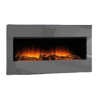
Flamerite Omni 2 Electric Floor Standing Fire Suite
INSTALLATION OF THE FIRE
The wires in the mains lead are coloured in accordance with the following code.
Green and yellow:
Blue:
Red:
Fig.1
IMPORTANT
EARTH
NEUTRAL
LIVE
Page 1 of 4
Advertisement
Table of Contents

Related Manuals for Flamerite Fires Omni 2


Summary of Contents for Flamerite Fires Omni 2
- Page 1 Flamerite Omni 2 Electric Floor Standing Fire Suite INSTALLATION OF THE FIRE Where a chimney is not blocked off completely it will cause the heater to cut out during use. If you are not sure that you have cut off the draw 100% from the chimney, we recommend covering the five banks of slots in the rear of the case and each bank at the top either side.
- Page 2 Using as a Hang on the Wall. The height at which you may wish to fix the fire to the wall is up to you, though we recommend anywhere from 40-60cm from the floor to the bottom of the fire. The rail should be fixed to the wall with the hooks facing upward and outward. Once the rail has been fixed in place, lift and hook the fire onto the rail.
- Page 3 OPERATING THE FIRE Controls: The fire can be operated either by manual or remote control. There is a main on/off switch top right of the fire, this is marked with I/O and will need to be switched to I (standby) to operate the fire. In the O position (off) you will be unable to operate the fire. Fig 4 Fig 5 1.
-
Page 4: Problem Solving
Changing battery in the remote Your remote has two batteries a CR2032 Lithium Battery and an alkaline MN21 12 Volt battery, replacements are available from Flamerite Fires stockists, most electrical or photographic stores. Ensure battery is disposed of safely. Do not dispose of in fire, do not swallow and keep away from children.
Need help?
Do you have a question about the Omni 2 and is the answer not in the manual?
Questions and answers