Table of Contents
Advertisement
KAR-18
TECHNICAL EDUCATION
KitchenAid Undercounter Refrigeration Suite
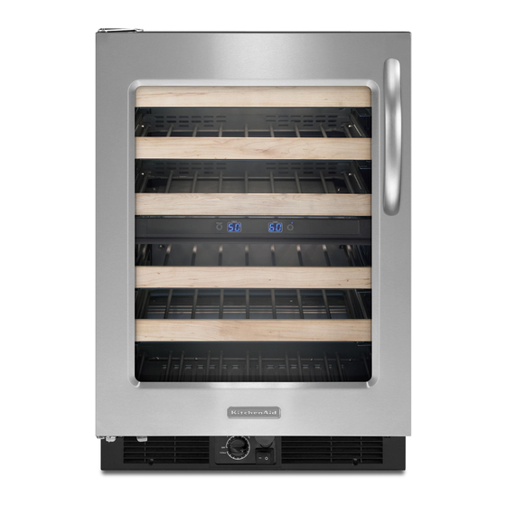
Wine Cellar
Models: KUWS24RSBS
KUWS24LSBS KUWS24RSSS
KUWO24RSBX KUWO24LSBX
Beverage Center
Models: KBCS24RSBS
KBCS24LSBS KBCS24RSSS
KBCO24RSBX KBCO24LSBX
Undercounter Refrigerator
Models: KURS24RSBS
KURS24LSBS KURS24RSSS
KURO24RSBX KURO24LSBX
JOB AID
4317405
Advertisement
Table of Contents


Need help?
Do you have a question about the KUWS24RSBS and is the answer not in the manual?
Questions and answers