Table of Contents
Advertisement
Quick Links
CONTENTS:
1. SAFETY PRECAUTIONS AND PROCEDURES .............................................................1
1.1.
Preliminary ............................................................................................................2
1.2.
During Use ............................................................................................................2
1.3.
After Use ...............................................................................................................2
1.4.
Definition of measuring (overvoltage) category .....................................................3
2. GENERAL DESCRIPTION ..............................................................................................3
3. PREPARATION FOR USE ..............................................................................................4
3.1.
Initial ......................................................................................................................4
3.2.
Supply Voltage ......................................................................................................4
3.3.
Calibration .............................................................................................................4
3.4.
Storage..................................................................................................................4
4. OPERATING INSTRUCTIONS........................................................................................5
4.1.
Instrument Description...........................................................................................5
4.1.1. Commands description.................................................................................................. 5
4.1.2. Alignment marks............................................................................................................ 5
4.1.3. Use of rubber test leads holster .................................................................................... 6
4.1.4. AUTO POWER OFF function ........................................................................................ 6
4.2.
Function key description........................................................................................6
4.2.1.
key: enable/disable backlight ................................................................................. 6
4.2.2. D-H key: HOLD function................................................................................................ 6
4.2.3. SELECT key: select according to function range indication on the clamp meter. ......... 6
4.2.4. R-H key: ........................................................................................................................ 6
4.3.
Description of Rotary Switch Function...................................................................7
4.3.1. AC/ DC Voltage measurement ...................................................................................... 7
4.3.2. AC/DC uA current measurement................................................................................... 8
4.3.3. AC Current measurement ............................................................................................. 8
4.3.4. Resistance measurement.............................................................................................. 9
4.3.5. Continuity Test ............................................................................................................ 10
4.3.6. Capacitance measurement ......................................................................................... 11
4.3.7. Temperature measurement......................................................................................... 12
5. MAINTENANCE ............................................................................................................12
5.1.
General information .............................................................................................12
5.2.
Battery replacement ............................................................................................12
5.3.
Fuse replacement................................................................................................13
5.4.
Cleaning ..............................................................................................................13
6. TECHNICAL SPECIFICATIONS ...................................................................................13
6.1.
Characteristics.....................................................................................................13
6.1.1. Safety .......................................................................................................................... 15
6.1.2. General data................................................................................................................ 15
6.2.
Environmental conditions ....................................................................................15
6.2.1. Climatic conditions ...................................................................................................... 15
6.2.2. EMC ............................................................................................................................ 15
6.3.
Accessories .........................................................................................................15
6.3.1. Standard accessories.................................................................................................. 15
Advertisement
Table of Contents

Related Manuals for Tenmars TM-1016


Summary of Contents for Tenmars TM-1016
- Page 1 CONTENTS: 1. SAFETY PRECAUTIONS AND PROCEDURES .............1 1.1. Preliminary ......................2 1.2. During Use ......................2 1.3. After Use .......................2 1.4. Definition of measuring (overvoltage) category .............3 2. GENERAL DESCRIPTION ....................3 3. PREPARATION FOR USE ....................4 3.1. Initial ........................4 3.2. Supply Voltage ......................4 3.3.
-
Page 3: Safety Precautions And Procedures
TM-1016 1. SAFETY PRECAUTIONS AND PROCEDURES This apparatus conforms to safety standard EN 61010, relating to electronic measuring instruments. For your own safety and that of the apparatus, you must follow the procedures described in this instruction manual and especially read all the notes... -
Page 4: Preliminary
TM-1016 1.1. PRELIMINARY • This apparatus has been designed for use in an environment of pollution degree 2. • It can be used for CURRENT, VOLTAGE and FREQUENCY measurements on installations of surge voltage category III up to 600 V, voltage between Phase and Earth (fixed installations) and for current measures up to 400A. -
Page 5: Definition Of Measuring (Overvoltage) Category
TM-1016 1.4. DEFINITION OF MEASURING (OVERVOLTAGE) CATEGORY The norm EN 61010: Safety requirements for electrical equipment for measurement, control and laboratory use, Part 1: General requirements, defines what a measuring category, usually called overvoltage category, is. Circuits are divided into the following measurement categories: •... -
Page 6: Preparation For Use
TM-1016 3. PREPARATION FOR USE 3.1. INITIAL This instrument has been checked mechanically and electrically before shipment. All precautions have been taken to assure that the instrument reaches you in perfect condition. However, it is advisable to carry out a rapid check in order to detect any possible damage, which might have occurred in transit. -
Page 7: Operating Instructions
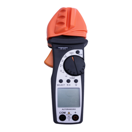
TM-1016 4. OPERATING INSTRUCTIONS 4.1. INSTRUMENT DESCRIPTION 4.1.1. Commands description LEGEND: 1.Inductive clamp Jaw 2.Safety guard 3.Data hold 4. Jaw Trigger 5. Rotary Range Selector 6. SELECT Button 7. Backlight display button 8. Range hold button HT4018 9. LCD 10. COM Jack 11.+Jack... -
Page 8: Use Of Rubber Test Leads Holster
TM-1016 4.1.3. Use of rubber test leads holster One of the accessories is a rubber holster that, inserted on the clamp, can hold one of the two test leads, like showed in Fig. 3 Fig. 3: Use of rubber test lead holster This rubber holster has a very practical use. -
Page 9: Description Of Rotary Switch Function
TM-1016 4.3. DESCRIPTION OF ROTARY SWITCH FUNCTION 4.3.1. AC/ DC Voltage measurement WARNING WARNING Maximum input for AC/DC Voltage measurements is 600V. Do not attempt to take any voltage measurement that exceeds the limits. Exceeding the limits could cause electrical shock and damage the clamp meter. -
Page 10: Ac/Dc Ua Current Measurement
TM-1016 4.3.2. AC/DC uA current measurement Fig. 5: Use of clamp for AC/DC uA current measures 1. Select the “ ” position of selector functions the uA AC or uA DC. 2. Insert the test leads into the jack, the red lead into ”+” jack, and the black lead into the COM jack. -
Page 11: Resistance Measurement
TM-1016 Fig. 6: Use of clamp during AC current measurement 1. Select “ ” position. 2. Open the clamp and put the tested conductor in the center of the clamp jaw (see paragraph 4.1.2), refer to Fig. 6. 3. The current measured will be displayed with automatic detection of the appropriate range. -
Page 12: Continuity Test
TM-1016 Ω/ Ω 1. Select the function “ ” or the function “ ”. 2. Insert the test leads into the jacks. The red lead into ”+” jack, and black lead into COM jack, as shown in Fig. 7. 3. Connect the test leads to the circuit, the voltage measured will be displayed with automatic detection of the appropriate range. -
Page 13: Capacitance Measurement
TM-1016 4.3.6. Capacitance measurement WARNING WARNING Before measuring the capacitor, please be sure to remove power from the circuit being tested and discharge all the capacitors. Before discharge of voltage from the capacitor,please note the safe discharge is to use a 100K Ω... -
Page 14: Temperature Measurement
TM-1016 4.3.7. Temperature measurement Fig. 10: use of clamp for temperature measure 1. Select “TEMP” range. 2. Insert the test leads into the jacks, the red test lead play into ”+” jack, and the black test lead plug into COM jack, as shown in Fig.10. -
Page 15: Fuse Replacement
TM-1016 5.3. FUSE REPLACEMENT WARNING WARNING The fuse is an integral part of the overvotage protection. When fuse replacement is necessary, See specifications for the correct type, size and capacity. Using any other type of fuse will void the overvoltage protection ration rating of the unit. - Page 16 TM-1016 DCV (Auto/Manual) Range Resolution Accuracy Input Impedance Overload Protection 11MΩ ± (0.8%+2) DC/AC 10mV 660V rms 10MΩ 400V 100mV ± (1.0%+2) 600V ACV (Auto/Manual) Range Resolution Accuracy 50Hz~500 Hz Input Impedance Overload Protection 11MΩ ± (1.0%+3) DC/AC 10mV 660V rms...
-
Page 17: Safety
TM-1016 6.1.1. Safety Comply with: EN 61010-1(2001) and EN 61010-2-032(2002) Insulation: Class 2, double reinforced insulation Pollution: Level 2 For inside use, max height: 2000m Over voltage: CAT III 600V (between ground and input terminal) 6.1.2. General data Mechanical characteristics...
Need help?
Do you have a question about the TM-1016 and is the answer not in the manual?
Questions and answers