Table of Contents
Advertisement
Advertisement
Table of Contents

Subscribe to Our Youtube Channel
Related Manuals for Tenmars TM-195


Summary of Contents for Tenmars TM-195
- Page 1 RF three-Axle Field Strength Meter TM-195 User’s Manual...
- Page 2 HB2TM1950000...
-
Page 4: Table Of Contents
Table of Contents 1 Introduction ................1 2 Simple a method of operation ..........1 3 Fundamentals ................1 3.1 Electric field strength (E): ........... 2 3.2 Magnetic field strength (H): ..........2 3.3 Power density (S): .............. 3 3.4 The characteristic of electromagnetic fields: ..... 3 4 Application ................. - Page 5 9.1 POWER button ............... 20 9.2 Data hold button: .............. 20 9.3 Units button: ..............21 9.4 MAX / AVG Record: ............22 9.5 Manual data memory storing .......... 22 9.6 Backlight Display and Reading in The Dark....23 9.7 XYZ/CALL: ...............
- Page 6 12 Short-term measurements ........... 34 13 Long-term exposure measurements ........36 14 SAFETY INFORMATION ............36 15 SAFETY INFORMATION ............38 16 Battery replacement .............. 40 17 Safety Precaution ..............40 18 End of life ................41...
-
Page 7: Introduction
Introduction This meter is designed for measuring and monitoring Radio– Frequency electromagnetic field strength. The meter is calibrated precisely over the frequency range of 50Mz~3.5 GHZ. Simple a method of operation Press button to power on. To change measuring unit (mV/m), push “... -
Page 8: Electric Field Strength (E)
This meter is used to indicate electromagnetic pollution generated artificially. Wherever there is a voltage or a current, electric (E) and magnetic (H) fields arise. All types of radio broadcasting and TV transmitters produce electromagnetic fields, and they also arise in industry, business and the home, where they affect us even if our sense organs perceive nothing. -
Page 9: Power Density (S)
expressed in units of amperes per meter (A/m). In far field situations, one can calculate the magnetic field for the electric field value. This meter can display the calculated magnetic field strength. 3.3 Power density (S): Power per unit area normal to the direction of propagation, usually expressed in units of watts per square meter (W/m ) or, for convenience, units such as mill watts per square centimeter... - Page 10 λ (wavelength) = C (speed of light) / f (frequency) If the distance to the field source is less than three wavelengths, then we are usually in the near field. If the distance is more than three wavelengths, the far-field conditions usually hold. In near field conditions, the magnetic field value cannot be calculated from the electric field value.
-
Page 11: Application
Application Quite often routine, maintenance and service work has to be done in areas where active electromagnetic fields are present, e.g. in broadcasting stations, etc. Additionally, other employees may be exposed to electromagnetic radiation. In such cases, it is essential that personnel be not exposed to dangerous levels of electromagnetic radiation, such as: High frequency(RF)electromagnetic wave field strength ... - Page 12 Wireless LAN (Wi-Fi) detection, installation. Spy camera, wireless bug finder. Cellular /Cordless phone radiation safety level. Microwave oven leakage detection. Personal living environment EMF safety. EN-6...
-
Page 13: Features
Features The meter is a broadband device for monitoring high- frequency radiation in the range from 50MHz to 3.5GHz The non-directional electric field antenna and high sensitivity also allow measurements of electric field strength in TEM cells and absorber rooms. The unit of measurement and the measurement types have ... - Page 14 a person exposed to the field. This power level must be kept as low as possible at high frequencies. The meter can be set to display the instantaneous value, the maximum value measured or the average value. Instantaneous and maximum value measurements are useful for orientation, e.g.
-
Page 15: Identifying Parts
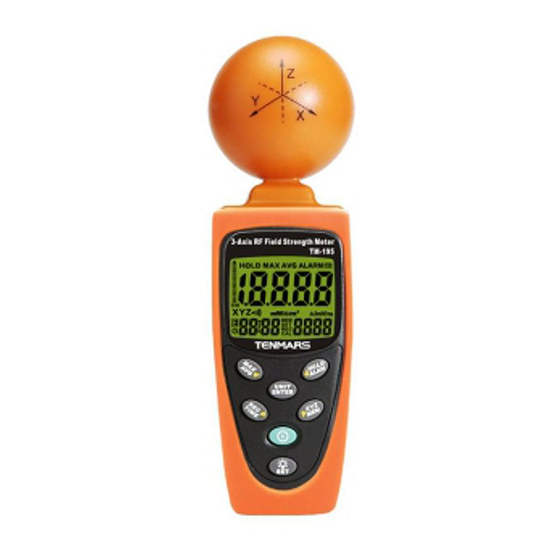
Identifying Parts EN-9... - Page 16 RF three-Axle Sensor. Liquid-crystal LCD MAX / AVG Button. Record / Time Button. Power Button. UNIT / ENTER switch Button. Hold / Up Button. EN-10...
-
Page 17: Lcd Description
Backlight/Down Button. XYZ / MEM button. Tripod mounting screw. Battery cover. LCD description EN-11... -
Page 18: Specifications
1. Primary Display 13. E symbol 2. Hold symbol 14. Auto power off symbol 3. Analogue bar graph 15. Time unit (month:day) 4. MAX symbol (hour: minute) (second) 5. AVG symbol 16. MEM reading symbol 6. Low battery symbol 17. SET symbol 7. - Page 19 Measurement method: Digital, triaxial measurement. Directional characteristic: Isotropic, triaxial. Measurement range selection: one continuous range. Display resolution:0. 1mV/m, 0.1µA/m, 0.001µW/m2, 0.001µW/cm2 Setting time: typically 1.5s (0 to 90% measurement value.) Sample rate: 1.5 times per second. ...
- Page 20 Operating temperature range: 0°C to + 50°C Operating humidity range: 25% to 75 % RH Storage temperatures range: -10°C to +60°C Storage humidity range: 0% to 80% RH Dimensions: 60(L)*60(W)*195(H) mm. Weight (including battery): Approx.200g. ...
-
Page 21: Electrical Specifications
8.2 Electrical specifications Unless otherwise stated, the following specifications hold under the following conditions: The meter is located in the far field of a source; the sensor head is pointed towards the source. Ambient temperature: +23 °C ±3°C. Relative air humidity ... - Page 22 0.01V/m~ 20.0 V/m. 0.1mA/m ~ 532.6mA/m, 0.01W/m ~106.94mW/m Dynamic range: Typically 75dB. Absolute error at 1V/m and 2.45GHz: ± 1.0 dB. Frequency response: Sensor taking into account the typical CAL factor: ± 2.4dB (50 MHz to 1.9 ...
- Page 23 mW/cm (11 V/m) per axis. Overload limit: (0 to50°C): ± 0.2dB. EN-17...
-
Page 24: Units Of Measurement
8.3 Units of measurement The meter measures the electrical component of the field; the default units are those of electrical field strength (mV/m or V/m). The meter converts the measurement values to the other units of measurement, i.e. the corresponding magnetic field strength units (µA/m or mA/m) and power density units (µW/m , mW/m or µW/cm... - Page 25 Instantaneous: The display shows the last value measured value measured by the sensor, no symbol is displayed. Maximum instantaneous (MAX):The digital display shows the highest instantaneous value measured, the “MAX “symbol is displayed. Average (AVG): The digital display shows the average value measured, the “AVG”...
-
Page 26: Measurement Procedures And Preparation
Measurement Procedures and Preparation Battery loading: Remove the battery cover on the back and put a 9V battery inside. Battery replacement: When the symbol of “ ” appears on the LCD display, the battery should be replaced with a new one. The battery symbol will be displayed on the LCD, this is battery low indicator. -
Page 27: Units Button
9.3 Units button: Change units with the “UNITS” key as follows. Electric field strength (V/m) Computed magnetic field strength (mA/m). Computed power density (mW/m Computed power density (μW/cm Press “ ” button and push “ ”button to change the unit. Possible units: mV/m, V/m, µA/m , mA/m, µW/m , mW/m µW/cm EN-21... -
Page 28: Max / Avg Record
9.4 MAX / AVG Record: Press “ ” key to switch to the next display. The display switches from MAX to AVG to MAX/AVG and back to MAX. for 3 seconds Press and hold “ ”key to disable this function. The maximum storage is up to 99 minutes and 99 seconds After this period of time, updating will be completed automatically and then the LCD displays... -
Page 29: Backlight Display And Reading In The Dark
9.6 Backlight Display and Reading in The Dark. Press “ key backlight light ” on. Again Press button to power off Backlight light turns off automatically after 30 seconds. 9.7 XYZ/CALL: Press this key to change sensor axis selector :”All axis” → “X axis “→... -
Page 30: Viewing Data Records
to turn off the function is on. Press hold alarm function. When the Alarm is ON, the display shows 9.9 Viewing Data Records Press hold “ ”button and press“ ”button to view the saved data records Use “ ” or “ ”... -
Page 31: Clock Lcd Display
9.10 Clock LCD Display Press hold button for more than seconds to select the display method of the Year, Month, Date, hour and Second. This meter’s clock uses 24 hour time setting. “2010/01/07 00: 02” “:00”. Default time mode setting is EN-25... - Page 32 EN-26...
-
Page 33: Setup Mode
10 Setup Mode Press hold “ ” button and “ ” button to enter the setup mode. Press “ ” button to change the setup function. (Setup function see Note1) Push “ ” button to save setup data Note1: you can set up 6 different functions in setup mode Clock Setup setup 1 : Setting the alarm limit value (ALARM) setup 2 : Clear data logger memory... -
Page 34: Setting The Alarm Limit Value (Alarm)-2
This meter clock is 24 hour time setting. Use “ ” or “ ” to select the digit you want to adjust Use “ ” or “ ” button to change digit(Hour→day→Month→year→Minute). Press “ ” button to save the setting. Date/Time default format:2009/12/21 12:12. - Page 35 alarm limit value can be edited in the displayed V/m unit. The ALARM setting range is from 0.001 to 999.9V/m. ALARM default is set at 999.9V/m. Alarm limit function is only used for total three axial value comparator. Press and hold on “ ”button and press “...
-
Page 36: Del Data Logger Memorysetup-3
10.3 DEL data logger memorysetup-3 Press and hold on “ ”button and press “ ” button to Setup Mode Press button three times to clear data logger memory for last record setting mode (3.SET). ’ Press” key in the display ‘’ ’... -
Page 37: Auto Power Off Time Function Setup-5
Press“ ” “and “ “ ” to select the desired setting value X1 X10 X100 Press “ ” key to store the new setting value and exit. 10.5 Auto Power Off Time function setup-5 If you want to disable auto power off, please hold “ ”... -
Page 38: Setting The Calibration Factor (Cal)-6
10.6 Setting the calibration factor (CAL)-6 please hold “ ” button and press “ ” button to Setup Mode press “ ” button six times to turn on the meter to enter the calibration factor, The CAL setting range is from 0.10 to 9.99. Press “... - Page 39 The field strength value measured internally is multiplied by the value of CAL that has been entered and the resulting value is displayed. The CAL setting range is from 0.10 to 9.99. The CAL factor is often used as a means of entering the sensitivity of the field sensor in terms of its frequency response in order to improve measurement accuracy.
-
Page 40: Making Measurements
11 Making measurements Important: The following effect will be noted with all field strength meters: If the sensor is moved quickly, excessive field strength values could be displayed. This effect is caused by electrostatic charges. Recommendation: Hold the meter steady during the measurement. 12 Short-term measurements Application: Use either the “instantaneous”... - Page 41 Make several measurements at various locations around your work place or the interested areas as described above. This is particularly important is the field conditions are unknown. Pay special attention to measuring the vicinity of possible radiation sources. Apart from active sources, those components connected to a source may also act as radiators.
-
Page 42: Long-Term Exposure Measurements
13 Long-term exposure measurements Location Place the meter between yourself and the suspected source of radiation. Make measurements at those points where parts of your body are nearest to the source of radiation. Note: Use the “Average” or” Max average” modes only when the instantaneous measurement values are fluctuating greatly. - Page 43 Before making a measurement, check if the low battery symbol” ” is shown on the display as soon as the meter is switched on. Change the battery if the symbol is displayed. In the case of prolonged storage, it is preferable to remove the battery from the meter.
-
Page 44: Safety Information
15 SAFETY INFORMATION DANGER EN-38... - Page 45 In some cases, work in the vicinity of powerful radiation sources can be a risk of your life. Be aware that persons with electronic implants (e.g. cardiac pacemakers) are subject to particular dangers in some cases. Observe the local safety regulations of the facility operation.
-
Page 46: Battery Replacement
16 Battery replacement Turn off the instrument. WARNING If the symbol “ ” appears on the LCD, please replace the battery immediately Remove the battery cover Replace the battery. Install the battery cover. 17 Safety Precaution For cleaning the ... -
Page 47: End Of Life
instrument use a soft dry cloth. Never use a wet cloth, solvents or water, etc.. Operation Altitude: Up to 2000M. Operating Environment: Indoors use. This instrument has been designed for being used in an environment of pollution degree 2. 18 End of life Caution: this symbol indicates that equipment and its accessories shall be subject to a... - Page 48 EN-42...
- Page 49 EN-1...
- Page 50 EN-2...
- Page 51 TENMARS ELECTRONICS CO., LTD 6F, 586, RUI GUANG ROAD, NEIHU, TAIPEI 114, TAIWAN. E-mail : service@tenmars.com http : //www.tenmars.com...
Need help?
Do you have a question about the TM-195 and is the answer not in the manual?
Questions and answers