Table of Contents
Advertisement
Quick Links
Advertisement
Table of Contents

Related Manuals for HT HT9020


Summary of Contents for HT HT9020
- Page 1 Copyright HT ITALIA 2016 Release 1.02 - 01/03/2016...
-
Page 3: Table Of Contents
HT9020 Table of contents: 1. PRECAUTIONS AND SAFETY MEASURES ................2 1.1. Preliminary instructions ........................2 1.2. During use ............................3 1.3. After use ............................3 1.4. Definition of measurement (overvoltage) category ................3 ... -
Page 4: Precautions And Safety Measures
HT9020 1. PRECAUTIONS AND SAFETY MEASURES The instrument has been designed in compliance with directive IEC/EN61010-1 relative to electronic measuring instruments. For your safety and in order to avoid damaging the instrument, please carefully follow the procedures described in this manual and read all notes preceded by the symbol paying the utmost attention. -
Page 5: During Use
HT9020 1.2. DURING USE Please carefully read the following recommendations and instructions: CAUTION Failure to comply with the Caution notes and/or Instructions may damage the instrument and/or its components or be a source of danger for the operator. Before activating the switch, remove the conductor from the clamp jaw or disconnect the test leads from the circuit under test. -
Page 6: General Description
HT9020 2. GENERAL DESCRIPTION The HT9020 instrument carries out the following measurements: DC and AC+DC TRMS voltage DC and AC+CD TRMS current Phase sequence and conformity test AC powers and power factor on single-phase and/or balanced three phase systems ... -
Page 7: Preparation For Use
HT9020 3. PREPARATION FOR USE 3.1. INITIAL CHECKS Before shipping, the instrument has been checked from an electric as well as mechanical point of view. All possible precautions have been taken so that the instrument is delivered undamaged. However, we recommend generally checking the instrument in order to detect possible damage suffered during transport. -
Page 8: Operating Instructions
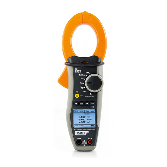
HT9020 4. OPERATING INSTRUCTIONS 4.1. INSTRUMENT DESCRIPTION 4.1.1. Description of the controls CAPTION: 1. Inductive clamp jaw 2. AC voltage indicator LED 3. Jaw trigger 4. Rotary selector switch 5. H/ESC/ 6. F1,F2,F3,F4/OK function keys 7. LCD display 8. Input terminal V... -
Page 9: Hand Protection
HT9020 4.1.3. Hand protection CAPTION: 1. Hand protection 2. Safe area Fig. 3: hand protection Always keep your hands under the hand protection. This protection is always located in a suitable position to guarantee a correct safety distance from possible exposed or live parts (see Fig. -
Page 10: Function Keys Description
HT9020 4.2. FUNCTION KEYS DESCRIPTION 4.2.1. F1, F2, F3, F4/OK keys The F1, F2, F3, F4/OK keys perform different functions according to the measurement set (for detailed information, see the single functions). 4.2.2. H/ESC/ A single press activates the Data HOLD function and the value of the measurement quantity is frozen at display. -
Page 11: Operating Instructions
HT9020 5. OPERATING INSTRUCTIONS 5.1. INSTRUMENT SETTINGS By positioning the selector switch to “Settings”, the screen aside will appear, containing the possible settings of the instrument. L a n g u a g e : Press F1 (Sel) key to see the different selections. Press F2, F3 E n g l i s h (, ) keys to modify the settings of the selected items and F4... -
Page 12: Dc Voltage Measurement
HT9020 5.3. DC VOLTAGE MEASUREMENT CAUTION The maximum DC or AC+DC input voltage is 1000V. When the display shows “> 999.9V”, it means that the maximum value that clamp is capable of measuring has been exceeded. Exceeding these limits could result in electrical shocks to the user and damage to the instrument. - Page 13 HT9020 4. Connect red cable to input lead V and black cable to input lead COM then position the leads at the desired points of the circuit under test (see Fig. 5) 5. The screen shows an example of DC Voltage measurement. Mod 9 .
-
Page 14: Ac/Ac + Dc Voltage Measurement
HT9020 5.4. AC/AC + DC VOLTAGE MEASUREMENT CAUTION The maximum AC/AC+DC input voltage is 1000V. When the display shows “> 999.9V”, it means that the maximum value which clamp is capable of measuring has been exceeded. Exceeding these limits could result in electrical shocks to the user and damage to the instrument. - Page 15 HT9020 4. Connect red cable to input lead V and black cable to input lead COM then position the leads to the desired points of the circuit under test (see Fig. 6) 5. The screen shows an example of AC voltage measurement.
-
Page 16: Voltage Harmonics Measurement
HT9020 5.4.1. Voltage Harmonics measurement 1. Press F2 (Har) key to select the screen of voltage harmonics Har Fnc as shown nearby. Press again F2 (RMS) to go back to 5 0 . 0 H z voltage measurement screen 2 2 0 . 5 2. -
Page 17: Phase Sequence And Phase Conformity
HT9020 5.4.2. Phase Sequence and Phase Conformity CAUTION While measuring, the instrument must be held in the operator’s hand. Phase sequence test Fig. 7: Verification of phase sequence 1. Press F1 (Mod) to open the drop-down menu shown on the screen nearby and select the “Ph Seq”... - Page 18 HT9020 CAUTION If the frequency of the measured voltage is lower than 42.5Hz or higher than 69Hz, the display shows the message “F<42.5 Hz” or “F>69 Hz” and phase detection does not start. 5. When a voltage higher than or equal to 100V is detected, the...
- Page 19 HT9020 9. If the two phases, to which the test lead has been connected, are in the correct sequence, the message “123” is displayed. P h S e q If the phase sequence is incorrect, the message “132” is displayed 1 2 3 10.
- Page 20 HT9020 3. When a voltage higher than or equal to 100V is detected, the instrument emits a sound signal (buzzer) and the message P h S e q “Meas” is displayed. Do not press any key and keep the test...
-
Page 21: Dc Current Measurement
HT9020 5.5. DC CURRENT MEASUREMENT CAUTION The maximum measurable DC current is 1000A. When the display shows “> 999.9A”, it means that the maximum value that the clamp is capable of measuring has been exceeded. Exceeding these limits could result in electrical shocks to the user and damage to the instrument ... - Page 22 HT9020 5. Connect the cable to the middle of the clamp jaws, in order to get accurate measurements (see Fig. 9). Use the marks as a reference (see Fig. 2) 6. The screen shows an example of DC current measurement.
-
Page 23: Ac/Ac + Dc Current Measurement
HT9020 5.6. AC/AC + DC CURRENT MEASUREMENT CAUTION The maximum measurable AC/AC+DC current is 1000A. When the display shows “> 999.9A”, it means that the maximum value that the clamp is capable of measuring has been exceeded. Exceeding these... - Page 24 HT9020 5. Connect the cable to the middle of the clamp jaws, in order to get accurate measurements (see Fig. 10 – left part). Use the marks as a reference (see Fig. 2) 6. The screen shows an example of AC current measurement.
-
Page 25: Current Harmonics Measurement
HT9020 5.6.1. Current Harmonics measurement 1. Press the F2 (Har) key to select the screen of current Har Fnc harmonics as shown nearby. Press again the F2 (RMS) to go 5 0 . 0 H z back to current measurement screen 1 0 0 . -
Page 26: Dynamic Inrush Current Measurement
HT9020 5.6.2. Dynamic Inrush current measurement CAUTION The maximum measurable AC/AC+DC current is 1000A. Do not measure currents exceeding the limits given in this manual. Exceeding these limits could result in electrical shocks to the user and damage to the instrument. - Page 27 HT9020 6. Press F2 (Dsp) to select the available values, as follows: PK Peak value in 1ms Max RMS value in 16.7ms Max RMS value in 20ms 18.2 Max RMS value in 50ms Max RMS value in 100ms ...
-
Page 28: Dc Power And Energy Measurement
HT9020 5.7. DC POWER AND ENERGY MEASUREMENT CAUTION The maximum DC input voltage is 1000V and the maximum measurable DC current is 1000A. Do not measure voltages and currents exceeding the limits given in this manual. Exceeding these limits could result in electrical shocks to the user and damage to the instrument ... - Page 29 HT9020 4. Press F4 (Zro) to perform the zero of value at display Par Fnc 0 . 0 0 5. Connect red cable to input lead V and black cable to input lead COM. Position red lead to “+” and black lead to “-” then connect “+” cable to the clamp jaws, respecting the direction of current indicated by the arrow (see Fig.
- Page 30 HT9020 9. Press F4 (Run) to start the energy measurement. A counter in the bottom of the display is activated 0 . 0 0 0 k W h 0 0 0 0 : 0 0 : 0 0 10. Press F4 (Stp) to stop the energy measurement. The correspondent value is displayed.
- Page 31 HT9020 13. While measuring Voltage and Current, press F3 (Fnc) to open the drop-down menu shown on the screen aside. At each subsequent pressure of F4, the cursor will scroll through the available items, as follows: 8 0 . 0 ...
-
Page 32: Ac/Ac+Dc Power And Energy Measurement
HT9020 5.8. AC/AC+DC POWER AND ENERGY MEASUREMENT CAUTION The maximum AC/AC+DC input voltage is 1000V and the maximum measurable AC/AC+DC current is 1000A. Do not measure voltages and currents exceeding the limits given in this manual. Exceeding these limits could result in electrical shocks to the user and damage to the instrument ... - Page 33 HT9020 4. Press F4 (Zro) to perform the zero of value at display Par Fnc 0 . 0 0 5. Connect red cable to input lead V and black cable to input lead COM then perform the connection as indicated in Fig. 12 depending on the type of system under test. Put the phase cable into the clamp jaws respecting the direction of current indicated by the arrow (see Fig.
- Page 34 HT9020 9. Nearby, an example of measurement of AC voltage and Par Fnc current in a single phase system. 5 0 . 0 H z 2 2 9 . 7 9 9 . 6 10. Press F2 (Par) to open the drop-down menu shown on the screen aside and select the “Harm Voltage”...
- Page 35 HT9020 14. Press F3 (Fnc) to open the drop-down menu shown on the ◄ screen aside. At each subsequent pressure of key F3, the cursor will scroll through the available items, as follows: Max: it constantly displays the maximum RMS value of the selected voltage or current harmonic ...
- Page 36 HT9020 18. Press F4 (Stp) to stop the energy measurement. The Par Fnc corresponding value is displayed. Press F4 (Run) again to 5 0 . 0 H z zero the counter and start a new energy measurement. 2 . 2 4 2 k W h 0 .
- Page 37 HT9020 22. Pressing F4 (OK), the selected item is confirmed. Nearby, an Par Fnc example with active Max function. The display shows the M a x 5 0 . 0 H z active function. 8 0 . 0 2 0 . 0 23.
-
Page 38: Resistance And Continuity Test Measurement
HT9020 5.9. RESISTANCE AND CONTINUITY TEST MEASUREMENT CAUTION Before attempting any resistance measurement, remove power from the circuit under test and discharge all capacitors, if present. Fig. 13: Resistance measurement 1. Positioning the selector switch to “ ”, the screen aside will appear. - Page 39 HT9020 4. Connect red cable to the input lead V and black cable to the input lead COM, then connect the instrument as described in Fig. 13 5. The screen shows an example of Resistance measurement. 20.0 kΩ 6. Press F1 (Mod) to open the drop-down menu shown on the screen aside and select the “Continuity”...
- Page 40 HT9020 11. While measuring Resistance or Continuity, press F2 (Fnc) to open the drop-down menu shown on the screen aside. At each subsequent pressure of F2, the cursor will scroll through the available items, as follows: Max: it constantly displays the maximum resistance value 50.0...
-
Page 41: Maintenance
HT9020 6. MAINTENANCE 6.1. GENERAL INFORMATION 1. The instrument you purchased is a precision instrument. While using and storing the instrument, carefully observe the recommendations listed in this manual in order to prevent possible damage or danger during use. 2. Do not use the instrument in environments with high humidity levels or high temperatures. -
Page 42: Technical Specifications
HT9020 7. TECHNICAL SPECIFICATIONS 7.1. TECHNICAL CHARACTERISTICS Accuracy indicated as ±[%rdg + (num digit * resolution)] referred to 23°C ± 5°C, < 80%HR. DC Voltage Protection against Range Resolution Accuracy overcload 0.1 999.9V (1.0%rdg+3dgt) 1000VDC/ACrms 0.1V Input impedance: 1MΩ... - Page 43 HT9020 Phase sequence and phase coincidence Protection against Range Frequency overload 100 1000V 42.5 69Hz 1000VDC/ACrms Input impedance: 1MΩ DC Power Range [kW] Resolution [kW] Accuracy 0.00 99.99 0.01 (3.0rdg+3dgt) 100.0 999.9 Input impedance: 1MΩ, Accuracy referred for Voltage > 10V, Current ≥ 2A...
-
Page 44: Reference Guidelines
HT9020 7.1.1. Reference guidelines Safety: IEC/EN61010-1, IEC/EN61010-2-032 EMC : IEC/EN61326-1 Technical documentation: IEC/EN61187 Safety of measuring accessories: IEC/EN61010-31 Insulation: double insulation Pollution level: Max height of use: 2000m Measurement category: CAT IV 600V / CAT III 1000V to gnd, max 1000V between inputs 7.1.2. -
Page 45: Service
HT9020 8. SERVICE 8.1. WARRANTY CONDITIONS This instrument is warranted against any material or manufacturing defect, in compliance with the general sales conditions. During the warranty period, defective parts may be replaced. However, the manufacturer reserves the right to repair or replace the product. -
Page 46: Appendix - Theoretical Outline
HT9020 9. APPENDIX – THEORETICAL OUTLINE 9.1. CALCULATION OF POWERS IN “AC 1P” MODE The instrument measures the values of Rms Voltage and Rms Current and calculates the average Power values for each period. The formulas for power calculation are: ... -
Page 47: Voltage And Current Harmonics
HT9020 9.4. VOLTAGE AND CURRENT HARMONICS Any periodic non-sinusoidal wave may be represented by a sum of sinusoidal waves, each with a frequency which is a whole multiple of the fundamental, according to the relationship: ... -
Page 48: Limit Values For Harmonics
HT9020 9.5. LIMIT VALUES FOR HARMONICS Standard EN50160 prescribes the limits for the Voltage Harmonics that Energy Provider may introduce into the network. Under normal operating conditions, at any time in a week, 95% of the efficient values of... - Page 49 HT9020 Consequence resulting from presence of harmonics Generally, harmonics of even, 2 etc. order do not create problems. Designers must consider the following points when designing a power distribution system containing harmonic currents: Installation parts Effects traceable to Harmonics Non-uniform heating of internal fuse element and consequent overheating which can also lead to Fuses an explosion of the fuse casing.
- Page 52 Fax: +55 19 9979.11325 eMail: info@htinstruments.es eMail: ht@htitalia.it eMail: vendas@ht-instruments.com.br Web: www.htinstruments.es Web: www.ht-instruments.com Web: www.ht-instruments.com.br HT INSTRUMENTS USA LLC HT INSTRUMENTS GMBH HT ITALIA CHINA OFFICE 3145 Bordentown Avenue W3 Am Waldfriedhof 1b 意大利HT中国办事处 08859 Parlin - NJ - USA...
Need help?
Do you have a question about the HT9020 and is the answer not in the manual?
Questions and answers