
Related Manuals for Oldham MX43


Summary of Contents for Oldham MX43
- Page 1 MX43 Central Digital and Analog Measurement Unit User Manual P/N : NPM43GB Revision : A...
- Page 2 Edition: July 2010 revision 0. All rights reserved. The reproduction of all or any section of this document in any form whatsoever without the written permission of Industrial Scientific – Oldham S.A.S. is forbidden. The information contained in this manual is accurate to our knowledge.
- Page 3 Introduction to the Application...
- Page 4 Important Information .................. 7 Liability Limits ....................7 Chapter 2 І General Introduction ............. 8 Purpose of the MX43 Central Measurement Unit......8 This central unit is intended for the continuous measurement and control of the gases present in the atmosphere......8 The COM43 Application................
- Page 5 І Principal references ..........54 Chapter 9 І Certificate of Compliance ........56 Chapter 10 І Technical Specifications........... 57 MX43 Central Unit ................57 Relay Module..................... 60 16-Logic Input Module ................61 8-Analog Input Module................61 4-Analog Input Module................61 Chapter 11 І...
-
Page 6: Chapter 1 І General Information
In spite of our efforts to produce an error-free manual, it may nonetheless contain some unintentional technical inaccuracies. In the client’s interest, Industrial Scientific Oldham reserves the right to modify the technical characteristics of its equipment to increase their performance without prior notice. -
Page 7: Safety Instructions
MX43 central unit, injuries, loss of time, financial or material loss, or any direct or indirect consequence of loss occurring in the context of the use or impossibility of use of the product, even in the event that Industrial Scientific Oldham has been informed of such damage. -
Page 8: Chapter 2 І General Introduction
Figure 1: Wall-mounted MX43 and examples of the modules. The system primarily comprises: ■ a wall-mounted MX43 (4 or 8 lines) or rack-mounted MX43 (8 lines); ■ different modules (detector with digital or analog output, logic inputs, analog inputs, relay outputs, and analog outputs). - Page 9 16 logic inputs Analog Module detectors 4 * 4-20 mA outputs 8 analog inputs Analog recorders Figure 2: Example of an MX43 configuration using different analog and digital detectors as well as digital modules. 2 – General Introduction...
-
Page 10: The Com43 Application
Table 1: Summary of the maximum configurations as per the central unit. The COM43 Application This is intended for setting the MX43 parameters from a PC in the Windows® environment. The operation and use of this application is the subject of a specific training course. -
Page 11: Chapter 3 І Mechanical Installation
MX 43 Central Measurement Unit Location The MX43 shall be installed in premises without explosive atmospheres, away from direct sunlight exposure, and protected from humidity, dust, and temperature variations. It shall preferably be located in a place under supervision (guardhouse, control room, or instrument room, for example). - Page 12 Use 2 fixing screws 4x25 mm for fixing the support of the case. Figure 5: Fixing of the wall mounted version MX43 with a support plate. Setting-up of a 19” Rack – 4 U Access to the unit must be ensured in order to facilitate adjustments and monitoring, and likewise in the back in order to allow easy access to the different connectors at the rear.
-
Page 13: Digital Modules
Heavy gases are detected close to the ground, while lighter gases are present along the ceiling. If necessary, contact Industrial Scientific Oldham for any questions regarding proper detector positioning. Fixing... - Page 14 MX43 User manual...
-
Page 15: Chapter 4 І The Mx43 Central Unit
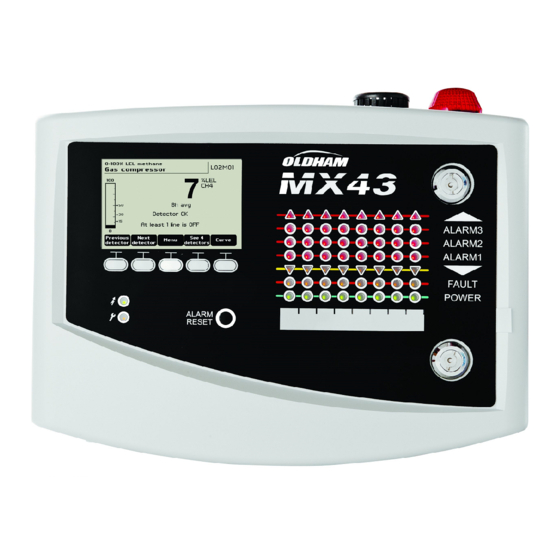
Zone 2 status indicator Alarm release key Integrated siren (option) Free identification of zones Integrated flash (optional) Strip for locating zones Lock Handle Start/Stop indicator Figure 8: External view of the wall-mounted and rack-mounted versions. 4 – The MX43 Central Unit... - Page 16 Communication failure. Absence or failure of line modules. A communication failure is signaled by the activation of the internal buzzer, the presence of the orange failure indicator and via the default relay. No digital module active on the line. MX43 User manual...
- Page 17 Connector for the connection of a remote release (dry contact NO.) Power supply sector input. Protective secondary ground connection. USB connector for connection with the PC supporting COM43 application. Programming switch. CR2032 lithium battery. 4 – The MX43 Central Unit...
- Page 18 Connector for USB key (future function). Allows the loading of data from the MX43 to the PC (values measured, history, etc.) or from the PC to the MX43 (transfer of settings, updating of software loaded in MX43, storage of measurements).
-
Page 19: Front Face
Zone Status Indicators (C) Eight bars of 7 indicators each are displayed on the central unit. The 4 bars to the right are not operative on a 4-line MX43. Each bar represents a geographic area of the complete installation and not the 4 or 8 lines of the MX43. - Page 20 Flash and siren (D and E) Siren (Figure 11, D) Located in the upper portion of the box, the siren is optionally available solely in the wall-mounted version. It is always discontinuous and is configured via the COM43 application. MX43 User manual...
- Page 21 Located in the upper portion of the box, the Flash is optionally available solely in the wall-mounted version. It is configured via the COM43 application. The technical indicators (F and G) These two indicators reflect the status of the MX43. Icon Function Green general start/stop indicator denoting the power supply status - Fixed: Correct power supply.
-
Page 22: Alarm And Relay Thresholds
Alarm thresholds, relay programming, the management of time delays, and methods of release are controlled over the COM43 application. Note: It is possible to modify an alarm limit via the Programming menu of MX43. Parameters of Detector alarms It is possible to program the following for each detector: ■... -
Page 23: Name Plate
Note: The failure relay cannot be programmed via the COM43 application, but is activated on the occurence of a failure. Name Plate The name plate is attached on the right side of the MX43. It contains the following information: ■ Function and type of equipment. - Page 24 MX43 User manual...
-
Page 25: Chapter 5 І Digital Modules
Digital modules are configured via the COM43 application. Addressable Digital Modules These modules are connected on each of the available 4 or 8 lines of the MX43, up to a limit of 32 modules on a version of 8-lines or 16 modules on a 4-line version. -
Page 26: Rs485 Transmission
MX43 Terminal (detector, module) Figure 14: Principle of connecting modules to a MX43 line. An incorrect installation of the cables or cable glands can cause measurement errors or a malfunctioning of the system. Do not lay the cables close to equipment such as engines, transformers, or lines generating important magnetic fields. - Page 27 Swiches Switches (ON = 1; OFF = 0) (On: 1; OFF: 0) Table 5: Addressing table (address depends on switch positions). Remarks: ■ The physical address of a module (1 to 32) must be identical to the address stated on the configuration program COM43 in the central unit. ■...
-
Page 28: Relay Modules
Positive/negative safety set by this switch block (Figure 18, C). Set the switch to ON (positive safety) or OFF (negative safety) according to the safety type desired; each switch acts on the relay having the same number (switch 1 acts on relay 1). MX43 User manual... - Page 29 For the 4-relay module, only switches 1 to 4 are active. E – Programmable relays In its maximum configuration, the MX43 can manage 24 external relays (or 24 modules with 1 stated relay or 3 modules of 8, all stated relays). The relays are programmable indivisually.
-
Page 30: Logic Input Module
C –Logic input connectors Each of these 16 inputs can be connected to a voltage-free contact as per Figure 35. Input status is transmitted by the digital line to the MX43. There is no alarm when the contact is closed. -
Page 31: Analog Input Module
Configuration Configured via the COM 43 application. 8-Analog Input Module Function This digital module enables the monitoring of 8 analog (4-20 mA or Wheatstone bridge) inputs. Digital line 8 analog inputs 4 wires Figure 21: 8-analog inputs. Introduction Ref.. Description Jumper of configuration 4-20mA or a Wheatstone bridge. -
Page 32: Analog Output Module
This digital module delivers 1 to 4 independent analog values (4-20 mA 2 logic inputs outputs) opto-isolated from the values given by the MX43, capable of being independently activated or deactivated: ■ Activated: The 4-20mA signal varies depending on the input. - Page 33 Each of these two terminal jacks (Figure 24, A) may be connected to a voltage- free contact in accordance with Figure 38. Input status is transmitted by the digital line to the MX43. C – Module configuration switches These switches are set according to the following table:...
-
Page 34: Chapter 6 І Electrical Connections
The electrical connections must be carried out by qualified personnel in compliance with the different directives in force in the country of installation. The MX43 does not have a start/stop switch. Certain voltage levels are capable of causing serious injuries or even death. - Page 35 Figure 26: Connection of sector power in wall mounted and rack versions. External 24V DC Power Supply The MX43 can be powered from a 22 to 28 V AC source at 50/3.2 A, 1.5 A max. In this case, connect the 24VDC source to the corresponding terminal jack (Figure 26, A) respecting polarities.
- Page 36 Figure 28: Positioning the battery pack. Earthing The MX43 is intended to be used in the parts of installations corresponding to the category of overvoltage II and pollution degree 2 as per EN/IEC 60947-1. In order to comply with this category of protection, it is absolutely necessary to connect the ground terminal.
- Page 37 (Default) transition to power supply from the backup battery pack, system anomaly, etc). The deletion of this relay is automatic. Table 10: Internal alarm relays. 6 – Electrical Connections...
- Page 38 The RCT dry contacts (nominal resistive load of 2 A at 250 VAC, and 2 A 30 V DC) of the 6 internal relays R1, R2, R3, R4, R5 and Default are deployed on the backplane board of MX43 on the R1, R2, R3, R4, R5 and Default connectors (Figure 30: Internal alarm relay connectors (A).
-
Page 39: Or 8-Relay Modules
Supervised contact Supervised contact 4- or 8-output contacts RTC (250VAC or 30 V To MX43 To next module DC – 2A) or previous module Figure 34: 4- or 8-relay module connections If this module is the last on the line, do not forget to set the switch marked EOL resistor/resistance FDL to ON. -
Page 40: Analog Input Module
8-Analog Input Module To MX43 To next module or previous module Figure 36: Connections of 8-analog input modules for 1 4-20mA detector with 3 wires (explosive gas, toxicity detection). 130x To MX43 To next module Wheatstone bridge type or previous module... - Page 41 Output Output 4-20 mA no. 2 4-20 mA no. 4 To MX43 To the next module or the previous module Figure 38: 4 Analog output module connections. If this module is the last of the line, do not forget to set the jumper switch marked EOL Resistor/FDL resistance to the ON position.
- Page 42 MX43 User manual...
-
Page 43: Chapter 7 І Menus
See page 46 See page 47 See page 48 See page 50 See page 50 ECR_90_91_92_93_94 Figure 38: General menu tree of the MX43. Navigation Key Functions Function Vertical displacement in the selected menu block. Horizontal displacement between two menu blocks. -
Page 44: Display In Normal Mode
■ Curve: Display of the measurement curves of the last 4 hours (Figure 41). The keys allow cursor displacement through the time scale. The vertical dotted line displays the concentration and time stamp of the point being considered. Escape: return to display of values. MX43 User manual... -
Page 45: Main Menu
Zone of indication of activated alarms with blinking threshold display. The screen changes to inverse video (Figure 40, screen on the right). ECR_10 Figure 40: Example of a curve display screen. Main Menu This displays all the management menus of MX43. ECR_12 Figure 41: Main menu. System ■... -
Page 46: Calibration
↑↓ keys. Validate by pressing Enter. Note: Only analog detectors that are not equipped with a local display can be calibrated from the MX43 central unit. For the other detectors, the menu “Sel. Detector” only makes it possible to put them in calibration mode so that they do not activate alarms during their manual calibration. -
Page 47: Stop Recording
paragraph “2 Recording”. Display the calibration gas. ECR_14 Figure 42: Example of the “Select detectors” screen. 2 Start Recording ■ Yes: Launches the recording of calibration measurements for the selected detectors. From this moment onwards, all the calibration measurements are recorded for these detectors. - Page 48 1. Press Escape to launch the reboot of the selected cells. 2. Proceed next to the changing of the cell and then to a calibration of the corresponding detectors via the menus “1 Sel detectors”, “2 recording”, "End recording” and “4 validation”. MX43 User manual...
-
Page 49: Maintenance
Al3, Al1mean, Al2mean, Al3mean, OVS), status (activated = ON or deactivated = OFF) as well as the date and time of occurrence or of the release. The letter “S” appears on the line if the events were obtained when the MX43 was in 7 – Menus... - Page 50 Beyond that, the most recent event deletes the oldest. Previous page, Next page, and Last page access the corresponding pages of the file. Message Significance RELAY Status change of the designated relay. INPUT Status change of the designated input. MX43 User manual...
-
Page 51: Programming
Table 14: Relay and logic input file messages. 4. Working conditions records This displays the actions carried out on the MX43 (simulation mode, calibration mode, programming mode, release request, operation on internal battery), as well as the date and time of beginning and end of the event. - Page 52 LINE 8 Incident on line 8 (short-circuit). CAL O Calibration defect (zero shifted). CAL S Calibration defect (used cell). CAL F Calibration defect (cell oversensitive). CAL D Calibration defect (measurement unstable). Table 16: Material incidents file messages. MX43 User manual...
- Page 53 3. Slave info These data enable maintenance technicians to visualize the communication framework between MX43 and the digital modules. 4. Controller info These data allow technicians to visualize MX43 counters set to zero since the last zero setting. 7 – Menus...
- Page 54 Chapter 8 І Main Part number Description Reference Image MX43 4-line central unit, wall-mounted version 6 514 886 MX43 8-line central unit, wall-mounted version 6 514 884 MX43 8-line central unit, rack version 6 514 885 Module with 8 analog inputs...
- Page 55 Description Reference Image 4-relay module 6 313 962 8-relay module 6 313 963 Flash and buzzer kit 6 314 066 10 – Principales références...
-
Page 56: Chapter 9 І Certificate Of Compliance
Chapter 9 І Certificate of Compliance 9 – Certificate of Compliance... -
Page 57: Chapter 10 І Technical Specifications
Chapter 10 І Technical Specifications MX43 Central Unit Function Function: Central measurement unit with multiple-channel alarm. Number of lines: 4 or 8 as per model. Display and indicators Display: Back-lit graphic LCD Status indicators: - 7 LEDs for each of the 8 lines, or 56 LEDs. - Page 58 ■ Rack version: 482.8 x 177 x 192.5 mm (19’’, 4 U). See Figure 4 and Figure 6. Weight: ■ Wall-mounted version: 4.0 kg. ■ Rack version: 2.0 kg. Protection level: ■ Wall-mounted version: IP55. ■ Rack version: IP 31. MX43 User manual...
- Page 59 Locking: ■ Wall-mounted version: by 2 locks with a key. ■ Rack version: none.
-
Page 60: Relay Module
CSA: as per C22.2 no.152 (current). Relay Module Function Function Management of 4 or 8 relays from the digital signals issued by the MX43. Number of relays: ■ 4 or 8 relays. ■ CRT outputs Relay type: ■ Bistable. ■ Configuration in positive or negative safety by mini-switches. -
Page 61: Logic Input Module
4 bridges - 45°C (4 bridges up to 1 km). - 50°C (4 bridges up to 500 m). Assembly: Snap-on on DIN rail or mounted on the inside of MX43. Dimensions: 125 x 165 x 60 mm. 4-Analog Output Module Function Function: Generation of 1 to 4 analog values. - Page 62 ■ < 5 mA with the 4 lines at stop. ■ < 36 mA for an activated line. ■ < 130 mA for the 4 activated lines. Assembly: Snap-on on DIN rail. Dimensions: 125 x 165 x 60 mm. MX43 User manual...
-
Page 64: Chapter 11 І Index
Mechanical Installation, 7 Digital address module, 22 Menu General tree, 39 Calibration, 42 Information, 45 Flash, 17 Maintenance, 44 Front face MX43, 15 Main Menu, 41 Programming, 42 System, 41 Menus Navigation keys, 39 Module with 16 analog inputs General Introduction, 3... - Page 65 Module with 8 analog outputs Detector module Caracteristics, 55 Fixation, 9 Localization, 9 Siren, 16 Navigation Key Functions, 44 Technical specifications, 51 Programming switch, 14 The MX43 Central unit General information, 5 Remote Release, 39 References, 49 10 - Index...
- Page 66 MX43 User manual...
Need help?
Do you have a question about the MX43 and is the answer not in the manual?
Questions and answers