
Related Manuals for Oldham OLCT 60


Summary of Contents for Oldham OLCT 60
- Page 1 OLCT 60 User manual Fixed Point Gas Monitor Part Number: NPO60GB Revision: D.2 The Fixed Gas Detection Experts...
- Page 2 Copyright June 2018 by Oldham S.A.S. All rights reserved. No reproduction of all or part of this document, in any form, is permitted without the written consent of Oldham S.A.S.. All of the information that is provided in this document is accurate to the best of our knowledge.
-
Page 3: Table Of Contents
Contents Chapter 1 | Overview Purpose ......................9 Operating principle ..................10 Composition of the Detector ............... 11 External view ....................12 Internal view ....................14 Labels and pictograms ................14 Visual indication ..................15 Chapter 2 | Installation Regulations and conditions of use ............. 19 Necessary equipment ................ - Page 4 Metrological performance for the detection of flammable gases or oxygen ......................69 Threaded joints................... 70 Functional Safety ..................70 Reliability data .................... 70 Chapter 11 | Fault and error codes Errors (E xx) ....................73 Faults (dEF xx) ................... 73 OLCT 60 User manual...
- Page 5 It is important that you read this entire manual carefully and thoroughly. Limitation of Liability OLDHAM shall not be held responsible for any damage to the equipment or for any physical injury or death resulting in whole or in part from the inappropriate use or installation of the equipment, non-compliance with any and all instructions, warnings, standards and/or regulations in force.
- Page 6 Warnings This is not a contractual document. In the best interest of its customers and with the aim of improving performance, OLDHAM reserves the right to alter the technical features of its equipment without prior notice. READ THESE INSTRUCTIONS CAREFULLY BEFORE THE FIRST USAGE: these instructions should be read by all persons who have or will have responsibility for the use, maintenance, or repair of the instrument.
- Page 7 Disposal of the equipment European Union only. This symbol indicates that, in conformity with DEEE Directive (2002/96/EC) and according to local regulations, this product may not be discarded together with household waste. It must be disposed of in a collection area that is set aside for this purpose, for example at a site that is officially designated for the recycling of electrical and electronic equipment (EEE) or a point of exchange for authorized products in the event of the acquisition of a new product of the same type.
- Page 8 OLCT 60 User manual...
-
Page 9: Chapter 1 | Overview
Table 1: Comparison of OLCT 60 detectors Each version features two options: OLCT 60 version with on-board sensor. The sensor can either be flameproof or intrinsically safe certified depending on the version of the detector. OLCT 60D version with remote sensor. The sensor can either be flameproof or intrinsically safe certified depending on the version of the detector. -
Page 10: Operating Principle
(gas controller or PLC). Sensor type depends on the gas to be detected and the version of OLCT 60 as shown in Table 1: Comparison of OLCT 60 detectors on page 9. -
Page 11: Composition Of The Detector
Display board Terminal board On-board sensor Enclosure M25 cable gland (until August 2014) Remote sensor Cable for remote sensor Adapter On-board OLCT IR infrared sensor Remote OLCT IR infrared transmitter Figure 1: Main components of OLCT 60 detectors 1 - Overview... -
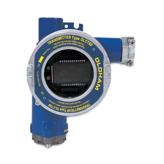
Page 12: External View
On-board OLCT IR infrared sensor head. See 9 for more details. Remote OLCT IR infrared transmitter. See 9 for more details. 012A OLCT 60 OLCT 60D with remote sensor block 012B OLCT 60/OLCT IR on-board OLCT 60/OLCT IR remote Figure 2: OLCT 60 overview OLCT 60 User manual... - Page 13 Difference between FLP and IS sensors Although they have different ATEX marking, intrinsically safe and flameproof sensors are distinguished by the color of the sensor block as following: Flameproof sensor: unpainted stainless steel enclosure equipped with a flame arrestor, Intrinsically safe sensor: blue painted stainless steel enclosure equipped a PTFE membrane.
-
Page 14: Internal View
The detector has two identification labels, as shown below: Certification label Description ATEX marking Type of product Manufacturer's name IECEx marking and ATEX certification temperature range (is not the operating temperature range) Warning Figure 5: Certification label CE and ATEX marking OLCT 60 User manual... -
Page 15: Visual Indication
P/N label This label is located on the side of the enclosure and contains the following information: Description Part Number of the OLCT 60 without sensor Disposal icon Serial Number Figure 6: Side label Visual indication At startup Display shows: Initialization screen. - Page 16 See Fault mode screen L_010A L_010B Figure 8: OLCT 60 in normal operating mode Fault mode screen The display indicates DEF or the fault code (see page 73 for more warning code information). Simultaneously, the FAULT indicator lights on and the icon is displayed.
- Page 17 Gas calibration menu The menu is different depending on whether the OLCT 60 is equipped with an OLCT IR infrared sensor. Normal operating mode (page 31) (page 42) (page 39) L_022_A (page 47) L_022B Figure 11: Gas calibration menu (on the right: OLCT 60 equipped with an OLCT IR infrared sensor) •...
- Page 18 OLCT 60 User manual...
-
Page 19: Chapter 2 | Installation
Chapter 2 | Installation Please read the guidelines on the installation, use and maintenance of detectors for detection of flammable gases and oxygen (standard EN/IEC 60079-29-2) and toxic gases (standard EN 45544-4). Regulations and conditions of use The installation will be done according to current standards for installation in explosive areas especially regulations IEC/EN 60079-14 and IEC/EN 60079-17 (current editions) or according to other national standards. -
Page 20: Detector Positioning
Detector positioning All versions excluding OLCT IR The OLCT 60 will be installed with the sensor pointing downwards. Any tilt of more than 45° from the vertical will lead to an inaccurate measurement. Fixing the enclosure will be performed by using 2 x M6 screws and the appropriate plugs for the supporting material. - Page 21 Fixing the detector will be performed by using 2 x M6 screws and the appropriate plugs for the supporting material. Figure 14: OLCT IR detector MUST be laid horizontally, arrow pointing upwards 30m (100 ft) max. Figure 15: OLCT IR detector must be laid horizontally, arrow pointing upwards 2 - Installation...
-
Page 22: Electrical Specifications
ATEX zone: xx-xx-09/15- EG-SF or EG-FA or EG-PF (U 300 compatible with M87202). The maximum permissible length will depend on the cross-section of the cable conductors (see table) and on the minimum admissible supply voltage at the detector terminals. OLCT 60 User manual... -
Page 23: Cable Connection
Cable connection Turn off the line On the controller: 1. Inhibit any alarms to prevent false alarms during operation. 2. Switch off the power supply to the detector. Opening of the detector Loosen the 4mm hex screw (rep.1) locking the cover before removing the detector cover. - Page 24 Figure 18: armoured cable gland type Cable connection (OLCT 60) Remove power before wiring the OLCT 60 to the controller. The site must be equipotential. Connect the cable to the detector first and then connect the controller. Once the wiring is completed, connect the shield of the cable to the ground terminal of the controller.
- Page 25 Cable connection (OLCT 60/OLCT IR remote) Remove power before wiring the OLCT 60 to the controller. The site must be equipotential. First carry out the connection between the OLCT IR (rep. A) and the detector (rep. B) as shown in Figure 20. The maximum distance is 30 meters (100 feet). The type of cable to use is 01-IQ-09-EG-FA or EG-SF or similar;...
- Page 26 Connect the enclosure ground points to earth according to the regulations with a 4mm² (11 AWG) wire. The OLCT 60 features an internal ground point as well. The internal grounding shall be preferred as the primary equipment ground. Figure 21: OLCT 60 grounding Closing the cover Before connecting the OLCT 60 to the controller, the cover shall be tightly closed.
-
Page 27: Scope Of Use
Similarly, the unit should provide sufficient % of the voltage to compensate for any voltage measuring range Default drop in the cable. Figure 22: OLCT 60 transfer curve 2 - Installation... - Page 28 OLCT 60 User manual...
-
Page 29: Chapter 3 | Commissioning And Operating Modes
Chapter 3 | Commissioning and operating modes The tasks described in this chapter should only be performed by authorized and trained personnel as they are likely to jeopardize the reliability of detection. This chapter describes: how to check the zero how to check the sensitivity the various operating modes Purpose of control... -
Page 30: Commissioning
Integrity of the mechanical mounting (fixings, cable gland, and cover) ensured Powering up detector 1. Inhibit any alarms to avoid false alarms during operation 2. Apply power to the OLCT 60 Stabilization time Before initial calibration allow the detector to stabilize after applying power. Any adjustment before the time indicated will result in an incorrect measurement, which may in turn compromise the safety. -
Page 31: Display Of The Gas Measurement
Display of the gas measurement Normal operating mode Alternately, the display shows the measured concentration and the type of gas. The OK green indicator is lit; the FAULT indicator is off. L_00 Figure 23: Normal operating mode Fault mode In fault condition, the display indicates «dEF» followed by the fault code. -
Page 32: Checking Zero
5. Once the measure is stabilized (approx. 2 minutes), read the value on the display (rep. A). 6. If the expected value does not comply, proceed with the calibration (paragraph Zeroing and sensitivity adjustment, on page 42). 7. Continue with Checking gas sensitivity on the next page. OLCT 60 User manual... -
Page 33: Checking Gas Sensitivity
Checking gas sensitivity For safety reasons, this procedure must be carried out after the control of the zero (page 31). Proceed as follows: Figure 27: Checking gas sensitivity 1. Once the detector is zeroed, connect the calibration cup to the calibration gas cylinder (Pos. - Page 34 OLCT 60 User manual...
-
Page 35: Chapter 4 | Preventive Maintenance
EN/IEC 60079-17 standard in force or with other national standards. Maintenance schedule Gas detectors are safety devices. OLDHAM recommends the regular testing of fixed gas detection installations. This type of test consists of injecting the calibration gas into the detector at a sufficient concentration to activate the pre-set alarms. -
Page 36: Actions
Zero inspection with zero grade air; see page 31. In case of variance, comply with the actions described in this paragraph. Gas sensitivity check; see page 32. In case of variance, comply with the actions described in this paragraph. OLCT 60/ OLCT IR Refer to the specific OLCT IR manual. OLCT 60 User manual... -
Page 37: Maintenance
Chapter 5 | Maintenance Maintenance primarily comprises changing any sensors that no longer meet their initial metrological characteristics. Since they are liable to affect detection reliability, the tasks described in this chapter are reserved for authorized trained personnel only. Inspection and maintenance shall be carried out in accordance with EN/IEC 60079-17 standards in force or with other national standards. -
Page 38: Replacing Sensor Block (Explo, O , Tox, Xpir)
Replace the worn out detector head with an identical new one. Reassemble in reverse order and tighten the locking screw. Power the OLCT 60. Install the OLCT 60 as explained in detail in the Initialization of the sensor block paragraph on page 39. OLCT 60... -
Page 39: Replacing The Olct Ir - Integrated Version
Carry out the connections. Refer to the Connection of the cable (OLCT 60/OLCT IR remote version) paragraph on page 24. Reassemble in reverse. Power the OLCT 60. Install the OLCT 60 as explained in detail in the Initialization of the sensor block paragraph on page 39. 5 - Maintenance... -
Page 40: Initialization Of The Sensor Block
Initialization of the sensor block This procedure resets the electrical parameters of the sensor. Step Action Illustration The Init screen is displayed, place the magnet over L_020B The display indicates «CnF» (Confirmation). L_044 Place the magnet over OLCT 60 User manual... - Page 41 L_06 Countdown starts before return in normal mode. L_059 When the countdown is ended, the display shows the gas measurement. The OLCT 60 is in normal mode. L_020A Subsequently check the gas operation as explained on pages 31 and 32.
-
Page 42: Zeroing And Sensitivity Adjustment (Calibration)
In the event of a voluntary or an automatic abandon of the procedure, the previous values will be maintained. OLCT 60 leaves the maintenance mode and returns to normal operation after 10 minutes of inactivity on the The detector cover shall remain completely closed since the adjustments are carried out through the window. - Page 43 Zeroing Step Action Illustration The calibration menu (CAL) is displayed. L_020C Position the magnet over The display now shows “-0-” indicating the beginning of the zero-setting phase. L_024 Position the magnet over The display indicates the current value. L_026 Place the calibration cup and inject zero grade air at 0.5 to 1 LPM (1 to 2 LPM for OLCT IR versions).
- Page 44 L_034 Adjusting the units The unit digit flashes. Repeat the same procedure as for the hundreds. L_036 Validate the digit of the units by placing the magnet over End of the procedure. OLCT 60 User manual...
- Page 45 Injecting calibration gas Step Action Illustration The display indicates «S» (Sensitivity). L_038 Place the calibration cup on the sensor and inject the span gas at flow rate between 0.5 and 1 LPM (1 to 2 LPM for OLCT IR versions). Position the magnet over The displayed value keeps changing until it stabilizes.
- Page 46 End of the zero-setting and calibration procedure Step Action Illustration The OLCT 60 starts a countdown before returning in normal operation mode. Please note: The countdown time is sensor dependent. L_059 Close the cock of the calibration gas cylinder and remove the calibration cup.
-
Page 47: Adjusting The Optical Zero (Ir-0)
Adjusting the optical zero (Ir-0) (for OLCT IR versions) This menu strictly applies for OLCT IR versions prior to set the zero or the sensitivity or after cleaning optical parts (see page 42). Cleaning the optical parts is described in the manual of the OLCT IR. - Page 48 Place the magnet over to validate the choice. L_046 Please continue as in paragraph Changing over to calibration mode, page 42. Place the magnet over to confirm No and exit the optical zero setting menu. L_048 OLCT 60 User manual...
-
Page 49: Applicable Coefficients For Explosive Gas Calibration
Applicable coefficients for explosive gas calibration Catalytic sensor type VQ1 The applicable coefficients are shown in the following table. Chemical Flash Vapor Coefficient Coefficient Coefficient Coefficient Calibration gas Calibration gas - Calibration gas - Calibration gas Formula point (°C) density CH4 (methane) H2 (Hydrogen) C4H10 (Butane) - Page 50 > 4 3,50 2,80 1,85 1,70 (Mixture) Xylene C8H10 1,00 7,60 4,00 3,20 2,15 1,90 : recommended gas for detector calibration Table 3: Coefficients for the calibration of catalytic detectors equipped with a standard sensor VQ1 OLCT 60 User manual...
- Page 51 4F poison resistant catalytic bead sensor The applicable coefficients are: Chemical LEL % Vapor Formula density Coef Coef Coef Acetone 2,15 13,0 Acetylene Ammoniac 15,0 30,2 Benzene C6H6 2,10 1,05 n-Butane C4H10 Ethane C2H6 15,5 Ethanol C2H6O 19,0 Ethylene C2H4 34,0 n-Hexane C6H14...
-
Page 52: Checking The Line Current
5. The current must be 4 mA (Pos. C) when zero grade air is applied on the sensor and 20 mA when applying span gas of concentration equal to the full scale. 6. Once testing is completed, connect back the signal wire to terminal 1 (Pos. B). OLCT 60 User manual... -
Page 53: Chapter 6 | Accessories
Chapter 6 | Accessories The following accessories do not apply for OLCT 60/OLCT IR. For the latter please revert to the OLCT IR manual. Accessories Utilization Illustration Illustration Tool Kit Opening of the OLCT 60 and 6147870 sensor replacement OLCT Please read OLCT IR manual. - Page 54 Effects on the measurement: none. Effects on response time: may increase by 10% Used for menu selection through Magnet 6155651 the detector glass window. Cable entry M25 / M20 adaptor 6143552 adaptor M25 / ¾ NPT adaptor 6143584 OLCT 60 User manual...
-
Page 55: Chapter 7 | Spare Parts
6 314 203 Sensor block OLCT 60, 0-100% vol. H2 6 314 100 Infrared sensor block 0-5% vol. CO2 for OLCT 60 XP IR 6 314 101 Infrared sensor block 0-10% vol. CO2 for OLCT 60 XP IR 6 314 225... - Page 56 H2-compensated sensor block OLCT 60 CO 0-1000 ppm 6 313 695 Sensor block OLCT 60 H2S 0-30 ppm 6 313 965 Sensor block OLCT 60 H2S 0-30 ppm, no HC-interference 6 313 696 Sensor block OLCT 60 H2S 0-100 ppm 6 313 697...
-
Page 57: Intrinsically Safe Sensors
Sensor block OLCT 60 SI NH3 0-1000 ppm 6 313 895 Sensor block OLCT 60 SI NH3 0-5000 ppm 6 313 694 H2-compensated sensor block OLCT 60 SI CO 0-1000 ppm 6 313 711 Sensor block OLCT 60 SI CO 0-100 ppm 6 313 712... - Page 58 Illustration Description 6 313 737 Sensor block OLCT 60 SI PH3 0-1 ppm 6 313 739 Sensor block OLCT 60 SI HF 0-10 ppm 6 313 738 Sensor block OLCT 60 SI ASH3 0-1 ppm 6 313 747 Sensor block OLCT 60 SI SiH4 0-50 ppm...
-
Page 59: Chapter 8 | Declaration Of Eu Conformity
Chapter 8 | Declaration of EU Conformity The pages (3) below reproduce the EU statements of compliance for the OLCT 60’s series of detectors. 8 – EU conformity... - Page 60 OLCT 60 User manual...
- Page 61 8 – EU conformity...
- Page 62 OLCT 60 User manual...
-
Page 63: Chapter 9 | Technical Specifications
Chapter 9 | Technical Specifications Dimensional characteristics Figure 29: Dimensional characteristics of OLCT 60 detectors with on-board and remote sensor 9 – Technical specifications... - Page 64 Figure 30: Dimensional characteristics of OLCT 60/OLCT IR detectors with on-board or remote sensor OLCT 60 User manual...
-
Page 65: Complete Detector
Non-ambiguity reading: 20 mA (over-range for combustible gas detectors) Maximum resistance per cable Catalytic: 32 loop (1 km and 1.5 mm conductor (with Oldham control Electrochemical: 48 loop (1.5 km and 1.5 mm unit) XP-IR infrared: 48 loop (1.5 km and 1.5 mm... - Page 66 Ex d IIC T4 Gb - Ex tb IIIC T135°C Db : –20 °C à +60°C Note: data above include the cable gland supplied by default along with the OLCT 60 (until August 2014). Starting from August 2014, make sure to use a compatible cable gland compatible and at least flameproof certified (d).
-
Page 67: Measuring Sensors
Measuring sensors Measuring Tempe- % HR Accuracy (ppm) Average Resp. Time Storage time range sensor sensor rature Life T50/T90 (s) (ppm) range (°C) conditions Expectan (months) 9/15 (CH4) +/- 5% (CH4) -25 to +55 0 – 99 Combustible gas Infrared OLCT IR 0-100% LEL >60 +/- 3% (HC) 7/8 (CH4) (f) - Page 68 6 months maximum 6 months maximum 3 months maximum 6 months with weather cover without weather cover (g) -40°C to +85°C. 0 % to 80 % HR 1 bar ± 10 % maximum 6 months OLCT 60 User manual...
-
Page 69: Chapter 10 | Special Instructions For Use In Explosive
General comments The OLCT 60 sensors conform to the requirements of European Directive ATEX 94/9/CE relating to explosive Dust and Gas atmospheres. On account of their metrological performance as tested by the notified body INERIS, the OLCT 60... -
Page 70: Threaded Joints
For this to be so, they must be connected to Oldham controllers type MX 15, MX 32, MX 42A, MX 43, MX 48, MX 52 or MX 62, or otherwise connected to central units with 4-20 mA inputs conforming to section 1.5 of Annex II of ATEX Directive 94/9/CE and compatible with their... - Page 71 OLCT 60 gas detector for the detection of oxygen and combustible gases complies with EN 50104, EN 50057 and EN50271:01. As mentioned in the scope of this last standard, the detector can be used in industrial applications where safety integrity levels 1 or 2 according to IEC 61508 are required.
- Page 72 OLCT 60 User manual...
-
Page 73: Chapter 11 | Fault And Error Codes
Chapter 11 | Fault and error codes E xx Errors ( Errors are exclusively generated when a communication trouble occurs between the sensor and the internal board. Errors are identified in the following format Exx (whereas xx corresponds to the error code). No corrective action is possible for the operator. - Page 76 The Fixed Gas Detection Experts EUROPEAN PLANT AND OFFICES Z.I. Est – rue Orfila CS 20417 – 62027 Arras Cedex FRANCE Tél: +33 (0)3 21 60 80 80 – Fax: +33 (0)3 21 60 80 00 Website: https://gasdetection.3m.com AMERICAS ASIA PACIFIC EUROPE Tel: +1 713-559-9280 Tel: +86-21-3127-6373...
Need help?
Do you have a question about the OLCT 60 and is the answer not in the manual?
Questions and answers