
Related Manuals for Oldham MX48


Summary of Contents for Oldham MX48
- Page 2 GAS AND FLAME DETECTION STACK GAS AND DUST MONITORING We thank you for choosing an OLDHAM SA instrument. We have taken every step to ensure that this equipment continues to give you complete satisfaction. Please read the instruction manual carefully before using the instrument.
- Page 3 OLDHAM SA, even if involved in the sale of the products of OLDHAM SA. * OLDHAM SA shall not be liable for any direct or indirect damage, or any direct or indirect legally awarded damages resulting from the sale and use of any of its products, UNLESS THOSE PRODUCTS WERE SPECIFIED AND CHOSEN BY OLDHAM SA FOR THE USE MADE OF THEM.
-
Page 4: Table Of Contents
1.2. The various printed circuit boards...................9 1.3. INSTALLATION AND CONNECTIONS ..........10 Installation: recommendations..................10 2.1. Electrical connections of the MX48 Unit (Fig. 8)............10 2.2. 2.2.1. Alternative power supply ..................10 2.2.2. DC power supply....................11 Detectors (Figure 12).....................11 2.3. - Page 5 The various menus and their functions ..............30 4.2.2. Block diagram of the scrolling of the various menus..........30 4.2.3. Detailed flow diagrams of each menu..............32 SETTING THE MX48 UNIT INTO SERVICE........45 Programming the unit ....................45 5.1. Programming the measuring channels ................45 5.2.
-
Page 6: Description
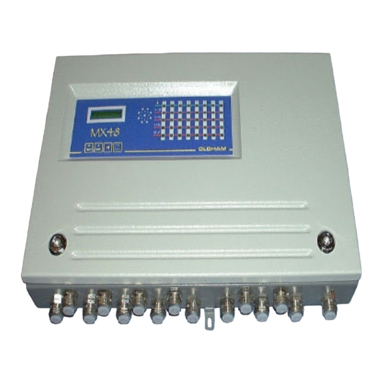
Each channel is connected to one or more detectors installed in the locations to be monitored. The measurement that is output from the detector is displayed on the MX48 unit and compared with alarm thresholds. If thresholds are exceeded, the unit actuates relays which can be used to control external devices. - Page 7 • Wall-mounted box (500 x 340 x 89) • AC or DC power supply • 4 or 8 measuring inputs for detectors • Display of measurement on a plasma display panel (2 lines - 16 characters) • One keypad with four keys on the front panel for the user •...
-
Page 8: The Wall-Mounted Box
1.2. the wall-mounted box The housing of the MX48 is a wall-mounted box consisting of a back casin and a cover which can be pivoted. • Dimensions: Fig. 1 (end of this manual) • Overall view, casing open : Fig. 2 1.3. -
Page 9: Installation And Connections
Electrical connections of the MX48 Unit (Fig. 8) The MX48 unit is equipped with a pulse automatic device which enables to connect 24 V DC voltage in a lack of 220 V AC voltage so we can use no expansive save power supply. -
Page 10: Dc Power Supply
Resistance of detector / unit cable: 16 ohms maximum per wire, i.e. 32 ohms in loop (1 km for cable 3 x 1.5 mm²). Connection on MX48 unit: see Fig. 10 – Example 1 2.3.2. 3-wire detectors 4-20 mA: 3 connecting wires for shielded cable Resistance of detector / unit cable: 16 ohms maximum per wire, i.e. -
Page 11: 2-Wire Detectors 4-20 Ma: 2 Connecting Wires For Shielded Cable
Resistance of detector / unit cable: 32 ohms maximum per wire, i.e. 64 ohms in loop (2 km for cable 2 x 1.5 mm²). Connection on MX48 unit: see Fig. 11. – Example 2 2.3.4. FIRE detectors: 2 connecting wires for shielded cable The current commercial designations are as follows: “Thermovelo”... - Page 12 REMARK The detectors can be supplied with power either via the MX48 unit or by an auxiliary 24 V DC source. These detectors can operate in standalone mode: 24 V DC power supply and direct utilization of relay contacts in accordance with the technical specification corresponding to the detector used.
-
Page 13: Co2 Detector Of Type "Ventostat Vt
A short circuit in the electrical connections will result in destruction of the barrier. Perform wiring in the DE-ENERGIZED state. The electrical link between the MX48 unit and the clipper is made using a screened cable with two active conductors with a maximum resistance of 12 ohms each. -
Page 14: Other Detectors With Standardized Current Output
Any detector (with 2 wires or 3 wires) that can be supplied with power between 19 V DC and 32 V DC and that supplies a standardized current (signal) of between 4 and 20 mA can be connected to the MX48 unit. The connection requirements are identical to those for the corresponding OLDHAM detectors (see Fig. 22). 2.3.9. -
Page 15: Connecting The Unit To External Devices
REMARK Owing to the breaking capacity of the MX48 unit’s relays which is limited to 2 A / 250 V AC or 30 V DC, external intermediate relays must be used if the devices to be controlled require high power levels. -
Page 16: Ma Current Outputs (Fig. 12)
2.4.2. 4-20 mA current outputs (Fig. 12) For each measuring channel, the MX48 unit is equipped with a 4-20 mA output that can be used to retransmit measurements to a recorder or an external PLC. The maximum resistance in loop mode is 600 ohms. - Page 17 "moins" (GND) (J103 programming pins) End loop resistor It is located on the MX48 micro board and must be programmed with the last MX48 unit of the loop (by pins) with a 120 Ohms value. The MX stored data are some instantaneous values The RS485 output is a half duplex type.
-
Page 18: Remote Acknowledgement
CAUTION A computer or a printer management interface must be used in order to printout the data stored by the MX48 unit. See details and possibilities in a leaflet ref. 8 813 571. 2.4.4. Remote acknowledgement It is possible to allow remote acknowledgement by connecting on terminals clear 1 and clear 2 (loop 16 mA), of the connector located on the power supply board : see fig 8. -
Page 19: Starting Up
CAUTION OLDHAM is not responsible for the compliance of the complete electrical safety system. The MX48 unit is switched on by means of circuit breakers * provided for that purpose and which ensure protection of the mains power unit. * The circuit breakers are to be selected according to the power consumption levels specified by the manufacturer and the length of the electric cables. -
Page 20: Operating Modes
* The user can carry out a “manual-self test” by pressing the test key at any time (see Fig. 26). This self-test lasts 20 seconds and the display panel may show the following displays one after the other, for example: Line corresponding to the channel displayed MX 48/52 V1.0... -
Page 21: Alarm Thresholds
3.3.3. Alarm thresholds Each of the three alarm thresholds can be programmed independently for each channel. (See the “Channel programming” menu). In normal operation, a gas alarm is only triggered after a preprogrammed time delay in order to avoid spurious alarms. Alarm thresholds can be processed in the following manners: in normal cycle with manual clearing: block diagram 1, in normal cycle with automatic clearing: block diagram 2,... - Page 22 BLOCK DIAGRAM 1 NORMAL CYCLE WITH MANUAL CLEARING START Threshold Illumination of flashing exceeded alarm LED Time T1 Illumination of flashing exceeded alarm LED After T2 time Relay engaged Buzzer engaged Alarm Alarm acknowledged acknowledged LED extinguished LED steady mode Relay disengaged Buzzer stopped Buzzer stopped...
- Page 23 BLOCK DIAGRAM 2 NORMAL CYCLE WITH AUTOMATIC CLEARING START Threshold exceeded Time T1 exceeded Alarm LED illuminated in steady mode After T2 time LED extinguished Relay disengaged Relay engaged Buzzer engaged...
- Page 24 BLOCK DIAGRAM 3 PARKING CYCLE Alarm 3 operates in the same way as the normal cycle. The times defined for alarms 1 and 2 (time delays) are, in this case, used to define the minimum operating time for each relay. t AL1 tR1 R2 t AL2...
-
Page 25: Fault Thresholds
3.3.4. Fault thresholds Processing of detector faults Each channel detects the following faults. For toxic and explosive gas detectors: line interrupted (0 mA), line short-circuited or excessive consumption, negative offset (more than 20% of measuring scale), line in calibration mode (2 mA) (if confirmed by programming). For detectors of the explosive gas type (4-20 mA and 340 mA) in normal mode and if the measurement is greater than 100% of the measuring scale, there are the following immediate results:... -
Page 26: Measuring Unit
3.3.5. Measuring unit One minute after starting up, and if no test action is performed on the keypad, the unit successively scans all the channels in service and displays the measured values. Examples of display Channel 1 x x LEL CH4 Channel 2 x x x ppm CO Each channel is interrogated for 10 seconds. -
Page 27: Utilization
4.1.1. Keypads The first is equipped with four touch keys accessible without opening and swivelling the MX48 unit’s FRONT panel, the second is equipped with the same keys accessible by opening and swivelling the FRONT panel for maintenance (Fig 4 rep B). -
Page 28: Maintenance Keys
To quit that mode. 4.1.3. Potentiometers Each measuring channel has 5 potentiometers. These are accessible by opening and swivelling the FRONT panel of the MX48 unit and are laid out as follows (see Fig. 5): 1 detector ZERO potentiometer 1 detector sensitivity potentiometer... -
Page 29: Menus
Menus 4.2. 4.2.1. The various menus and their functions The MX48 unit has five menus that are accessed by pressing the “Programming” key (item D, Fig. These five menus are as follows: DESIGNATION FUNCTION “CHANNEL” programming - To program the whole configuration of a measuring channel (ON/OFF, range, alarm thresholds, etc.) - Page 30 SCROLLING OF THE VARIOUS MENUS NORMAL DISPLAY Programming Programming Programming Programming Programming [Channel x x] Simulation Channel xx copy Unit Uploading REMINDER Programming key Keys used to move...
-
Page 31: Detailed Flow Diagrams Of Each Menu
4.2.3. Detailed flow diagrams of each menu CHANNEL PROGRAMMING Remove on the programming socket before entering into programming NORMAL Seuil Alarme 1 DISPLAY [25] Programming : last channel displayed [Channel xx] Channel xx [Off] ← → then ENTER : CHOICE OF RANGES Measuring range 100 300 1000 2000 xxxxU... - Page 32 Alarm 3 threshold : 0 to 2000 [75] ← → then ENTER Alarm 1 : Increasing Decreasing [Increasing] ← → then ENTER Alarm 2 : Increasing Decreasing ← [Increasing] → then ENTER : Increasing Decreasing Alarm 3 ← → then ENTER [Increasing] Cycle...
- Page 33 Ack alarm 1 : Manual Automatic ← [Manual] → then ENTER : Manual Automatic Ack alarm 2 ← → then ENTER [Manual] Alarm 3 : Time delay Mean ← [Time delay] → then ENTER : Negative Positive Relay 1 safety ←...
- Page 34 Relay 2 safety Negative Positive ← [Negative] → ENTER then Free Set to 0 Set to 1 Relay 1 ← ← → → ENTER then [Free] Relai 2 Free Set to 0 Set to 1 ← ← [Free] → → ENTER then Free...
- Page 35 The MX48 unit can detect and indicatez (with a flashing Cal detection yellow LED) that a line has-been placed in [No] CALIBRATION mode on the detector. ← → ENTER then Channel xx Free display: A channel heading can be programmed [Premises 1 channel] U (in 13 characters maximum).
- Page 36 MX48 control unit with alarm.. Set to 1 This means that the relay is always powered supply (by the MX48 control unit), and neither will not be activated by MX48 control unit with alarm. Using of relays will be directly programmed by J-BUS...
- Page 37 LIST OF UNITS DESIGNATION MEANING Lower explosive limit Percent parts per million parts per billion Unter Explosion Grenze (= LEL in German) Limite inférieure d’explosivité (= LEL in French) unit of pressure unit of pressure (millibar) relative humidity metres per second unit of weight (milligram) unit + flashing U free indication of unit...
- Page 38 LIST OF GASES DESIGNATION MEANING Methane Carbon monoxide Hydrogen sulphide Nitrogen Nitric oxide Nitrogen dioxide Sulphur dioxide Chlorine Hydrogen Hydrochloric acid Hydrocyanic acid Ammonia Ethylene oxide Phosphine Hydrofluoric acid Freons Carbon dioxide Arsine Silane SiH4 Butane Propane Natural gas Ethylene Pentane Hexane Propylene...
- Page 39 SIMULATION PROGRAMMING MENU NORMAL DISPLAY Programming [Simulation xx] ENTER Simulation on previously displayed and Programming [validated] channel [Simulation xx] Free labelled area Channel xx S = flashing to indicate that this channel is in LEL CH4 S simulation mode. To artificially vary measurement on the display ←...
- Page 40 COPY PROGRAMMING NORMAL DISPLAY Programming Last channel displayed Copy channel xx ENTER Validation of menu Programming Validation of channel to be copied [Copy channel xx] : Copy the channel’s configuration to Copy channel another channel [Channel xx => xx] xx = indication of “Other channel ←...
- Page 41 UNIT PROGRAMMING NORMAL DISPLAY Programming Unit ENTER Programming Validation of menu [Unit] Language Choice of languages: [French] : French English German Spanish + → + → + then ENTER Choice of transmission speed with Speed computer: [9600 • • 1200 2400 4800 9600 19200 Bauds + →...
- Page 42 This is the time interval between exceeding of the AL threshold and triggering of the corresponding Response time visual alarm (LED). [00 : 00 : 00] Display the time using keys: ← H mn sec + → → ENTER then In “Parking”...
- Page 43 UPLOADING PROGRAMMING Only OLDHAM personnel and personnel approved by OLDHAM can be made this operation. NORMAL DISPLAY Programming Display of menu Uploading Validation of utilization of ENTER menu Programming Display of menu [Uploading] confirmation Uploading Data transfer request Confirm Validation of data transfers...
-
Page 44: Setting The Mx48 Unit Into Service
(1) according to the detectors used and calibrations can be made on the unit and detectors. (1) These programming operations can be carried out directly on the MX48 unit in accordance with the following procedures or using a computer equipped with the “com 52” software. -
Page 45: Copy
Prepare the measuring channel for calibration: Open and swivel the front panel of the MX48 unit. Manually set the channel to be calculated using keys + and - on the MX48 keypad (item B, Fig. 4). Press the CALIBRATION key (item D, Fig. 4). - Page 46 170 litres per hour for 1 min 45 s using a remote calibrating fixed device. As soon as the signal is stable on the MX48 display panel, adjust the “MEASUREMENT ZERO” by adjusting the ZERO potentiometer (Fig. 5) and corresponding to channel to be set up, so as to read ZERO on the MX48 display panel.
- Page 47 CAUTION If the detector and the measuring channel are calibrated at the same time, the detector must be left in normal operating mode but the MX48 unit must be set to calibration mode in order to inhibit the relays. ⇒...
-
Page 48: Ma Output Adjustment For A Measurement Channel
(terminals). (See the note and examples for case 1). Then, CONSECUTIVELY set the value of the standard gas on the MX48 display panel by acting on the measuring channel sensitivity potentiometer (Fig. 5). -
Page 49: Maintenance
Case 1 Detectors without integrated electronics (CAPTEX, CEX800, CEX810, etc.) With this type of detector, the zero and sensitivity adjustments must be made on the MX48 unit. SEE THE CHAPTER ON CALIBRATIONS (see 5-3, case 1) and carry out the operations specified. -
Page 50: Failures: Causes And Remedies
Our company is at your disposal to supply you with standard gas or an annual surveillance contract (preventive maintenance). Under this contract, our specialists guarantee the perfect operation of your installation. No adjustment is to be made between OLDHAM servicing operations. This avoids any additional workload for the user’s maintenance services. - Page 51 The relays are faulty. Short-circuit or open the relay slaving controls are not contact (as applicable) on the actuated. MX48 terminal block (Fig. 12) and, if the slaving controls operate normally, the corresponding channel board must be repaired by an...
- Page 52 (as applicable) on the MX48 terminal block (Fig. 12) and, if the slaving controls still do not work, the connections must be checked on the MX48 connector and on the slaving systems. An electronic detector is in the The channel is not If it is so wished, the “CALIBRATION”...
-
Page 53: List Of Spare And Replacement Parts
Maintenance screwdriver 6145845 Complete casing MX48 6121547 Complete keyboard (FRONT) 6451453 CAUTION It is mandatory that replacement parts must be guaranteed OLDHAM S.A. original parts as, if this is not the case, the safety of the equipment could be affected. -
Page 54: Detailed Technical Characteristics
MANUFACTURER OLDHAM 62000 ARRAS - FRANCE - Wall-mounted box dimensions : 500 x 340 x 89 - Function: measuring unit - Capacity: 4 or 16 measuring channel - Measurement: continuous - Storage temperature: -20°C to +55°C - Operating temperature: -10°C to +45°C... - Page 55 RELAY OUTPUTS - 2 independent measurement alarm relays per channel - 1 common relay for alarm 3 or audio alarm transfer - 1 common fault relay SIGNAL OUTPUTS Ω - 4-20 mA analog per channel, maximum load resistance = 600 - Serial: RS 485 / 232 J BUS , common MISCELLANEOUS OUTPUTS Alarm remote acknowledgement...
- Page 57 80.5 27.5 27.5 102.5 387.5 MX48 DIMENSIONAL PLAN PLAN ENCOMBREMENT MX48 Figure N°1 FIGURE 1 223.5...
- Page 58 Première carte channel card (voir fig N°7) voie de mesure (see Fig. N°7) (see Fig. N°7) (voir fig N°7) OVERALL VIEW OF THE MX48 VUE D'ENSEMBLE DU MX48 (casing open) (carter ouvert) 15 PG9 cable glands 15 presses-étoupes PG9 Figure N°2...
- Page 59 R S 4 8 5 terminal F u s i b l e s 2 4 V 24 V fuses MX 48 POWER SUPPLY CARD CARTE ALIMENTATION MX48 Ref. B R e p B (main components) principaux composants)
- Page 60 I n t errupteur de m ise en Buzzer switch Card connector C o n n e c t eur pour carte f onct i on du buzzer Buzzer Connector for line card C o n n e c t eur pour carte l i gne Power supply C o n n e c t eur pour carte al i m e n t a t i o n...
- Page 61 Connector for display card Support for programming the Support de plots de program m ation measurement channels U n e v o i e (program m é suivant le measure- Programming following d e m esure ment type de capteur the type of detector used channel utilisé)
- Page 62 B r o c h e N ° : Pin n° N ° 1 2 : T X D R S 2 3 2 Link RS232 L i a i s o n N ° 6 3 : R X D R S 2 3 2 5 : G N D 6 : 4 8 5-B Link RS485...
- Page 63 Measurement Borniers de voie Channel terminals de mesure Voie 2 Voie 4 Ref. A Rep A MX 48 MEASUREMENT CHANNELS CARD CARTE VOIES DE MESURE MX48 (main components) (principaux composants) Figure N°7 FIGURE N° 7...
- Page 64 -24v Mains Secteur Clear 2 (+) Acquit 2 + 24 v +24v Mains Secteur 485-A (+) 485-A 485-B (-) 485-B ELECTRICAL CONNECTIONS TO THE RACCORDEMENTS ELECTRIQUES SUR LA MX48 POWER SUPPLY CARD CARTE ALIMENTATION MX48 Figure N°8 FIGURE N° 8...
- Page 65 Channel 1 Chan. 2 Chan. 3 V o i e 1 V o i e 2 V o i e 3 V o i e 4 Chan. 4 2 0 m A 4 m A 1: signal detector 2 : m o i n s minus C a p t e u r 3: plus...
- Page 66 E x e m p l e 2 E x e m p l e 1 MX48 MEASUREMENT CHANNELS CARD C A R T E V O I E D E M E S U R E EXAMPLE OF CONNECTION OF EXPLOSIMETRIC DETECTORS...
- Page 67 DETECTORS ON THE MX48 MEASUREMENT CHANNELS CARD EXEMPLES DE CONNEXION DE CAPTEUR INCENDIE ET DE CAPTEUR 4.20 mA A 2 FILS SUR LA CARTE VOIE DE MESURE MX48 FIGURE N°11 Figure N°11 Ù is to be placed at the end of Note : The 2.7 k...
- Page 68 Contact REL AL1 Contact REL AL1 Contact REL AL2 Contact REL AL2 DETAILS OF CONNECTIONS OF A TERMINAL BLOCK TO THE DETAIL DES CONNEXIONS SUR LE BORNIER D'UNE VOIE DE MESURE DE MX48 MX48 MEASUREMENT CHANNELS Figure N°12 FIGURE 12...
- Page 69 M a x i en boucle 6 max in loop entre 2 et 3 MX48 between 2 and 3 MX48 units CONNECTION OF A FLAME DETECTOR EQUIPPED WITH TERMINAL BLOCK OF TYPE A B R A N C H E M E N T D ' U N C A P T E U R F L A M M E E Q U I P E D ' U N B O R N I E R T Y P E A S U R L E M X 4 8 Figure N °13...
- Page 70 Maxi en boucle 6 max in loop entre 2 et 3 MX48 between 2 and 3 MX48 units CONNECTION OF A FLAME DETECTOR EQUIPPED WITH TERMINAL BLOCK OF TYPE B B R A N C H E M E N T D ' U N C A P T E U R F L A M M E E Q U IP E D ' U N B O R N I E R T Y P E B S U R L E M X 4 8 F igure N°14...
- Page 71 Detector terminal block : Type C MX48 terminal block (See figure 12) 1.8K 6.8K Cable 3xn shielded 6 max in loop between 2 and 3 MX48 units CONNECTION OF A FLAME DETECTOR EQUIPPED WITH TERMINAL BLOCK OF TYPE C FIGURE 15...
- Page 72 6 max in loop M a x i en boucle entre 2 et 3 MX48 between 2 and 3 MX48 units R e m a r q u e Le relais du capteur reste utilisable Remark : The detector relay can be used in local mode.
- Page 73 Auxiliary DC power supply auxiliaire Capteur Detector terminal block : Bornier Type: A Type A MX48 terminal block Bornier de voie de m e s u r e d u M X 4 8 (see figure 12) (voir fig 12) 6.8K 1.8K...
- Page 74 - Le relais du capteur reste utilisable localem e n t - L'isolation galvanique est située à proximité immédiate de la centrale MX48 The galvanic isolator is located in the immediate vicinity of the MX48 unit. EXAMPLE OF UTILIZATION OF AN INTERCONNECTION BOX...
- Page 75 Ventostat VT Bornier du terminal block MX48 terminal block Ventostat Bornier de voie de m e s u r e d u M X 4 8 (see figure 12) + D C (voir fig 12) S ignal: 4-20mA Buttons Boutons...
- Page 76 autres capteurs autres capteurs Other detector Other detector Terminal Bornier Bornier block Terminal block Si barrier (clipper) Barrière de Si (écretteur) Barrière de Si (écretteur) Si barrier (clipper) Type MTL787S+ T y p e M T L 7 8 7 S + Type Z787/EX T y p e Z 7 8 7 / E X C a p t e u r C T X / C O X 1 0 0...
- Page 77 Terminal Terminal Bornier Bornier block block 3-wire 4-20 mA detectors other than OLDHAM Capteurs 4.20 mA 3 fils autres qu'OLDHAM 2-wire 4-20 mA detectors other than OLDHAM Capteurs 4.20 mA 2 fils autres qu'OLDHAM models models 4-20 mA DETECTORS OTHER THAN OLDHAM MODELS CAPTEURS 4.20 mA AUTRES QU'OLDHAM...
- Page 78 Capteur TOX 1 Capteur TOX 2 Detector TOX 1 Detector TOX 2 EXAMPLE OF “PARALLEL” WIRING OF 2 DETECTORS OF EXEMPLE DE CABLAGE EN "PARALLELE" CTX300 “Co Parking” (5 maximum) DE 2 CAPTEURS CTX50 (5 Maximum) FIGURE 23 Figure N°23...
- Page 79 Siren E lectrovanne Solenoid valve EXAMPLE OF CONNECTION OF EXTERNAL DEVICES TO THE ALARM 1 AN 2 RELAY CONTACTS OF A MX48 EXEMPLE DE RACCORDEMENT D'ORGANES EXTERNES SUR LES MEASURING CHANNEL CONTACTS DE RELAIS ALARMES 1 et 2 D'UNE VOIE DE MESURE DE MX48 FIGURE 24 Figure N°24...
- Page 80 E N R E G I S T R E U R Recorder EXEMPLE DE RACCORDEMENT D'UN ENREGISTREUR A 2 ENTREES EXAMPLE OF CONNECTION OF A 2 INPUTS RECORDER TO THE 4-20 mA OUTPUT OF TWO MESURING CHANNEL SUR LA SORTIE 4-20 mA DE 2 VOIES DE MESURE FIGURE 25 Figure N°25...
- Page 81 For any problem which cannot be solved in the field, a team of SPECIALIZED TECHNICIANS is on hand to ensure the quick repair of your equipment sent to our plant in ARRAS, France. In this way, OLDHAM SA undertakes to keep the downtime for your equipment to a minimum.
- Page 82 OLDHAM SA is represented in major countries worldwide with sales and service centers. OLDHAM SA uses all the modern means of communication, such as e-mail, fax and Internet. OLDHAM SA is always present at large trade events, i.e. regional, national and international...
Need help?
Do you have a question about the MX48 and is the answer not in the manual?
Questions and answers