
Related Manuals for Oldham MX 52


Summary of Contents for Oldham MX 52
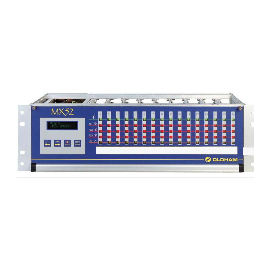
- Page 1 COMMISSIONING, OPERATING MX 52 AND MAINTENANCE MANUAL MEASURING UNIT Part Number: NP52UGB Revision: B.0 The Fixed Gas Detection Experts...
- Page 2 Copyright April 2016 by Oldham S.A.S. All rights reserved. The reproduction of all or any section of this document in any form whatsoever without the written permission of Oldham S.A.S. is forbidden. The information contained in this manual is accurate to our knowledge.
- Page 3 * None of this information may be reproduced, copied, divulged or translated, by physical, electronic or any other means, nor used as the basis for the manufacture or sale of OLDHAM equipment or for any other reasons without prior consent from OLDHAM * This document is not contractually binding.
-
Page 5: Table Of Contents
CONTENTS DESCRIPTION....................7 1.1. General..........................7 1.2. Rack ..........................8 1.3. The various printed circuit boards ................... 8 INSTALLATION AND CONNECTIONS ..........9 .1. Installation: recommendations .................... 9 .2. Electrical connections of the MX52 Unit (Fig. 8) ..............9 2.2.1. Alternative power supply .................. - Page 6 UTILIZATION .................... 27 List and functions of the various items of “USER” equipment for programming and 4.1. calibration of the unit ......................... 27 4.1.1. Keypad (see Figures 26 and 4) ................27 4.1.2. Maintenance keys ....................28 4.1.3. Potentiometers ......................28 4.2.
-
Page 7: Description
The equipment of the MX52 unit comprises line PCBs, each equipped with two channels. However, each channel is independent and can be connected to any type of OLDHAM detector provided that the PCB is suitably programmed. The number of line PCBs is always equal to the mixed even number greater than the number of channels used divided by two. -
Page 8: Rack
One relay common to channels for third thresholds or for all alarms (buzzer transmission), with positive or negative safety, contacts opened or closed at rest One relay common to channels for faults and failures, constant positive safety mode, contacts open or closed at rest. ... -
Page 9: Installation And Connections
Please ensure you read the paragraph: Special Specifications for use in Potentially Explosive Atmospheres in Accordance with European Directive ATEX 94/9/EC Installation: recommendations The MX52 unit can be installed in any premises without an explosive atmosphere. They should preferably be placed in a ventilated and monitored location (guardhouse, control room, instrumentation room, etc.). -
Page 10: Dc Power Supply
2.2.2. DC power supply Voltage: 21 to 30 V continue. The "-" from continue power supply is linked to earth (and earth being linked to frame). Maximum power: 240 W Maximum current in cable: 12.5 A Cable: 2 x 2.5 mm² or 2 x 4 mm² depending on length Location of terminal block: see Fig. -
Page 11: 3-Wire Detectors 4-20 Ma: 3 Connecting Wires For Shielded Cable
2.3.2. 3-wire detectors 4-20 mA: 3 connecting wires for shielded cable Resistance of detector / unit cable: 16 ohms maximum per wire, i.e. 32 ohms in loop (1 km for cable 3 x 1.5 mm²). Connection on MX52 unit: see Fig. 10. 2.3.3. - Page 12 These detectors can operate in standalone mode: 24 V DC power supply and direct utilization of relay contacts in accordance with the technical specification corresponding to the detector used. The current commercial designations are as follows: model 20/20 U - analog - type UV - 752002 (sensitive to UV radiation) model 20/20 UC - analog - type UV (sensitive to UV radiation) model 20/20 UB - µP technology - type UV - 772002 (sensitive to UV radiation) model 20/20 UBC - µP technology - type UV (sensitive to UV radiation)
-
Page 13: Co2 Detector Of Type "Ventostat Vt
REMARK In the case of this application, the maximum of five flame detectors can be connected in the measuring loop. Example of the utilization of IR3 or UV/IR detectors equipped with connectors of type A with a local junction box and galvanic insulation (see Fig. 18). CO2 detector of type “Ventostat VT”... -
Page 14: Other Detectors With Standardized Current Output
Any detector (with 2 wires or 3 wires) that can be supplied with power between 19 V DC and 32 V DC and that supplies a standardized current (signal) of between 4 and 20 mA can be connected to the MX52 unit. The connection requirements are identical to those for the corresponding OLDHAM detectors (see Fig. 22). 2.3.9. -
Page 15: Connecting The Unit To External Devices
Connecting the unit to external devices 2.4.1. Slaving controls The 16 measuring channels of the MX52 unit are each equipped with two relays which can be used to control external devices: sirens, solenoid valves, extractors, telephone calls, etc.. For each measuring channel, the relays are distributed in the following manner (see Fig. 7): a relay associated with the triggering of alarm 1, a relay associated with the triggering of alarm 2, use of open or closed contacts selected with a jumper (see Fig. -
Page 16: Ma Current Outputs (Fig. 12)
2.4.2. 4-20 mA current outputs (Fig. 12) For each measuring channel, the MX52 unit is equipped with a 4-20 mA output that can be used to retransmit measurements to a recorder or an external PLC. The maximum resistance in loop mode is 600 ohms. - Page 17 RS 485 OUTPUT (PINABLE ON FIG 29) Several MX52 units can be linked to a single computer, which is the "master" of the network. In this case, a "SLAVE NUMBER" (by programming/unit) is asigned to each MX52 unit. This RS 485 output can be galvanically insulated as an option. case : no galvanic insulation no mounted insulation component 2 polarization electrical resistances are programmed and welded...
-
Page 18: Remote Acknowledgement
IMPORTANT All details regarding the RS 485 complete description (Modbus / Jbus format, structures, adresses aso…) are developped in a leaflet ref. D 813 577. CAUTION A computer must be used in order to printout the data stored by the MX52 unit. ... -
Page 19: Starting Up
CAUTION OLDHAM is not responsible for the compliance of the complete electrical safety system. The MX52 unit is switched on by means of circuit breakers * provided for that purpose and which ensure protection of the mains power unit. -
Page 20: Operating Modes
Line corresponding to the channel displayed MX 52 v2. when the ENTER key xx LEL CH4 was pressed then *** SELF-TEST *** xx LEL CH4 The user can interrupt the self-test cycle before it is completed by pressing the ACKNOWLEDGEMENT key. - Page 21 In normal operation, a gas alarm is only triggered after a preprogrammed time delay in order to avoid spurious alarms. Alarm thresholds can be processed in the following manners: in normal cycle with manual clearing: block diagram 1, in normal cycle with automatic clearing: block diagram 2, in parking cycle: block diagram 3.
- Page 22 BLOCK DIAGRAM 1 NORMAL CYCLE WITH MANUAL CLEARING START Threshold Illumination of flashing exceeded alarm LED Time T1 Illumination of flashing exceeded alarm LED After T2 time Relay engaged Buzzer engaged Alarm Alarm acknowledged acknowledged LED extinguished LED steady mode Relay disengaged Buzzer stopped Buzzer stopped...
- Page 23 BLOCK DIAGRAM 2 NORMAL CYCLE WITH AUTOMATIC CLEARING START Threshold exceeded Time T1 exceeded Alarm LED illuminated in steady mode After T2 time LED extinguished Relay disengaged Relay engaged Buzzer engaged...
- Page 24 BLOCK DIAGRAM 3 PARKING CYCLE Alarm 3 operates in the same way as the normal cycle. The times defined for alarms 1 and 2 (time delays) are, in this case, used to define the minimum operating time for each relay. t AL1 tR1 R2 t AL2...
-
Page 25: Fault Thresholds
3.3.4. Fault thresholds Processing of detector faults Each channel detects the following faults. For toxic and explosive gas detectors: line interrupted (0 mA), line short-circuited or excessive consumption, negative offset (more than 20% of measuring scale), line in calibration mode (2 mA) (if confirmed by programming). For detectors of the explosive gas type (4-20 mA and 340 mA) in normal mode and if the measurement is greater than 100% of the measuring scale, there are the following immediate results:... -
Page 26: Measuring Unit
3.3.5. Measuring unit One minute after starting up, and if no test action is performed on the keypad, the unit successively scans all the channels in service and displays the measured values. Examples of display Channel 1 x x LEL CH4 Channel 2 x x x ppm CO Each channel is interrogated for 10 seconds. -
Page 27: Utilization
List and functions of the various items of “USER” equipment for 4.1. programming and calibration of the unit 4.1.1. Keypad (see Figures 26 and 4) This is equipped with four touch keys accessible without opening and swivelling the MX52 unit’s FRONT panel or opening and swivelling the FRONT panel for maintenance. -
Page 28: Maintenance Keys
- “Audio and visual” or “audio” clearing of an alarm - Exit from a current menu - Start a self-test manually - VALIDATE 4.1.2. Maintenance keys PROGRAMMING key (item B, Fig. 26): accessible after opening and swivelling the front panel. Combined with the “-”... -
Page 29: Menus
Menus 4.2. 4.2.1. The various menus and their functions The MX52 unit has five menus that are accessed by pressing the “Programming” key (item B, Fig. 26). These five menus are as follows: DESIGNATION FUNCTION “CHANNEL” programming - To program the whole configuration of a measuring channel (ON/OFF, range, alarm thresholds, etc.) “SIMULATION”... - Page 30 SCROLLING OF THE VARIOUS MENUS NORMAL DISPLAY Programming Programming Programming Programming Programming [Channel x x] Simulation Channel xx copy Unit Uploading REMINDER (Fig. 26) Programming key Keys used to move...
-
Page 31: Detailed Flow Diagrams Of Each Menu
4.2.3. Detailed flow diagrams of each menu CHANNEL PROGRAMMING Remove on the programming socket before entering into programming Seuil Alarme 1 NORMAL [25] DISPLAY Programming : last channel displayed [Channel xx] Channel xx [Off] then ENTER : CHOICE OF RANGES Measuring range 100 300 1000 2000 xxxxU... - Page 32 Alarm 3 threshold : 0 to 2000 [75] then ENTER Alarm 1 : Increasing Decreasing [Increasing] then ENTER : Increasing Decreasing Alarm 2 [Increasing] then ENTER : Increasing Decreasing Alarm 3 then ENTER [Increasing] Cycle...
- Page 33 Ack alarm 1 : Manual Automatic [Manual] then ENTER : Manual Automatic Ack alarm 2 then ENTER [Manual] : Time delay Mean Alarm 3 [Time delay] then ENTER : Negative Positive Relay 1 safety ...
- Page 34 Relay 2 safety Negative Positive [Negative] E N T E R then Free Set to 0 Set to 1 Relay 1 E N T E R then [Free] Free Set to 0 Set to 1 Relai 2 ...
- Page 35 The MX52 unit can detect and indicatez (with a flashing Cal detection yellow LED) that a line has-been placed in [No] CALIBRATION mode on the detector. E N T E R then Channel xx Free display: A channel heading can be programmed [Premises 1 channel] U (in 13 characters maximum).
- Page 36 Detector type (Bridge) (4-20 mA) (Fire) [Explosive] : Explosive Toxic Spec. tox. E N T E R then End of menu (1) in case of "Up" fault : 3 "gas" alarms and fault alarm are triggered. (2) In case of "Up"...
- Page 37 LIST OF UNITS DESIGNATION MEANING Lower explosive limit Percent parts per million parts per billion Unter Explosion Grenze (= LEL in German) Limite inférieure d’explosivité (= LEL in French) unit of pressure unit of pressure (millibar) relative humidity metres per second unit of weight (milligram) unit + flashing U free indication of unit...
- Page 38 LIST OF GASES DESIGNATION MEANING Methane Carbon monoxide Hydrogen sulphide Nitrogen Nitric oxide Nitrogen dioxide Sulphur dioxide Chlorine Hydrogen Hydrochloric acid Hydrocyanic acid Ammonia Ethylene oxide Phosphine Hydrofluoric acid Freons Carbon dioxide Arsine Silane SiH4 Butane Propane Natural gas Ethylene Pentane Hexane Propylene...
- Page 39 SIMULATION PROGRAMMING MENU NORMAL DISPLAY Programming [Simulation xx] ENTER Simulation on previously displayed and [validated] channel Programming [Simulation xx] Free labelled area Channel xx S = flashing to indicate that this channel is in LEL CH4 S simulation mode. To artificially vary measurement on the display ...
- Page 40 COPY PROGRAMMING NORMAL DISPLAY Programming Last channel displayed Copy channel xx ENTER Validation of menu Programming Validation of channel to be copied [Copy channel xx] : Copy the channel’s configuration to Copy channel another channel [Channel xx => xx] xx = indication of “Other channel ...
- Page 41 UNIT PROGRAMMING NORMAL DISPLAY Programming Unit ENTER Programming Validation of menu [Unit] Language Choice of languages: [French] : French English German Spanish + then E N T E R Choice of transmission speed with Speed computer: [9600 ] 1200 2400 4800 9600 19200 Bauds ...
- Page 42 This is the time interval between exceeding of the AL threshold and triggering of the corresponding Response time visual alarm (LED). [00 : 00 : 00] Display the time using keys: H mn sec E N T E R then In “Parking”...
- Page 43 UPLOADING PROGRAMMING Only OLDHAM personnel and personnel approved by OLDHAM can be made this operation. **************** ******* Display of menu Validation of utilization of ******* menu ********************* Display of menu **** confirmation ********************* Data transfer request Validation of data transfers...
-
Page 45: Setting The Mx52 Unit Into Service
REMINDER The handling operations and adjustments described in this chapter must be performed by authorized personnel only, as they are liable to affect detection safety. Once the measuring unit has been switched on, it can be programmed (1), its measuring channels can be programmed (1) according to the detectors used and calibrations can be made on the unit and detectors. -
Page 46: Copy
These recommendations are based on safe work procedures, industry best practises, and regulatory standards to ensure worker safety. OLDHAM is not responsible for setting safety practices and policies. * For new installations it may be prudent to carry out bump tests frequently at first (perhaps weekly), increasing the time intervals (to, perhaps, monthly or more) as confidence grows with experience in the installation concerned, on the basis of the maintenance record. - Page 47 REMARK The authorized wind speed is increased to 4.1 m/s when the detector is fitted with a weather protective device. Prepare the measuring channel for calibration: Open and swivel the front panel of the MX52 unit. Manually set the channel to be calculated using keys + and - on the MX52 keypad (item D, Fig.
- Page 48 NOTE For this category of explosive gas detectors, the unit’s display panel indicates 100 DIVISIONS for 100 LEL of an explosive gas. Example: If the reference gas is a 2.5% methane concentration, i.e. 50% LEL of methane, adjust to obtain a display of 50 DIVISIONS.
- Page 49 CAUTION If the detector and the measuring channel are calibrated at the same time, the detector must be left in normal operating mode but the MX52 unit must be set to calibration mode in order to inhibit the relays. Consult the technical manual for the detector concerned. Open the detector (with integrated electronics) in order to gain access to the 4 mA adjustment and sensitivity (20 mA) potentiometers and to the terminals used to check its 4-20 mA output current.
-
Page 50: Ma Output Adjustment For A Measurement Channel
Adjust the detector sensitivity: Inject the calibration gas using the gas injection pipe (or a remote calibrating fixed device) in the same conditions as those applicable for the synthetic air (zero adjustment). When the measurement has stabilized (on the local display panel or on the detector internal terminals (current measurement)), act on the detector’s internal sensitivity potentiometer (see the manual for the detector concerned) in order to set the value (on the detector display panel) corresponding to the concentration of the reference gas or the corresponding current (terminals). -
Page 51: Maintenance
REMINDER The handling operations and adjustments described in this chapter must be performed by authorized personnel only, as they are liable to affect detection safety. Periodic / preventive maintenance 6.1. 6.1.1. On the MX52 unit The MX52 measuring unit requires practically no surveillance. It is, however, recommended that the facilities available on the MX52 unit should be used to regularly test the appliance’s essential functions, as follows: Use the TEST key to check the correct operation of all the LEDs and the buzzer. -
Page 52: Failures: Causes And Remedies
Our company is at your disposal to supply you with standard gas or an annual surveillance contract (preventive maintenance). Under this contract, our specialists guarantee the perfect operation of your installation. No adjustment is to be made between OLDHAM servicing operations. This avoids any additional workload for the user’s maintenance services. - Page 53 Channel in maintenance mode Return the channel to normal for more than 30 minutes. operation by pressing the Calibration key (Item C, Fig. 26). Fault indicator light on (in The measurement is higher To acknowledge the alarm, steady mode) and SUP than 100% of the measuring the measuring channel must displayed.
- Page 54 Faulty electrical connections. Short-circuit or open the relay contact (as applicable) on the MX52 terminal block (Fig. 12) and, if the slaving controls still do not work, the connections must be checked on the MX52 connector and on the slaving systems.
-
Page 55: Scrapping Of Mx52
6112214 Fluorescent display panel 6133521 On/Off switch 6153436 Maintenance screwdriver 6145845 CAUTION It is mandatory that replacement parts must be guaranteed OLDHAM FRANCE original parts as, if this is not the case, the safety of the equipment could be affected. -
Page 87: Detailed Technical Characteristics
MANUFACTURER OLDHAM 62000 ARRAS - FRANCE - Overall dimensions: rack 3U 19” - Function: measuring unit - Capacity: 16 measuring channel - Measurement: continuous - Storage temperature: -20°C to +55°C - Operating temperature: -10°C to +45°C - Relative humidity: 0 to 95% humidity, no condensation... - Page 88 RELAY OUTPUTS - 2 independent measurement alarm relays per channel - 1 common relay for alarm 3 or audio alarm transfer - 1 common fault relay SIGNAL OUTPUTS - 4-20 mA analog per channel, maximum load resistance = 600 - Serial: RS 485 / J BUS , common MISCELLANEOUS OUTPUTS Alarm remote acknowledgement...
-
Page 89: Accordance With European Directive Atex 94/9/Ec
As a result of its metrological performance, as tested by the research and testing organisation INERIS, the MX52 device, is classified as a safety device when used with OLDHAM CEX300 and OLC/OLCT 20, 40, 50 and 60 series detectors. The device may therefore contribute to limiting the risk of explosion as a consequence of the data it supplies to external units. - Page 90 Where the user connects a brand of detector other than OLDHAM to the MX52 device, he must check carefully that the transfer curve is fully compatible with the device input characteristics, to ensure that the data generated by the detector is correctly interpreted.
- Page 91 Where the user connects a brand of detector other than OLDHAM to the MX52 device, he must check carefully that the transfer curve is fully compatible with the device input characteristics, to ensure that the data generated by the detector is correctly interpreted.
- Page 96 Thank you for reading this data sheet. For pricing or for further information, please contact us at our UK Office, using the details below. UK Office Keison Products, P.O. Box 2124, Chelmsford, Essex, CM1 3UP, England. Tel: +44 (0)330 088 0560 Fax: +44 (0)1245 808399 Email: sales@keison.co.uk...
Need help?
Do you have a question about the MX 52 and is the answer not in the manual?
Questions and answers
how to calibrate I trans 2 detector with oldham 52 panel