
Related Manuals for Oldham MX 43


Summary of Contents for Oldham MX 43
- Page 1 MX 43 User Manual Analog and Digital Controller Part Number: NPM43GB Revision: H.1 The Fixed Gas Detection Experts...
- Page 2 Copyright 2013 by Oldham S.A.S. All rights reserved. The reproduction of all or any section of this document in any form whatsoever without the written permission of Oldham S.A.S. is forbidden. The information contained in this manual is accurate to our knowledge.
-
Page 3: Table Of Contents
Chapter 3 │Mechanical Installation ..........7 MX 43 Controller ..................7 Digital Modules .................... 9 Chapter 4 │ The MX 43 Controller ..........11 Overview of the Unit .................. 11 Front Plate ....................15 Alarm and Relay Thresholds ..............18 Firmplate .................... - Page 4 6. USB Key ....................52 Chapter 8 │Main Part Numbers ............ 55 Chapter 9 │Certificate of Compliance .......... 57 Chapter 10 │Technical Specifications ........... 63 MX 43 Controller ..................63 Relay Module..................... 65 16-Logic Input Module ................66 8-Analog Input Module................66 4-Analog Output Module ................
-
Page 5: Chapter 1 │General Information
The aim of this manual is to supply simple and accurate information to the user. Oldham cannot be held liable for any misinterpretations in the reading of this manual. In spite of our efforts to produce an error-free manual, it may nonetheless contain some unintentional technical inaccuracies. -
Page 6: Safety Instructions
Neither Oldham nor any other associated company under any circumstances can be held liable for any damage, including, without limitations, damages for loss or interruption of manufacture, loss of information, defect of the MX 43 controller, injuries, loss of time, financial or material loss, or any direct or... -
Page 7: Chapter 2 │General Introduction
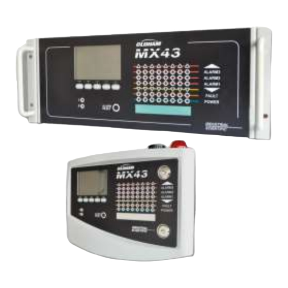
Figure 1: Wall-mounted MX 43 and examples of the modules. The system primarily comprises: ■ a wall-mounted MX 43 (4 or 8 lines) or rack-mounted MX 43 (8 lines); ■ different modules (detector with digital or analog output, logic inputs, analog inputs, relay outputs, and analog outputs). - Page 8 16 logic inputs Module Analog detectors 4 * 4-20 mA outputs 8 analog inputs Analog recorders Figure 2: Example of an MX 43 configuration using different analog and digital detectors as well as digital modules. MX 43 User Manual...
-
Page 9: The Mx 43 Controller
Wall-mounted version 8 lines. ■ Rack-mounted version 8 lines. Figure 3: Wall-mounted version MX 43 (left illustration) or rack- mounted version (right illustration). The following table details the different configurations that are possible, depending on the type of unit. On each line, it is possible to connect a 4-20mA analog detector or one, or several, digitally addressable modules. - Page 10 MX 43 User Manual...
-
Page 11: Chapter 3 │Mechanical Installation
│Mechanical Installation Chapter 3 This chapter details the mechanical installation of MX 43 and the digital modules. MX 43 Controller Location The MX 43 shall be installed in premises without explosive atmospheres, away from direct exposure to sunlight, and protected from humidity, dust, and temperature variations. - Page 12 Use 2 fixing screws 4x25 mm for fixing the case support. Figure 5: Fixing of the wall- mounted version MX 43 with a support plate. Setting-up of a 19” Rack – 4 U Access to the unit must be ensured in order to facilitate adjustments and monitoring, and likewise in the back in order to allow easy access to the different connectors at the rear.
-
Page 13: Digital Modules
Heavy gases are detected close to the ground, while lighter gases are present along the ceiling. If necessary, contact Oldham for any questions regarding proper detector positioning. Fixing The detectors shall preferably be positioned in an accessible place so that inspections and maintenance can be carried out as well as to ensure the absolute safety of the operators. - Page 14 MX 43 User Manual...
-
Page 15: Chapter 4 │ The Mx 43 Controller
Zone 2 status indicator Alarm release key Integrated siren (option) Free identification of zones Integrated flash (optional) Strip for locating zones Lock Handle Start/Stop indicator Figure 8: External view of the wall-mounted and rack-mounted versions. 4 – The MX 43 Controller... - Page 16 A communication failure is signaled by the activation of the internal buzzer, the presence of the orange failure indicator and via the default relay. No digital module active on the line. Optional 24 VDX NiMH battery pack. MX 43 User Manual...
- Page 17 Terminal block for lines 1 to 8 (or 1 to 4 as per version). Refer to the Digital lines paragraph on page 35. Connector for the connection of a remote release (dry contact NO.) Power supply sector input. Protective secondary ground connection. USB programming port. Programming switch. 4 – The MX 43 Controller...
- Page 18 0. MX 43 in normal operation. 1. Transferring configuration from a PC to the MX 43. 2. Transferring configuration from a USB key to the MX 43. 3. Updating the MX 43 internal software via PC. 4. Updating the MX 43 internal software via USB key.
-
Page 19: Front Plate
Microcontroller zero reset button. Press this button to reset the controller. Optional USB key. Allows you to save MX 43 input (measurements, alarms, etc.) or to transfer files from the USB key to the MX 43 (transferring configuration or updates to the MX 43's onboard software). - Page 20 Zone Status Indicators (C) Eight bars of 7 indicators each are displayed on the controller. The 4 bars to the right are not operative on a 4-line MX 43. Each bar represents a geographic area of the complete installation and not the 4 or 8 lines of the MX 43.
- Page 21 Located in the upper portion of the box, the flash is optionally available solely in the wall-mounted version. It is configured via the COM 43 application. Status indicators (F and G) These two indicators reflect the status of the MX 43. Icon Function Green general start/stop indicator denoting the power supply status - Fixed: Correct power supply.
-
Page 22: Alarm And Relay Thresholds
The alarms may be programmed for automatic or manual release (except OVS, UDS, and clear doubt). Automatic deletion of alarms The release (resetting) of alarms does not require any intervention. The management of alarms (relays, indicators, buzzer) is carried out according to the following table: MX 43 User Manual... - Page 23 (failure or alarm). The common failure relay is active in parallel. The sound frequency of the internal buzzer differs in accordance with the alarm threshold. High alarm thresholds have 4 – The MX 43 Controller...
-
Page 24: Firmplate
Z(z), the numbers 0 to 9 and special characters $ % ‘ - _ @ ~ ` ! ( ) { } ^ # & may be used. If other characters are added, the MX 43 will not be able to read the file. - Page 25 The Programming in progress message will appear, followed by Program updated successfully and Transfer successful. Position the programming selector (Figure 10, ref. D) to 0. The MX 43 will then restart using the new uploaded application. Using the MX 43 input files on a PC...
- Page 26 Click on Delimiter > Next > Separator– Comma > Next > Data format – Standard > Finish. Maximize column A. ■ The first 10 lines of the table contain information about the MX 43. ■ Lines Detector name to Last sensor replacement contain information about the configuration of the first sensor.
-
Page 27: Chapter 5 │Digital Modules
│Digital Modules Chapter 5 This chapter presents the digital modules that may be installed on the MX 43 lines. The details of module connection are given on page 33. Digital modules are configured via the COM 43 application. Addressable Digital Modules... -
Page 28: Rs485 Transmission
Terminal (detector, MX 43 module) Figure 16: Principle of connecting modules to a MX 43 line. The incorrect installation of the cables or cable glands can cause measurement errors or a malfunctioning of the system. Do not lay the cables close to equipment such as engines, transformers, or lines generating important magnetic fields. - Page 29 Switches Switches (ON = 1; OFF = 0) (On: 1; OFF: 0) Table 5: Addressing table (address depends on switch positions). Remarks: ■ The physical address of a module (1 to 32) must be identical to the address stated on the configuration program COM 43 in the controller. ■...
-
Page 30: Relay Modules
Factory settings. Do not modify. Remplissage de trame Delay Factory settings. Do not modify. Temporisation E.O.L Resistor See details in paragraph End of line Resistor, on page 25. Résistance F.D.L. Table 6: Relay module configuration switches. MX 43 User Manual... - Page 31 For the 4-relay module, only switches 1 to 4 are active. E – Programmable relays In its maximum configuration, the MX 43 can manage 24 external relays (or 24 modules with 1 stated relay or 3 modules of 8, all stated relays). The relays are individually programmable.
-
Page 32: 16-Logic Input Module
16-Logic Input Module Function This digital module allows the monitoring of 1 to 16 logic inputs by the MX 43. In the 8-line version, the controller can manage a maximum of 32 logic inputs distributed, for example, either on 32... -
Page 33: 8-Analog Input Module
C –Logic input connectors Each of these 16 inputs can be connected to a voltage-free contact as per Figure 39. Input status is transmitted by the digital line to the MX 43. There is no alarm when the contact is closed. - Page 34 V= I (mA) x 0.10 (V/mA) Example: If the current is 12 mA, “V” must be equal to 0.8 V. If point E is not on the module use point G and add 1.2V to the measurement MX 43 User Manual...
-
Page 35: 4-Analog Output Module
This digital module delivers 1 to 4 independent analog values (4-20 mA 2 logic inputs outputs) opto-isolated from the values given by the MX 43, capable of being independently activated or deactivated: ■ Activated: The 4-20mA signal varies depending on the input. - Page 36 E.O.L. Resistor See details in paragraph End of line Resistor, on page 25. Résistance F.D.L. Table 9: Analog output module configuration switches. Connection Refer to Chapter 6, on page 33. Configuration Configured via the COM 43 application. MX 43 User Manual...
-
Page 37: Chapter 6 │Wiring And Electrical Connections
The electrical connections must be carried out by qualified personnel in compliance with the different directives in force in the country of installation. The MX 43 does not have a start/stop switch. Certain voltage levels are capable of causing serious injuries or even death. - Page 38 Figure 28: Connection of sector power in wall-mounted and rack-mounted versions. External 24V DC Power Supply The MX 43 can be powered from a 22 to 28 V AC source at 50/3.2 A, 1.5 A max. In this case, connect the 24VDC source to the corresponding terminal jack (Figure 29, A) respecting polarities.
- Page 39 Figure 30: Positioning the battery pack. Earthing The MX 43 is intended to be used in the parts of installations corresponding to the category of overvoltage II and pollution degree 2 as per EN/IEC 60947-1. In order to comply with this category of protection, it is absolutely necessary to connect the ground terminal (Figure 31, A).
- Page 40 MX 43 terminal block for channel connexion Figure 32: 4-20mA detector connected directly on the MX 43 channels. Please see below the figure for the motherboard with position for channel connection and relays. Figure 33: MX 43 Motherboard. Internal alarm relays...
- Page 41 The dry contacts (nominal resistive load of 2 A at 250 VAC, and 2 A at 30 V DC) of the 6 internal relays R1, R2, R3, R4, R5 and Default are deployed on the MX 43 motherboard on the R1, R2, R3, R4, R5 and Default connectors (Figure 34).
-
Page 42: 4- Or 8-Relay Modules
Supervised Supervised contact contact 4- or 8-output contacts RTC (250VAC or 30 V To MX 43 To next module DC – 2A) or previous module Figure 38: 4- or 8-relay module connections If this module is the last on the line, do not forget to set the switch marked EOL resistor/resistance FDL to ON. -
Page 43: 8-Analog Input Module
8-Analog Input Module To MX 43 To next module or previous module Figure 40: Connections of 8-analog input modules for 1 4-20mA detector with 3 wires (explosive gas, toxicity detection). To MX 43 To next module Wheatstone bridge type or previous module... -
Page 44: 4-Analog Output Module
Output Output 4-20 mA n°2 4-20 mA n°4 To MX 43 To the next module or the previous module Figure 42: 4-analog output module connections. If this module is the last of the line, do not forget to set the jumper switch marked EOL Resistor/FDL resistance to the ON position. -
Page 45: Chapter 7 │Menus
4 MAINTENANCE 5 INFORMATION 6. USB KEY See page 47 See page 48 See page 52 Figure 43: General menu tree of the MX 43. Navigation Key Functions Function Vertical displacement in the selected menu block. Horizontal displacement between two menu blocks. -
Page 46: Display In Normal Mode
Flashing when the key is absent and Data Logging option is set to ON. Indicator of measurement trend Ascending tendency Descending tendency Address of digital detector on a digital line or channel number for a analog detector MX 43 User Manual... -
Page 47: Main Menu
Zone of indication of activated alarms with blinking threshold display. The screen changes to inverse video (Figure 44, screen on the right). Figure 45: Example of a curve display screen. Main Menu This displays all the management menus of MX 43. Figure 46: Main menu. 8 – Main Part Numbers... -
Page 48: System
Screen saver ■ OFF: no screen saver. ■ ON: turns into the screen saver mode (displays Oldham logo) if no key is pressed for a certain period of time. Averaged value ■ OFF: averaged gas measurement value is not displayed. -
Page 49: Program
↑↓ keys. Validate by pressing Enter. Note: Only analog detectors that are not equipped with a local display can be calibrated from the MX 43 controller. For the other detectors, the menu “Sel. Detector” only makes it possible to put them in calibration mode so that they do not activate alarms during their manual calibration. - Page 50 Figure 48: Adjustment of zero (left) and sensitivity (right). Operating mode Detector selection 1. Select the detector to be calibrated with the help of the Previous detector and Next detector keys and press Validate. MX 43 User Manual...
- Page 51 Zero calibration 1. The Zoom command is active. 2. Select the area of interest of the curve with the and keys. Press Zoom + up to the activation of the Zero command. Adjust the position of the cursor so as to make the “OK” appear, in turn indicating that the range selected is sufficiently stable.
-
Page 52: Maintenance
The events log indicates Begin Simulation and End Simulation. ■ Exit the simulation mode by pressing the End simul key. Automatic release then occurs and resets the average values to zero. The current measurements are displayed once more. MX 43 User Manual... -
Page 53: Information
Al2, Al3, Al1mean, Al2mean, Al3mean, OVS), status (activated = ON or deactivated = OFF) as well as the date and time of occurrence or of the release. The letter “S” appears on the line if the events were obtained when the MX 43 was in simulation mode Delete deletes all the data. - Page 54 Table 14: Relay and logic input file messages. 4. Working conditions records This displays the actions carried out on the MX 43 (simulation mode, calibration mode, programming mode, release request, operation on internal battery), as well as the date and time of beginning and end of the event.
- Page 55 Digital module no longer responding (line cut, module failure, wrong address, module absent). MODUL Configuration or module address error. TEMP+ Internal temperature of the MX 43 higher than maximum tolerated value. TEMP- Internal temperature of the MX 43 lower than maximum tolerated value. Switching to external power supply. LINE 1 Incident on line 1 (short-circuit).
-
Page 56: Usb Key
4. Controller info These data allow technicians to visualize MX 43 counters set to zero since the last zero setting. 6. USB Key The USB Key feature is only available in firmware (internal software) versions 4.0 and higher. 1. Configuration Define the recording parameters on the USB key and view the storage capacity remaining. - Page 57 The window displays the following information: ■ Log Files xx of xx (ref. A): the number of Data and Event files that can be opened on the MX 43 screen over the maximum number of files currently saved on the key. ■...
- Page 58 ■ The first file saves the complete configuration of the MX 43 and is called config_JJMMAA_HH_MM.cfg. To view or download this file, set the switch (Figure 10, ref. D) at position 2. See paragraph Transferring configuration to the MX 43 on page 20.
-
Page 59: Chapter 8 │Main Part Numbers
│Main Part Numbers Chapter 8 Description Reference Image MX 43 4-line controller, wall-mounted version 6 514 886 MX 43 8-line controller, wall-mounted version 6 514 884 MX 43 8-line controller, rack-mounted version 6 514 885 Module with 8 analog inputs... - Page 60 6 314 152 RS485 kit 6 314 114 USB Acquisition module with 4G USB Key for wall- 6 314 173 mounted MX 43 USB Acquisition module with 4G USB Key for rack- 6 314 174 mount MX 43 MX 43...
-
Page 61: Chapter 9 │Certificate Of Compliance
│Certificate of Compliance Chapter 9 The document hereafter (1 page) reproduces the EC declaration of conformity. 9 – Certificate of Compliance... - Page 62 MX 43 User Manual...
- Page 63 The document below (1 page) reproduces the 96/98/EC Marine Directive declaration of conformity (followed by the certificate, 2 pages) 9 – Certificate of Compliance...
- Page 64 MX 43 User Manual...
- Page 65 9 – Certificate of Compliance...
- Page 66 MX 43 User Manual...
-
Page 67: Chapter 10 │Technical Specifications
Chapter 10 │Technical Specifications MX 43 Controller Function Function: Gas Detection Controller. Number of lines: 4 or 8 as per model. Display and indicators Display: Back-lit graphic LCD Status indicators: - 7 LEDs for each of the 8 lines, or 56 LEDs. - Page 68 Wall-mounted version: 370 x 299 x 109 mm. ■ Rack-mounted version: 482.8 x 177 x 192.5 mm (19’’, 4 U). See Figure 4 and Figure 6. ■ Weight: Wall-mounted version: 4.0 kg. ■ Rack-mounted version: 2.0 kg. MX 43 User Manual...
-
Page 69: Relay Module
EN61010. CSA: as per C22.2 no.152 (pending). Relay Module Function Function Management of 4 or 8 relays from the digital signals issued by the MX 43. Number of relays: ■ 4 or 8 relays. ■ CRT outputs Relay type: ■... -
Page 70: 16-Logic Input Module
4 bridges -45°C (4 bridges up to 1 km). -50°C (4 bridges up to 500 m). Assembly: Snap-on on DIN rail or mounted on the inside of MX 43. Dimensions: 125 x 165 x 60 mm. MX 43 User Manual... -
Page 71: 4-Analog Output Module
4-Analog Output Module Function Function: Generation of 1 to 4 analog values. ■ Capacity: 4 independent opto-isolated outputs 4-20mA (recopy detector, minimum, maximum, or average of a detector group). Resistance of maximum load 500 . ■ Logic inputs: 2 additional logic inputs (dry contacts). Connections: ■... - Page 72 MX 43 User Manual...
-
Page 73: Chapter 11 | Rs485 Digital Output
Chapter 11 | RS485 Digital Output The MX 43 units using the RS485 Modbus option are equipped with a communication card (code 6314114), which is affixed to the motherboard. This card generates a RS485 output in Modbus RTU format. Card description Figure 52: the RS485 card. -
Page 74: Transfer Table
Access to measurements from the sensor located at line 3 and address 32 of unit n° 2. A. Determination of the sensor address: (3 – 1) x 32 + 32 = 96. B. Structure of the Modbus request: MX 43 User Manual... -
Page 75: Address Table
01 = 0x0001 Thread: 0x01 0x03 0x0A 0x01 0x00 0x01 0xD6 0x21 Address Table Supervision of the MX 43 sensors All reading requests for the Modbus are done via function 3. The cartography is shown below: From addresses 0 to 1999, the Modbus request address serves to select a slave. - Page 76 As a result of the operating functionality, it is only possible to repatriate the data of a single sensor for interrogation. If a sensor is stated at the address mentioned, the MX 43 sends the number of data words requested; always from data #1: NAME OF ANALOG SENSOR, at data #x.
- Page 77 Address SENSORS Data type [256 + 8] bytes 1 Com sensor 2 X 16 Unicode text (16 bits) 16 characters including the final /0. 17 Status Start / Stop: if in operation, variable = 1. If stopped, variable = 0. 18 Gas name 2 x 20 Unicode text (16 bits) 20...
- Page 78 + measurement < alarm. 68 Increasing or Configuration per bit Al 1, 2, 3 instantaneous or decreasing average increasing or alarm? decreasing 1: increasing 0: decreasing Table of registers (below) MX 43 User Manual...
- Page 79 Acquisitions retrieved cyclically Real address SENSOR Data type MEASUREMENTS bytes [256 + 8] Start: 2001 Sensor measurement Table with 264 total 16 bit symbols end : 2264 where the measurements are listed at their address. The measurement being whole, the automatic system uses the Display format field to determine where to position the comma.
- Page 80 The Fixed Gas Detection Experts EUROPEAN PLANT AND OFFICES Z.I. Est – rue Orfila CS 20417 – 62027 Arras Cedex FRANCE Tél: +33 (0)3 21 60 80 80 – Fax: +33 (0)3 21 60 80 00 Website: http://www. .com oldhamgas AMERICAS ASIA PACIFIC EUROPE...
Need help?
Do you have a question about the MX 43 and is the answer not in the manual?
Questions and answers