Table of Contents
Advertisement
Quick Links
Advertisement
Table of Contents

Related Manuals for Oldham BM 25A/AW


Summary of Contents for Oldham BM 25A/AW
- Page 1 BM 25A/AW User Manual Area Gas Monitor Part Number: NP25AEN Version: C.4...
- Page 2 Copyright April 2019 by Oldham Simtronics S.A.S. All rights reserved. The reproduction of all or any section of this document in any form whatsoever without the written permission of Oldham Simtronics S.A.S. is forbidden. The information contained in this manual is accurate to our knowledge.
-
Page 3: Table Of Contents
Contents Chapter 1 | Introduction ............9 General information ..................9 Product Overview ..................10 Additional equipment ................12 Connections ..................... 13 Gas sensors ..................... 15 LCD Display ..................... 16 Visual alarm....................17 Audible alarm ................... 17 Sampling system ..................17 Chapter 2 | Installation and Connections ...... - Page 4 Trickle charging connection (external power source) ......73 Connectors wiring diagram ..............73 ATEX and IECEx Markings ..............74 CSA Hazardous Locations ............... 74 Radio Communication Marking ..............76 Chapter 10 | Declaration of EC Conformity ......77 BM 25A/AW Instruction Manual...
- Page 5 This information shall not, either in whole or in part, by physical, electronic, or any other means whatsoever, be reproduced, copied, divulged, translated, or used as the basis for the manufacture or sale of OLDHAM SIMTRONICS equipment, or for any other reason without the prior consent of OLDHAM SIMTRONICS.
- Page 6 Warnings and cautionary statements This is not a contractual document. In the best interest of its customers and with the aim of improving performance, OLDHAM SIMTRONICS reserves the right to alter the technical features of its equipment without prior notice.
- Page 7 ISA standard 12.13-1 applicable only when the instrument is used in the diffusion mode and has been calibrated to 50% LEL CH4. BM 25A/AW with pump or with PID sensors or with infrared sensors for combustible gases detection is not CSA certified.
- Page 8 BM 25A/AW complies with FCC Maximum Permissible Exposure (MPE) requirements when used with an approved antenna and the antenna is at least 20cm away from the user. Use of the product closer than 20cm may exceed the MPE limits. Use of any antenna other than approved antennas will invalidate the certification of the product.
-
Page 9: Chapter 1 | Introduction
| Introduction Chapter 1 General information The BM 25A/AW is a portable gas monitor that can be used in explosive gas atmospheres. It provides simultaneous detection of up to five gases present in the air by means of sensors specific to each risk to be evaluated (under-oxygenation, presence of combustible or toxic gases). -
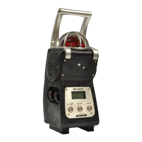
Page 10: Product Overview
Product Overview Figure 2: Product Overview BM 25A/AW Instruction Manual... - Page 11 Ref. Description See page Carrying handle LED alarm indicator (visual warning for gas alarms, transferred alarms and faults) ■ Low Alarm: slow flash (1 Hz) ■ High Alarm: rapid flash (2 Hz) ■ Alarm Transfer: very slow flash (0.5 Hz) ■...
-
Page 12: Additional Equipment
Intrinsically Safe Trickle Charge Kit (provided with cables) Calibration/Sample tubing Communication Adaptor Universal charger 110/230 VAC Cable for IS power supply (see 3) Cable for alarm transfer (25, 50 or 100 meters) (*) Optional BM 25A/AW Instruction Manual... -
Page 13: Connections
Connections Charging port connection (red ring) ■ Connection to Oldham Simtronics universal charger (110/230 VAC) or charger for vehicle (12/30 VDC) ■ Pin 1: V- charge ■ Pin 4: V+ charge Connection prohibited in hazardous area. Unused connectors must be equipped with their protective cap. - Page 14 Dry logic input: Uo = 5 V, Io = 50 mA, Lo = 8 mH, Co = 7 µF The person responsible for the gas monitor must create a Descriptive System Document (for intrinsically safe circuits). BM 25A/AW Instruction Manual...
-
Page 15: Gas Sensors
Gas sensors The sensors are located on the front of the monitor (Figure 2, ref. 10). They are smart, pre-calibrated from factory and interchangeable. They are composed of a sensitive element and electrical components, including an EEPROM memory in which the sensor characteristics are stored (gas type, range, span value, instantaneous, STEL and TWA alarm values, date of manufacture, serial number, date of last calibration, span reserve, etc.). -
Page 16: Lcd Display
Minimum and maximum values (peak) measured ■ STEL (short-term exposure limit) and TWA (time-weighted average) values ■ Remaining battery runtime (bargraph) User’s and/or location’s identification ■ ■ Maintenance menus ■ Alarm events (gas alarm, alarm transfer, sensor fault, battery fault, etc.) BM 25A/AW Instruction Manual... -
Page 17: Visual Alarm
Audible alarm Two powerful speakers (103 dB at 1 meter) located on each side of the BM 25A/AW (Figure 2, ref. 3) alert the user in the event of an alarm. - Page 18 BM 25A/AW Instruction Manual...
-
Page 19: Chapter 2 | Installation And Connections
Insert the male connector (Figure 10, ref. 1) from the charger (ref. 3) into the corresponding charging port and identified with a red ring (ref. 2) on the BM 25A/AW. Connect the other end of the power supply (ref. 4) to the power source. Charging time is 4.5 hours with the 110/230 VAC universal charger. - Page 20 Insert the male connector (Figure 11, ref. 6) from the trickle charger (ref. 1 and 3) into the port with a black ring that is located on the left side of the BM 25A/AW (ref. 4). Connect the other end of the power supply (ref. 2) to the mains and only in areas known to be safe.
-
Page 21: Alarm Transfer
Figure 11: trickle charger connection Alarm Transfer By connecting the output of a BM 25A to the input of another BM 25A, and so on, it is possible to transfer alarms from instruments to instruments. This configuration is particularly useful for perimeter monitoring. For example, it may be used to monitor a fence by connecting the BM 25As on a daisy chain or to monitor a tank by connecting the units in loop. -
Page 22: Connection Of A Manual Call Point
Connection of a manual call point By connecting a manual call point to the input of a BM 25A/AW, it allows the user to fire the local audible and visible alarm in order to alert of an immediate danger (fire, man down, evacuation, etc.). -
Page 23: Chapter 3 | Operation
Chapter 3 Start-up When starting up the BM 25A/AW for the first time or after a period of inactivity longer than one month, it is recommended to proceed a charge- discharge cycle. Moreover, keep in mind that all portable gas monitors must be tested with gas before each day of use. -
Page 24: Gas Monitor Positioning
Test Routine and Calibration Overdue During warm-up the BM 25A/AW performs a self test and then starts gas measurement. If the test is not completed successfully, the BM 25A/AW goes into fault mode (continuous audible and visual signal). When the calibration date for a sensor is overdue, the BM 25A/AW triggers a calibration alert for the appropriate channel. -
Page 25: Aspirated Mode (With Pump Option)
Wait a few seconds before reading the measurements. Any anomaly in the pump system is indicated by an audible alarm and on the LCD display. Figure 15: positioning the sensors cover (BM 25A/AW equipped with an electric pump) 3 – Operation... - Page 26 ■ Place and screw the cover over the sensors (Figure 16: positioning the sensors cover (BM 25A/AW non-equipped with an electric pump)ref. 1); this cover has no hump as previously mentioned (ref. 4). ■ Connect the sample line (ref. 2) to the gas inlet (ref. 3).
-
Page 27: Measurements
Measurements Reading measurements The gas measurements are displayed at once on the LCD display in four separate fields. In each field, the measurement is displayed as follows: ■ Gas concentration ■ Unit (ppm, % vol. or % LEL) ■ Gas type ■... - Page 28 ■ Press Enter to confirm your selection. ■ Press to return to normal mode. Reset the Min/Max Press simultaneously the buttons to reset the min/max values. The BM 25A/AW sounds a beep to confirm the action. BM 25A/AW Instruction Manual...
-
Page 29: Alarms
Alarms The BM 25A/AW features visual and audible indicators: ■ Visual indicators: clear text messages on the display, one 360° red flashlight that is visible from all directions ■ Audible indicators: two loud speakers (103 dB @ 1m) Gas alarms The gas monitor features: ■... - Page 30 Examples of information which may be brought to the user's attention Battery fault ■ Low battery: remaining battery life is less than 20 minutes. The BM 25A/AW is still operating, the audible signal can be silenced. ■ Battery fault: detection is no longer guaranteed. The audible signal cannot be silenced.
- Page 31 By connecting the alarm transfer cable (ref. 2), from the output of a BM 25A (ref. 1) to the input (ref. 3) of another BM 25A, and so on, it is possible to transfer alarms from instruments to instruments. This configuration is particularly useful for perimeter monitoring.
-
Page 32: Data Transfer
(FIFO). Data storage Data are stored as long as internal battery is charged. If the BM 25A/AW is not used for a long period of time and/or main battery is discharged, a lithium battery will take over for a period of two years max. -
Page 33: Switching Off
Switching off ■ To switch the instrument off, press the Enter button (ref. 1) located on the front plate, for 3 seconds. The instrument display starts a countdown from 3 to 1 before it asks to confirm. Release the Enter button (ref. - Page 34 BM 25A/AW Instruction Manual...
-
Page 35: Chapter 4 | Wireless Version
| Wireless Version Chapter 4 This product complies with FCC Maximum Permissible Exposure (MPE) requirements when used with an approved antenna and the antenna is at least 20cm away from the user. Use of the product closer than 20cm may exceed the MPE limits. - Page 36 At least one BM 25AW does Steady Steady not communicate Alarm 1 1 Hz 1 Hz 0.5 Hz 0.5 Hz Alarm 2 2 Hz 2 Hz 0.5 Hz 0.5 Hz Table 1 : ‘Alarm’ mode – Table of events BM 25A/AW Instruction Manual...
- Page 37 Gas alarm Transfer In the event one BM 25AW goes into a gas alarm, all secondary BM 25AWs will display « Al. Transfert » as shown below. Press the “acquit” button to silence the audible alarm. The BM 25AW strobe will continue to flash until the alarm event has ended. The audible alarm will reactivate after 5 minutes if the alarm event is still active.
- Page 38 The alarm sequence differs depending on whether a BM 25AW sends information (gas alarm or fault) or receives information (alarm transfer). This allows for quick identification of the BM 25AW that is in alarm so that appropriate action can be taken. BM 25A/AW Instruction Manual...
-
Page 39: Start-Up
Main BM 25AW Secondary BM 25AW Controller Case Cause Flash Siren Flash Siren Channel status Fault (no Steady Fault communication at all, sensor fault, low battery, etc.) Alarm 1 1 Hz 1 Hz 0.5 Hz 0.5 Hz Alarm 1 Alarm 2 2 Hz 2 Hz 0.5 Hz... - Page 40 When in BM 25 mode, BM 25AW displays the radio signal strength as indicated below in figure 27c. It corresponds to the average of signals received from all BM 25AWs that the BM 25AW you are looking at is communicating with. BM 25A/AW Instruction Manual...
- Page 41 Figure 27c – BM 25 mode : Radio Signal Strengh When is displayed, the BM 25AW has 100% of the signal and the radio communication is very good. When is displayed, the signal strengh is less than 20% although BM 25AWs are still communicating.
-
Page 42: Self-Healing
In BM 25 mode, if a BM 25AW does not respond or if the network is split, then it is possible to ignore this fault and to continue to work by the time of the restoration of the network. BM 25A/AW Instruction Manual... - Page 43 In the example above, BM 25AW (unit D) is the only communication link between A, B, C and E, F, G. If BM 25AW (unit D) had a fault (low battery for instance) or if an obstacle were to disrupt communication between D and E or D and B, then all BM 25AWs would report a fault failure (steady flashlight according to case No.
- Page 44 Adding a new BM 25AW to the network at a smart location overcomes the obstacle and restores the communication between the two groups which then merge together. This healing is automatic as long as BM 25AW (unit H) belongs to the same network (same 'Channel' ID). BM 25A/AW Instruction Manual...
-
Page 45: Mac List Menu
Figure 31 : bypassing an obstacle by adding a new BM 25AW (H) Mac list menu NOTE : This section covers the BM 25 mode only. Available from the Maintenance menu (see Chapter 5), the « MAC List » menu allows the user from any BM 25AW belonging to the network to get the MAC address of each BM 25AW on the network and its particular status. - Page 46 When a BM 25AW is no longer communicating on the network, its address appears in reverse video. See “SELF-HEALING” parapragh for trouble shooting. Figure 35 : BM 25AW with MAC address No. 0487D1 does not communicate BM 25A/AW Instruction Manual...
-
Page 47: Chapter 5 | Maintenance
These recommendations are consistent with applicable industry safety protocols and with the standards and directives relative to the safety of industrial sites. OLDHAM SIMTRONICS is also not responsible for procedures performed onsite. The gas monitor is factory-programmed to display a maintenance alert if a calibration has not been performed in the last twelve months (the message Calibration due will appear on the screen). -
Page 48: Program Menu
If the combustible gas to be detected is not in this list, you can use the Other window by selecting a coefficient provided by OLDHAM SIMTRONICS (contact us). -
Page 49: Sensor Calibration Menu
Molecular Vapor Coef. / Recom- Abbreviation formula density mended (French) calgas Acetone 2.15 % 13 % But/Prop Acetylene 1.5 % 100 % But/Prop Butane 1.5 % 8.5 % 2.13 But/Prop Ethanol 3.3 % 19.0 % But/Prop Ethylene 2.7 % 34.0 % 0.98 But/Prop ... -
Page 50: Auto-Adjustment Menu
When battery is low, the user is notified with a Battery fault message before losing all stored data. The battery must then be replaced. This operation should only be performed by OLDHAM SIMTRONICS or OLDHAM SIMTRONICS approved personnel. Radio communication menu This menu allows the user to: ■... -
Page 51: Chapter 6 | Com2100 Software
Calibration and Control certificates ■ Datalogging management Through its infrared port (ref. 1), the BM 25A/AW can be connected to a computer by using a connection cable (ref. 2 and 3). Figure 36: interconnection cable and welcome screen 6 – COM2100 software... -
Page 52: Gas Monitor Connection
Gas monitor connection Once COM 2100 is running, the BM 25A/AW connects automatically and a window pops up as indicated in figure Figure 37: the parameter programming menu. Follow the steps below: ■ Set communication parameters as necessary (port, speed, language) ■... - Page 53 Programming Menu Proceed as follows: ■ From the Maintenance menu (Figure 38), select Programming ■ The screen here below pops up Figure 39 - Program menu screen Channel settings ■ Access is password protected. The default code is 1000 (to change this code, see paragraph Screen menu on page 58).
- Page 54 Once have confirmed calibration is complete, the BM 25A/AW will notify whether the sensor passed failed Figure 42: confirming Calibration calibration. In the event of a failure, repeat the calibration process or proceed with sensor replacement. BM 25A/AW Instruction Manual...
- Page 55 Oldham Simtronics recommends using pure gases: using mixed gases can alter the accuracy of gas measurements due to cross interferences between the sensors. The calibration gas concentration value shall be between 15% and 100% of the measurement range. Date and Time Settings ■...
- Page 56 Step 1 Step 2 and 3 Step 4 Status Report menu From the Maintenance menu (Figure 38: Maintenance menu) select ’State card’ and follow the same steps as described in the Monitoring Report menu (.etx files). BM 25A/AW Instruction Manual...
-
Page 57: Alarm Relay Configuration And Logic Inputs
To set the BM 25A/AW modes when logic input is activated (set to 1). Alarm relay: internal relay output is activated Alarm 1: BM 25A/AW will turn in Alarm 1 mode Alarm 2: BM 25A/AW will turn in Alarm 2 mode... -
Page 58: Screen Menu
‘>’ (>>) icon. ■ To remove an user/location from the BM 25A/AW, select an input from the right and click on the ‘<’ (>>) icon. Figure 46: list of users/locations ■ Click OK to confirm. BM 25A/AW Instruction Manual... -
Page 59: Chapter 7 | Technical Specifications
| Technical Specifications Chapter 7 Gas monitor Function Manufacturer : OLDHAM SIMTRONICS Function: Area Gas Monitor Type: BM 25A and BM 25AW (wireless) Configuration: One to four sensors (catalytic, electrochemical, infrared or PID sensors) Gases detected: Combustible, toxic and oxygen... - Page 60 CE, ATEX, IECEx, CSA , FCC BM 25A/AW with pump or with PID sensors or with infrared sensors for combustible gases detection is not CSA certified. CSA certification does not include wireless communication used for combustible gas performance. The wireless communication may only be used for data collection or record keeping with regard to combustible gas detection.
-
Page 61: Sensors
Sensors Non-exhaustive list. Table No. 1 Methane (CH Methane (CH Propane (C 6313969 Sensor P/N 6314064 6313969 0 - 100% LEL Standard range (1) 0 - 100% LEL CH4 0 - 100% LEL CH4 C3H8 Infrared Measurement principle Catalytic (not CSA certified) Display resolution(1) 1% LEL 1% LEL... - Page 62 6 months ■ ■ 3 months 3 months maximum Warm-up Delay (10) Operational upon start up ■ Presence of high levels of CO can lead to ■ Notes 10.6ev lamp an over estimation of O concentration. BM 25A/AW Instruction Manual...
- Page 63 Table no. 3 Carbon dioxide Carbon Monoxide Hydrogen sulfide (CO) Sensor P/N 6313818 6313787 6313788 Standard range (1) 0 - 5% v/v 1000 Absorption Measurement principle Electrochemical Electrochemical Infrared Display resolution(1) 0.1% v/v Accuracy (2) 0.2% v/v Repeatability (3) 0.1% v/v Zero/Span drift (4) 0.2 / 2 0.5 / 1.5...
- Page 64 ■ Exposure to high levels of organic solvents can damage the sensors. ■ Notes Exposure to gases at levels higher than the monitor’s range can damage the device. Recalibrate sensors if they go out of range. BM 25A/AW Instruction Manual...
- Page 65 Table no. 5 Ammonia Ammonia Nitrogen oxide (NO) Sensor P/N 6313799 6313800 6313802 Standard range (1) 1000 Measurement principle Electrochemical Electrochemical Electrochemical Display resolution(1) Accuracy (2) Repeatability (3) Zero/Span drift (4) 1 / 2 1 / 2 0.5 / 3 lowest recommended 10ppm 30ppm...
- Page 66 11. at 20°C. TWA and STEL values depend on the country of use and might be lower. It is your responsibility to check the product suits your application. Other gases, other ranges: consult us at info@Oldham Simtronicsgas.com BM 25A/AW Instruction Manual...
-
Page 67: Accessories And Spare Parts
| Accessories and Spare Chapter 8 Parts Accessories Description Part Number Universal charger 110/230 VAC for BM 25A/AW - Charging time 6511157 4.5hrs 6511164 Vehicle charger 12/30 VDC for BM 25A/AW WCHMUBM Wall charger for BM 25A/AW 6321390 Support for BM 25A/AW wall charger... -
Page 68: Spare Parts
NO sensor 0-300 ppm sensor – 0-2000 ppm 6313803 6313804 HCl sensor 0-30.0 ppm 6313805 HCN sensor 0-30.0 ppm 6313806 HF sensor 0-10 ppm 6313807 sensor (Ozone) 0-1 ppm 6313808 sensor (Silane) 0-50 ppm 6313809 sensor 0-10.0 ppm BM 25A/AW Instruction Manual... - Page 69 6313810 sensor (Phosphine) 0-1 ppm 6313811 sensor (Arsine) 0-1 ppm 6313812 COCl sensor (phosgene) 0-1 ppm 6313820 sensor 0-1 ppm 6313879 sensor 0-1ppm 6313841 sensor 0-3 ppm MEDIUM sensors (fit slot #5 only) 6313998 PID isobutylene sensor 0-1500 ppm 6314065 sensor IR 0-100% LEL (4.4%vol) 6314064 sensor IR 0-100% LEL (5.0%vol)
- Page 70 BM 25A/AW Instruction Manual...
-
Page 71: Chapter 9 | Special Instructions For Use In Explosive Atmospheres Or Hazardous Locations
- Cable - Body is Intrinsically Safe (see standard IEC 60079-25 for the preparation of this document). The BM 25A/AW complies with the following standards: ATEX IECEx Canadian Electrical Code EN 60079-0:2012/A11:2013 IEC 60079-0 (ed. -
Page 72: Atex Areas And General Rules
Input/output parameters Gas monitor recharge connector The charger provided by OLDHAM SIMTRONICS should only be used outside of the ATEX areas. When the recharging is done by a charger other than the one provided by OLDHAM SIMTRONICS, its characteristics must not exceed a voltage of 30VDC and a current of 30 A. -
Page 73: Trickle Charging Connection (External Power Source)
Alarm relay output and dry logic input connectors Input characteristics for the alarm relay output: ■ = 30 V max. ■ = 150 mA max. Output characteristics for the dry logic input: ■ = 5 V. ■ = 50 mA. ■... -
Page 74: Atex And Iecex Markings
Warning: Potential electrostatic charging hazard – see instructions CSA Hazardous Locations The drawing in following page defines the CSA approved electrical parameters permitted for the interconnection of the BM 25A/AW to other circuits or apparatus while the instrument is situated in a hazardous location BM 25A/AW... - Page 75 CSA Control Drawing for BM 25A/AW Connections 9 – Special Instructions...
-
Page 76: Radio Communication Marking
Class I Zone 1, AEx d ia IIC T4 (For US Only) C22.2 No. 152 (%LEL only) BM 25A/AW with pump or with PID sensor or with infrared sensor for combustible gases detection is not CSA certified. CSA certification does not include wireless communication used for combustible gas performance. -
Page 77: Chapter 10 | Declaration Of Ec Conformity
| Declaration of EC Chapter 10 Conformity The document hereafter (2 pages) reproduces the EC declaration of conformity. 10 – Declaration of EC Conformity... - Page 78 BM 25A/AW Instruction Manual...
- Page 79 10 – Declaration of EC Conformity...
- Page 80 EUROPEAN PLANT AND OFFICES Z.I. Est – rue Orfila - CS 20417 – 62027 ARRAS Cedex FRANCE Tél.: +33 (0)3 21 60 80 80 – Fax: +33 (0)3 21 60 80 00 Web site: http://www.Oldham Simtronicsgas.com AMERICAS ASIA PACIFIC EUROPE Tel.
Need help?
Do you have a question about the BM 25A/AW and is the answer not in the manual?
Questions and answers