Table of Contents
Advertisement
Advertisement
Table of Contents

Related Manuals for Oldham BM25


Summary of Contents for Oldham BM25
- Page 1 BM 25/25W User Manual Area Gas Monitor Part Number: NPB25EN Version: L.2...
- Page 2 Copyright Mars 2016 by Oldham S.A.S. All rights reserved. The reproduction of all or any section of this document in any form whatsoever without the written permission of Oldham S.A.S. is forbidden. The information contained in this manual is accurate to our knowledge.
-
Page 3: Table Of Contents
Contents Chapter 1 | Introduction ............9 General information ..................9 Product Overview ..................10 Additional equipment ................12 Connections ..................... 13 Gas sensors ..................... 15 LCD Display ..................... 16 Visual alarm....................17 Audible alarm ................... 17 Sampling system ..................17 Chapter 2 | Installation and Connections ...... - Page 4 Sensor calibration menu ................50 Auto-adjustment menu ................50 Date and time management menu ............50 Radio communication menu ..............50 MAC List menu ..................50 Exit menu ....................50 Chapter 6 | COM2100 software ..........51 Subject ..................... 51 Gas monitor connection ................
- Page 5 The extent of our responsibility ■ OLDHAM shall not be held responsible for any damage to the equipment or for any physical injury or death resulting in whole or in part from the inappropriate use, installation, or storage of the equipment, which is the result of not complying with the instructions and warnings, and/or with the standards and regulations in force.
- Page 6 Warnings and cautionary statements This is not a contractual document. In the best interest of its customers and with the aim of improving performance, OLDHAM reserves the right to alter the technical features of its equipment without prior notice. IMPORTANT: Failure to perform certain procedures or note certain conditions may impair the performance of this product.
- Page 7 CAUTION: For safety reasons, this equipment must be operated and serviced by qualified personnel only. Read and understand the instruction manual completely before operating or servicing. CAUTION: High off-scale readings may indicate explosive concentration. CAUTION: Any rapid up-scale reading followed by a declining or erratic reading may indicate a gas concentration beyond the upper scale limit which may be hazardous.
- Page 8 BM 25/25W Instruction Manual...
-
Page 9: Chapter 1 | Introduction
| Introduction Chapter 1 General information The BM 25/25W is a portable gas monitor that can be used in explosive gas atmospheres. It provides simultaneous detection of up to five gases present in the air by means of sensors specific to each risk to be evaluated (under-oxygenation, presence of combustible or toxic gases). -
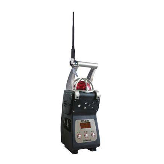
Page 10: Product Overview
Product Overview Figure 2: Product Overview BM 25/25W Instruction Manual... - Page 11 Ref. Description See page Carrying handle LED alarm indicator (visual warning for gas alarms, transferred alarms and faults) ■ Low Alarm: slow flash (1 Hz) ■ High Alarm: rapid flash (2 Hz) ■ Alarm Transfer: very slow flash (0.5 Hz) ■...
-
Page 12: Additional Equipment
Additional equipment Figure 3: accessories Ref. Description See page Sensors Cover for use with aspirated versions (*) Calibration cup for use with manual sampling system or for sensors calibration Intrinsically Safe Trickle Charge Kit (provided with cables) Calibration/Sample tubing Communication Adaptor Universal charger 110/230 VAC Cable for IS power supply (see 3) Cable for alarm transfer (25, 50 or 100 meters) -
Page 13: Connections
Connections Charging port connection (red ring) ■ Connection to Oldham universal charger (110/230 VAC) or charger for vehicle (12/30 VDC) ■ Pin 1: V- charge ■ Pin 4: V+ charge Connection prohibited in hazardous area. Unused connectors must be equipped with their protective cap. - Page 14 Relay Outputs (black ring) ■ Pins 1-6: alarm relay (NO) output ■ Pins 3-4: fault relay (NC) output Unused connectors must be equipped with their protective cap. See details on pages 21 and 57. Figure 6: relay outputs Dry logic inputs (yellow ring) ■...
-
Page 15: Gas Sensors
Gas sensors The sensors are located on the front of the monitor (Figure 2, ref. 10). They are smart, pre-calibrated from factory and interchangeable. They are composed of a sensitive element and electrical components, including an EEPROM memory in which the sensor characteristics are stored (gas type, range, span value, instantaneous, STEL and TWA alarm values, date of manufacture, serial number, date of last calibration, span reserve, etc.). -
Page 16: Lcd Display
Note: ■ If a sensor is present in slot #5, then sensor in slot #2 is not monitored The “combo” CO/H ■ S sensor can only be plugged in slot #4 ■ The PID sensor can only be plugged in slot #5 Sensor slots and protection filters must be kept clean. -
Page 17: Visual Alarm
Visual alarm A red bright flashlight (Figure 2, ref. 2) visible from all direction is located on the top of the device and alerts the user in the event of an alarm. Audible alarm Two powerful speakers (103 dB at 1 meter) located on each side of the BM 25/25W (Figure 2, ref. - Page 18 BM 25/25W Instruction Manual...
-
Page 19: Chapter 2 | Installation And Connections
| Installation and Chapter 2 Connections Power supply General Information Power is supplied to the gas monitor through an interchangeable and rechargeable battery pack (NiMH 7.2 V / 9 Ah). Under normal usage conditions and no radio communication, the battery life ranges from 40 to 170 hours depending on the configuration (100 hours under typical configuration: diffusion mode with 1 catalytic or 1 infrared sensor and 2 electrochemical sensors). - Page 20 (catalytic, infrared, PID) or when the pump is continuously running. Only intrinsically safe power supplies provided by OLDHAM can be used. Insert the male connector (Figure 11, ref. 6) from the trickle charger (ref. 1 and 3) into the port with a black ring that is located on the left side of the BM 25/25W (ref.
-
Page 21: Alarm Transfer
Figure 11: trickle charger connection Alarm Transfer By connecting the output of a BM 25 to the input of another BM 25, and so on, it is possible to transfer alarms from instruments to instruments. This configuration is particularly useful for perimeter monitoring. For example, it may be used to monitor a fence by connecting the BM 25s on a daisy chain or to monitor a tank by connecting the units in loop. -
Page 22: Connection Of A Manual Call Point
Connection of a manual call point By connecting a manual call point to the input of a BM 25/25W, it allows the user to fire the local audible and visible alarm in order to alert of an immediate danger (fire, man down, evacuation, etc.). -
Page 23: Chapter 3 | Operation
Before displaying current measurements, the BM 25/25W performs visual and audible tests during a few seconds and then displays: - The OLDHAM logo, - The software revision and the serial number, - The alarm thresholds set for each measurement channel. -
Page 24: Gas Monitor Positioning
Step 1: Switch the instrument on ■ Press and hold the Acquit button (ref. 1). Press the Enter button (ref. 2) to switch the instrument on. ■ Release both buttons. ■ When warm-up is complete, the BM 25/25W displays the list of different gases. The gas currently selected is highlighted. -
Page 25: Aspirated Mode (With Pump Option)
Aspirated mode (with pump option) Remote sensing is possible with the internal electric pump option, or by using a hand aspirator. Sampling probes (rigid, semi-rigid or telescopic) and sampling tubing are not antistatic. The user must take the necessary precautions to avoid electrostatic discharges. - Page 26 Before each use of the electrical pump, check the seal by obstructing the end of the sampling line until the Flow Fault alarm is triggered. Do not forget to remove the sensors cover to return to diffusion mode. Using a manual pump Figure 16: positioning the sensors cover (BM 25/25W non-equipped with an electric pump) ■...
-
Page 27: Measurements
Measurements Reading measurements The gas measurements are displayed at once on the LCD display in four separate fields. In each field, the measurement is displayed as follows: ■ Gas concentration ■ Unit (ppm, % vol. or % LEL) ■ Gas type ■... - Page 28 Displaying additional information When the gas monitor is in normal operation, the user can access additional information. Press the button repeatedly to scroll through the following screens: ■ Date (backlit is ON) ■ Area identification or user name (only if Roundsman option is activated; see paragraph Roundsman function, below) ■...
-
Page 29: Alarms
Alarms The BM 25/25W features visual and audible indicators: ■ Visual indicators: clear text messages on the display, one 360° red flashlight that is visible from all directions ■ Audible indicators: two loud speakers (103 dB @ 1m) Gas alarms The gas monitor features: ■... - Page 30 Unlatching Alarms In this configuration, audible and visual alarms will be acknowledged automatically, without any action, as long as the gas measurement is within the set limits. Fault alarms Faults can be classified into two categories: ■ Sensor faults: out of range, low sensitivity, zero drift, etc. ■...
- Page 31 By connecting the alarm transfer cable (ref. 2), from the output of a BM 25 (ref. 1) to the input (ref. 3) of another BM 25, and so on, it is possible to transfer alarms from instruments to instruments. This configuration is particularly useful for perimeter monitoring.
-
Page 32: Data Transfer
These parameters are mentioned in the paragraph Special Instructions for use in explosive atmospheres on page 71. OLDHAM shall not, in any event, be liable for failure to follow regulations. Data transfer The BM 25/25W stores gas measurements, alarm and fault events. -
Page 33: Switching Off The Instrument
Switching off the instrument ■ To switch the instrument off, press the Enter button (ref. 1) located on the front plate, for 3 seconds. The instrument display starts a countdown from 3 to 1 before it asks to confirm. Release the Enter button (ref. - Page 34 BM 25/25W Instruction Manual...
-
Page 35: Chapter 4 | Wireless Version
| Wireless Version Chapter 4 This product complies with FCC Maximum Permissible Exposure (MPE) requirements when used with an approved antenna and the antenna is at least 20 cm away from the user. Use of the product closer than 20 cm may exceed the MPE limits. - Page 36 Two-way communication Figure 21 : In the example above, BM 25W tag G communicates with E and F. In the event of a loss of communication between G and F, E still ensures the communication to the rest of the network. If G goes into gas alarm or fault condition, all BM 25Ws on the network will report a corresponding alarm Alarm sequence differs depending on whether a BM 25W sends information (gas alarm or fault) or receives information (alarm transfer).
- Page 37 Gas alarm Transfer In the event one BM 25W goes into a gas alarm, all secondary BM 25Ws will display « Al. Transfert » as shown below. Press the “acquit” button to silence the audible alarm. The BM 25W strobe will continue to flash until the alarm event has ended. The audible alarm will reactivate after 5 minutes if the alarm event is still active.
- Page 38 Controller Mode In Controller mode, BM 25Ws send fault status, alarm status and gas measurements to the controller. As soon as one BM 25W fires an alarm, the controller relays the gas alarm information to all BM 25Ws on the same network that then turn in Alarm Transfer mode.
-
Page 39: Start-Up
Main BM 25W Secondary BM 25W Controller Case Cause Flash Siren Flash Siren Channel status Fault (no Steady Fault communication at all, sensor fault, low battery, etc.) Alarm 1 1 Hz 1 Hz 0.5 Hz 0.5 Hz Alarm 1 Alarm 2 2 Hz 2 Hz 0.5 Hz... - Page 40 ■ It is important that all BM 25Ws intended to be on the same network have the same network ID. ■ In Controller mode, two BM 25Ws cannot share the same address otherwise you will get a fault. Once wireless mode is activated (‘BM 25’ or ‘Controller’ mode), you have 5 minutes to declare another BM 25W on the same network.
- Page 41 Figure 27c – BM 25 mode : Radio Signal Strengh When is displayed, the BM 25W has 100% of the signal and the radio communication is very good. When is displayed, the signal strengh is less than 20% although BM 25Ws are still communicating.
-
Page 42: Self-Healing
Self-healing NOTE : This section covers the ‘BM 25’ mode only. Each BM 25W broadcasts a message every 10 seconds. Using the example shown below, if BM 25W tag A receives no message from BM 25W tag B for more than 2 minutes, then B is considered as missing by A which turns into fault mode (case No. - Page 43 In the example above, BM 25W (unit D) is the only communication link between A, B, C and E, F, G. If BM 25W (unit D) had a fault (low battery for instance) or if an obstacle were to disrupt communication between D and E or D and B, then all BM 25Ws would report a fault failure (steady flashlight according to case No.
- Page 44 25Ws on the network and forces to a new identification. Similarly as above, BM 25Ws (units E, F and G) form a second group. IMPORTANT : ■ The two groups run independently and alarm or failure events from one group cannot be transferred to the other group.
-
Page 45: Mac List Menu
Figure 31 : bypassing an obstacle by adding a new BM 25W (H) Mac list menu NOTE : This section covers the BM 25 mode only. Available from the Maintenance menu (see Chapter 5), the « MAC List » menu allows the user from any BM 25W belonging to the network to get the MAC address of each BM 25W on the network and its particular status. - Page 46 When in the « MAC List » menu, the first address displayed and aligned to the right is the address of the BM 25W you are currently looking at (here 0487D2). Up to 6 MAC addresses can be displayed per page. Figure 33 : List of the MAC addresses present on the network A BM 25W in gas alarm mode is shown with the status ‘A’...
-
Page 47: Chapter 5 | Maintenance
These recommendations are consistent with applicable industry safety protocols and with the standards and directives relative to the safety of industrial sites. OLDHAM is also not responsible for procedures performed onsite. The gas monitor is factory-programmed to display a maintenance alert if a calibration has not been performed in the last twelve months (the message Calibration due will appear on the screen). -
Page 48: Program Menu
If the combustible gas to be detected is not in this list, you can use the Other window by selecting a coefficient provided by OLDHAM (contact us). BM 25/25W... - Page 49 Molecular Vapor Coef. / Recom- Abbreviation formula density mended (French) calgas Ethyl acetate 2.1 % 11.5 % 1.35 But/Prop Acetone 2.15 % 13 % 1.55 But/Prop Acetylene 1.5 % 100 % But/Prop Butadiene 1.4 % 16.3 % 1.85 1.25 But/Prop Butane 1.5 % 8.5 %...
-
Page 50: Sensor Calibration Menu
Expected lithium battery’s runtime is 2 years. When battery is low, the user is notified with a Battery fault message before losing all stored data. The battery must then be replaced. This operation should only be performed by OLDHAM or OLDHAM approved personnel. Radio communication menu This menu allows the user to: ■... -
Page 51: Chapter 6 | Com2100 Software
| COM2100 software Chapter 6 Subject This software is for settings and service purpose. It features: ■ Channels settings ■ Diagnostics in case of failure ■ Instrument settings ■ Sensors calibration ■ Calibration and Control certificates ■ Datalogging management Through its infrared port (ref. 1), the BM 25/25W can be connected to a computer by using a connection cable (ref. -
Page 52: Gas Monitor Connection
Gas monitor connection Once COM 2100 is running, the BM 25/25W connects automatically and a window pops up as indicated in figure Figure 37: the parameter programming menu. Follow the steps below: ■ Set communication parameters as necessary (port, speed, language) ■... - Page 53 Programming Menu Proceed as follows: ■ From the Maintenance menu (Figure 38), select Programming ■ The screen here below pops up Figure 39 - Program menu screen Channel settings ■ Access is password protected. The default code is 1000 (to change this code, see paragraph Screen menu on page 58).
- Page 54 Reference Gas settings ■ Access is password protected. Select the channel fitted with the catalytic sensor (Channel selection, see Figure 39). ■ Select the Reference Gas as necessary: Choose another gas from the list and click on Programming combustible gas (Figure 40: programming combustible Figure 40: programming gas.
- Page 55 Oldham recommends using pure gases: using mixed gases can alter the accuracy of gas measurements due to cross interferences between the sensors. The calibration gas concentration value shall be between 15% and 100% of the measurement range. Date and Time Settings ■...
- Page 56 Example: Step 1 Step 2 and 3 Step 4 Status Report menu From the Maintenance menu (Figure 38), select ’State card’ and follow the same steps as described in the Monitoring Report menu (.etx files). BM 25/25W Instruction Manual...
-
Page 57: Alarm Relay Configuration And Logic Inputs
Alarm relay configuration and logic inputs ■ Set relay output and the logic input by checking the different boxes (Figure 45). Reference 1 Alarm relay output settings. In this example all CO, O2 and LEL alarms will trigger the relay output. Reference 3 To set the BM 25/25W modes when logic input is activated (set to 1). -
Page 58: Screen Menu
Screen menu This menu displays the log events, gas measurements and device’s configuration. The password to access the maintenance menu is 0018 and software access code is 1000. Those passwords are user configurable. Lists of users and/or locations can be created from this menu. This function allows to assign log events by user or location. -
Page 59: Chapter 7 | Technical Specifications
| Technical Specifications Chapter 7 Gas monitor Function Manufacturer : OLDHAM Function: Area Gas Monitor Type: BM 25 and BM 25W (wireless) Configuration: One to four sensors (catalytic, electrochemical, infrared or PID sensors) Gases detected: Combustible, toxic and oxygen Measurement:... - Page 60 ■ Sensor fault: Visual and Audible alarm (continuous) ■ Clear message on the display ■ Battery fault: Visual and Audible alarm (continuous) ■ Clear message on the display Inputs and outputs ■ Inputs/Outputs RS232 infrared link ■ Alarm relay output ■...
-
Page 61: Sensors
Sensors Non-exhaustive list. Table No. 1 Methane Methane Methane Sensor reference 6314064 6313888 6313889 Standard range (1) 0 - 100% LEL CH4 0 - 100% LEL CH4 0 - 100% vol Measurement principle Infrared Catalytic Catharometric Display resolution(1) 1 % LEL 1 % LEL 1% v/v Accuracy (2) - Page 62 Table No. 2 Oxygen Oxygen Isobutylene ) 2 years ) 1 year Sensor P/N 6313998 6313780 6313817 0 – 1500ppm 2 – 30% volume Standard range (1) 2 - 30% volume isobutylene Measurement principle Electrochemical Electrochemical Display resolution(1) 1ppm 0.1% v/v 0.1% v/v Accuracy (2) 0.3% v/v...
- Page 63 Table no. 3 Carbon dioxide Carbon Monoxide Hydrogen sulfide (CO) Sensor P/N 6313818 6313787 6313788 Standard range (1) 0 - 5% v/v 1000 Absorption Measurement principle Electrochemical Electrochemical Infrared Display resolution(1) 0.1% v/v Accuracy (2) 0.2% v/v Repeatability (3) 0.1% v/v Zero/Span drifty (4) 0.2 / 2 0.5 / 1.5...
- Page 64 Table No. 4 Chlorine Hydrochloric acid Hydrogen cyanide (HCl) (HCN) Sensor P/N 6313809 6313804 6313805 Standard range (1) Measurement principle Electrochemical Electrochemical Electrochemical Display resolution(1) Accuracy (2) 0.25 0.25 Repeatability (3) Zero/Span ndrift (4) 0.5 / 5 0.5 / 5 0.5 / 5 Response time (5) <...
- Page 65 Table no. 5 Ammonia Ammonia Nitrogen oxide (NO) Sensor P/N 6313799 6313800 6313802 Standard range (1) 1000 Measurement principle Electrochemical Electrochemical Electrochemical Display resolution(1) Accuracy (2) Repeatability (3) Zero/Span drift (4) 1 / 2 1 / 2 0.5 / 3 Response time (5) <...
- Page 66 Table No. 6 Nitrogen dioxide Sulfur dioxide Sensor P/N 6313801 6313819 Standard range (1) Measurement principle Electrochemical Electrochemical Display resolution(1) Accuracy (2) Repeatability (3) Zero/Span drift (4) 0.5 / 5 0.5 / 2 Response time (5) < 30s < 60s Temperature (6) -20°C to +40°C -20°C to +50°C...
-
Page 67: Chapter 8 | Accessories And Spare Parts
| Accessories and Spare Chapter 8 Parts Accessories Description Part Number Universal charger 110/230 VAC for BM 25/25W - Charging time 6511157 4.5hrs 6511164 Vehicle charger 12/30 VDC for BM 25/25W WCHMUBM Wall charger for BM 25/25W 6321390 Support for BM 25/25W wall charger WLOGUSB COM 2100 software kit with infrared/USB cable 6314588... -
Page 68: Spare Parts
Part Number Description Intrinsically Safe Trickle charger with two IS power supplies and BM25KITCHD25 25 meters of IS cable Intrinsically Safe Trickle charger with two IS power supplies and BM25KITCHD50 50 meters of IS cable Intrinsically Safe Trickle charger with two IS power supplies and BM25KITCHD100 100 meters of IS cable Alarm transfer kits... - Page 69 6313800 sensor 0-1000 ppm 6313801 sensor 0-30 ppm 6313802 NO sensor 0-300 ppm sensor – 0-2000 ppm 6313803 6313804 HCl sensor 0-30.0 ppm 6313805 HCN sensor 0-30.0 ppm 6313806 HF sensor 0-10 ppm 6313807 sensor (Ozone) 0-1 ppm 6313808 sensor (Silane) 0-50 ppm 6313809 sensor 0-10.0 ppm 6313810...
- Page 70 BM 25/25W Instruction Manual...
-
Page 71: Chapter 9 | Special Instructions For Use In Explosive Atmospheres Or Hazardous Locations
| Special Instructions for Chapter 9 use in explosive atmospheres or hazardous locations Information in following paragraphs must be taken into account and followed by the person responsible for the equipment installation site. Refer to the provisions of European ATEX Directive 1999/92/EC or to the applicable local legislation, relevant to improving safety protection and health of workers exposed to the risks of explosive atmospheres. -
Page 72: Atex Areas And General Rules
The charger provided by OLDHAM should only be used outside of the ATEX areas. When the recharging is done by a charger other than the one provided by OLDHAM, its characteristics must not exceed a voltage of 30VDC and a current of 30 A. -
Page 73: Trickle Charging Connection (External Power Source)
Alarm relay output and dry logic input connectors Input characteristics for the alarm relay output: ■ = 30 V max. ■ = 150 mA max. Output characteristics for the dry logic input: ■ = 5 V. ■ = 50 mA. ■... -
Page 74: Atex And Iecex Markings
ATEX and IECEx Markings BM 25 (without radio communication module) OLDHAM CE 0080 BM 25 IP 66 Ambient T: -20° C +55° C II 1G/ I M1 Ex ia IIC T4 Ga / Ex ia I Ma With infrared sensor block IP 66 Ambient T: -20°... -
Page 75: Radio Communication Marking
Radio Communication Marking Contains RF200 FCC ID : U9O-RF200 Contains RF200 IC : 7084A –RF200 This device complies with Part 15 of FCC Rules. Operation is subject to the following two conditions: (1) This device may not cause harmful interferences, and (2) this device must accept any interference received, including interference that may cause undesired operation. - Page 76 BM 25/25W Instruction Manual...
-
Page 77: Chapter 10 | Declaration Of Ec Conformity
| Declaration of EC Chapter 10 Conformity The document hereafter (2 pages) reproduces the EC declaration of conformity. 10 – Declaration of EC Conformity... - Page 78 BM 25/25W Instruction Manual...
- Page 79 10 – Declaration of EC Conformity...
- Page 80 The Fixed Gas Detection Experts EUROPEAN PLANT AND OFFICES Z.I. Est – rue Orfila - CS 20417 – 62027 ARRAS Cedex FRANCE Tél.: +33 (0)3 21 60 80 80 – Fax: +33 (0)3 21 60 80 00 Web site: http://www.oldhamgas.com AMERICAS ASIA PACIFIC EUROPE...
Need help?
Do you have a question about the BM25 and is the answer not in the manual?
Questions and answers