Table of Contents
Advertisement
Quick Links
Advertisement
Table of Contents

Subscribe to Our Youtube Channel
Related Manuals for First Degree Fitness UB-E920


Summary of Contents for First Degree Fitness UB-E920
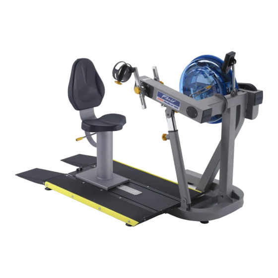
- Page 1 USER GUIDE UB - E920 Wheelchair Accessible...
-
Page 2: Safety
Training with the E920 Congratulations on your purchase of E920. FIRST DEGREE FITNESS is proud to present the Rower as a FULL COMMERCIAL USE product featuring patented Adjustable Fluid Resistance. As with any piece of fitness equipment, consult a physician before beginning your E920 exercise program. - Page 3 Contents Safety ................... 4 Assembly - UB-E920 ............... 6 UB-920 Box 1 & 2 Contents ............ 7 Assembly Instructions ............. 8 Operation Instructions ............... 13 Maintenance ................18 Troubleshooting ................19 Tank Belt Adjustment ..............20 International Warranty ............21...
-
Page 4: Safety Information
Safety Safety Information • Before using this product, it is essential to read this ENTIRE operation manual and ALL instructions. The Rower is intended for use solely in the manner described in this manual. • UNDERSTANDING EACH AND EVERY WARNING TO THE FULLEST IS IMPORTANT •... - Page 5 Inspection • DO NOT use or permit use of any equipment that is damaged and/or has worn or broken parts. For all FIRST DEGREE FITNESS equipment use only replacement parts supplied by FIRST DEGREE FITNESS. • EQUIPMENT MAINTENANCE - Preventative maintenance is the key to smooth operating equipment as well as to keep your liability to a minimum.
-
Page 6: Product Specifications
Assembly - UB-E920 Product Specifications Product Class: SC Braking System: Speed Independent Product Net Weight: 90kg (198lb) Product Gross Weight: 110kg (242lb) Maximum Safe Operating Surface Area: 301cm (108.27”) Length x 222cm (87.40”) Width Dimensions: 1810mm (71.26”) Length x 1020mm (40.16”) Width x 148mm (58.27”) Height... - Page 7 UB-E920 Box 1 & 2 Contents Item Qty. Description Item Qty. Description Main Frame with Telescoping Tube Foot Levelers and Internal Gas Assist Shock Baseplate Handle Bar & Nut Dome Head Seat Frame Funnel and Hose Seat Back Touch up paint...
-
Page 8: Assembly Instructions
Assembly Instructions STEP 1 Mainframe Assembly Instructions REQUIRED Attach Telescoping Tube to the underside of the 4 x M8 x 15mm Blots [7] control arm using 4x M8x15mm Bolts[7] and 4x M8 Spring Washers[17]. 4 x M8 Spring Washers [17] b) Thread the 3x Foot levelers[18] into underside of base. - Page 9 Assembly Instructions STEP 3a Installing Baseplate to the Mainframe REQUIRED T-Track Ramp Right T-Track Ramp Left 2 x PVC Side Covers 3 x M10x20mm Blots [11] 2 x M10 Nylock Nut [13] PVC Side Covers Ramp Right 3 x M10 Washer [16] Ramp Left Bolt the T-Track to the Mainframe as shown, using Remove contents from box...
- Page 10 Assembly Instructions STEP 3b Installing Baseplate to the Mainframe REQUIRED Attach Left and Right Ramps to the T-Track using 8x M8x45mm Bolts[10]. 4 x M8 x20mm Bolts [8] 4 x M8 x25 Blots [9] c) Once the Left and Right Ramps have been installed to the sides of the T-Track, secure the front end of each 8 x M8 x45mm Blots [10] Ramp as shown using 4x M8x25 Bolts[9], 4x M8...
- Page 11 Assembly Instructions STEP 4 Installing Seat Assembly Thread the Handle Bar[19] through the Shaft REQUIRED Seat Frame [3] Tighten the Handle Bar[19] with the M10 Dome Nut[13]. Seat Back [4] Install Seat Back[4] with 4x M6x20 Bolts[6] and M6 Lower Seat [5] Washer[14].
- Page 12 Assembly Instructions STEP 5 Installing Seat to the Mainframe Seat Stop: Must be lowered to allow seat onto CAUTION Baseplate track. Must ALWAYS be in the LOCKED position when seat is occupied on Baseplate. Must The Seat Stop Must be in the locked position whenever be lowered to allow seat removal.
-
Page 13: Operation Instructions
Operation Instructions E920 Control Arm Chain Tensioning Bolts: Allows for tightening the chain or adjustment from side to side. Make sure when tightening only to adjust the same amount for both bolts, otherwise the sprocket will be misaligned. Note: Tightening the right bolt only (turning clockwise) will pull the right side of the crank assembly toward you, tightening the left will pull the left side toward you. - Page 14 Operation Instructions Slider Arm Kit Installation Instructions Mount the left Slider Arm onto the Axle using the yellow indicator hole to align the slider and axle. Tighten the set screw onto the Axle and into the yellow indicator hole using the 3mm Allen key.
- Page 15 Operation Instructions Additional Exercises Training can now be achieved with both left and right Handgrips moving parallel , rather than in an opposed motion. a) On the right Slider Arm Assembly, remove the Adjustment Knob, loosen set screw and remove Assembly from the Axle.
-
Page 16: Tank Filling And Water Treatment
Operation Instructions Tank Filling and Water Treatment REQUIRED Filling requires a large bucket (not Supplied) and the supplied Funnel and Hose [20] water Funnel and Hose[20]. Filling will take approximately 8 liters of water. Open the yellow fill plug on the back of the tank and insert hose CAUTION (rotating the impeller slightly may be necessary to allow the Use a drop cloth under... -
Page 17: Using The First Degree Fitness Usb Interface
Note: For complete operational instructions, please refer to the computer manual, which is included with your Rower. Using the First Degree Fitness USB Interface Description: The USB connectivity now built in to all new models of FDF Console and IPM allow you to enhance your exercise experience by connecting to your home PC or Laptop. - Page 18 First degree fitness equipment. First degree fitness is not responsible for performing regular inspection and maintenance actions for your machines. Instruct all personnel in equipment inspection and maintenance actions and also in accident reporting and recording.
-
Page 19: Troubleshooting
Troubleshooting Fault Probable Cause Solution Water changes color Rower is in direct Change rower location to reduce direct or becomes cloudy. sunlight or has not exposure to sunlight. Add water treatment had water treat- or change tank water as directed in the ment. -
Page 20: Tank Belt Adjustment
Tank Belt Adjustment 1. Remove large metal inspection plate. 2. Using a long tool, push out the rear end cap as pictured below left. This will give you access to the tank End Cap 4. Using a 6mm Allen Key, tighten the 3. -
Page 21: International Warranty
Metal Frame – 10 Year Limited Warranty First Degree Fitness will repair or replace the metal Main Frame should it fail due to any defect in materials or workmanship within 10 years of the original purchase. Warranty does not apply to frame coating. - Page 22 CONTACT US For customer support please visit firstdegreefitness.com/support TAIWAN T: +886 3 478 3306 764 Chung Shan South Rd Yangmei Taoyuan Taiwan R.O.C.
Need help?
Do you have a question about the UB-E920 and is the answer not in the manual?
Questions and answers