Advertisement
Quick Links
Temperature PID controller TCY-MT-U
TCY-MT-U Intelligent temperature PID controller
Features
Temperature PID control for HVAC systems.
Up to 2 modulating outputs for DC 0...10V with 10mV resolution.
1 internal temperature sensor and up to 2 external sensor inputs
Multiple remote control functions on external input
Password protected programmable user and control parameters
Blue backlight
Applications
Various temperature control applications
Stand alone VAV control for pressure independent actuators
Water Only Systems: Radiator, floor heating or chilled ceilings
Individual room control for offices, residential, hotel rooms, meeting rooms, etc.
General description
The TCY-MT-U is a stand-alone electronic universal controller with one temperature control loop. It may use
up to 2 PID sequences. The TCY-MT-U features 1 internal NTC temperature sensor, one external sensor,
one binary input and one analog output. The configuration has been reduced to a minimum to allow for a
simple and off the shelve usage. For more advanced features and current in- and outputs the TCI product
range is recommended. The TCY-MT-U can be configured using the standard operation terminal. No special
tool or software is required.
TCY-MT2-U
│ │││ └──── Housing:
U = Vertical (2" x 4") housing, Standard is square housing
│ ││└────── Function:
2 = 2-pipe, 4 = 4-pipe
│ │└─────── Input
T = Temperature
│ └──────── Output:
B = Binary
└──────────Series Indication
TCY
Item Name
Item code
Variant
Features
TCY-MT2-U-W01
40-10 0044-01
Cooling only
Compact PID controller with:
TCY-MT2-U-W02
40-10 0044-02
Heating only
2 TI, 1 AO
TCY-MT2-U
40-10 0044
2-Pipe system
TCY-MT4-U
40-10 0046
4-Pipe system
1 TI, 2 AO
Accessories
S-Tn10-2
40-20 0001
Flying lead sensor with 2 m cable
SD-Tn10-12-2
40-20 0002
Flying lead duct sensor 12cm immersion depth, 2m cable
SD-Tn10-20-2
40-20 0003
Flying lead duct sensor 20cm immersion depth, 2m cable
SDB-Tn10-12
40-20 0051
Duct sensor with housing, 12cm immersion depth
SDB-Tn10-20
40-20 0004
Duct sensor with housing, 20cm immersion depth
SOA-Tn10
40-20 0006
Outdoor sensor
Selection of actuators and sensors
Use only our approved NTC sensors to achieve maximum accuracy. Recommended is SDB-Tn10-20 as
Duct sensor, SRA-Tn10 as Room sensor and SDB-Tn10-20 with AMI-S10 as immersion sensor.
Modulating Actuators:
Choose actuators with an input signal type of 0-10V DC or 2-10V DC.
Mounting location
On an easy accessible interior wall, approx. 1.5 m (4.5') above the floor in an area of
average temperature.
Avoid exposure to direct sunlight or other heat sources, e.g. the area above radiators and
heat emitting electrical equipment.
Avoid locations behind doors, outside walls and below or above air discharge grills and
diffusers.
Location of mounting is less critical if external temperature sensors are used
Installation
1.
Connect the wires to be connected to the terminals of the power case according to wiring
diagram
2.
Install the mounting plate to the flush mounting box. Make sure that the nipple with the front
holding screw is facing to the ground. Make sure the mounting screw heads do not stand out
more than 5 mm (0.2") off the surface of the mounting plate.
3.
Ensure that the jumpers are set correctly.
4.
Slide the two latches located on the top of the front part into the hooks at the upper side of
the mounting plate.
5.
Carefully lower the front part until the interconnector reaches the mounting-plate. Continue
pressing in a gentle way until the front part is fully connected. While inserting the connectors,
a slight resistance can be felt. This is normal. Do not use excessive force!
6.
With a Philips-type screw driver of size #2, carefully tighten the front holding screw to secure
the front part to the mounting plate. This screw is located on the front lower side of the unit.
There is no need to tighten the screw too much.
Doc: 70-00-0177-20, V1.2 20160119
Temperature PID controller TCY- MT-U
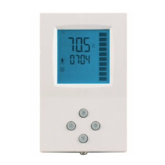
Display and operation
Mode
Display of operation mode
Indicators
1 Remote temperature
sensor
2 Dew point sensor
Up: Increment SET POINT
(Parameter setting:
SCROLL menu options and
parameters)
Left (POWER): Press < 2 sec.: Toggle
STANDBY-COMFORT mode or switch
from OFF to ON
Press > 2 sec.: Turn unit OFF. Text OFF
displayed with current time (deluxe)
temperature (standard)
(Parameter setting: ENTER to select
menu option, accept parameter change)
Power failure
Upon power-interruption, all parameters and set points are memorized in non-volatile memory and therefore do not
have to be re-entered again.
Error messages
Err1:
The connection to the temperature sensor may be interrupted or the temperature sensor is damaged.
The output is switched off. Verify parameter settings and wiring.
Technical specification
Power Supply
Operating Voltage
24 V AC/DC ± 10 %, 50/60 Hz, Class 2 48VA max
Power Consumption
Max. 1.5 VA
Electrical Connection
Terminal Connectors,
wire 0.34...2.5 mm
Signal inputs
Temperature Input
0...50 °C (32...122 °F)
Range
Accuracy
0.5 K
Signal outputs
Analog Outputs
AO1, For TCY-MT4 AO2
Output Signal
DC 0...10 V
Resolution
9.76 mV (10 bit)
Maximum Load
10 mA
Environment
Operation
To IEC 721-3-3
Climatic Conditions
class 3 K5
0...50 °C (32...122 °F)
Temperature
Humidity
<95 % r.H. non-condensing
Transport & Storage
To IEC 721-3-2 and IEC 721-3-1
Climatic Conditions
class 3 K3 and class 1 K3
-25...70 °C (-13...158 °F)
Temperature
Humidity
<95 % r.H. non-condensing
Mechanical Conditions
class 2MT2
Standards
conform according
to
EN 61 000-6-1/ EN 61 000-6-3
EMC Standard
89/336/EEC
EMEI Standard
73/23/EEC
Product standards
EN 60 730 –1
Automatic electrical controls for
household and similar use
EN 60 730 – 2 – 9
Special requirement on temperature
dependent controls
Degree of Protection
IP30 to EN 60529
Safety Class
III (IEC 60536)
Housing
Cover, back part
Fire proof ABS plastic (UL94 class V-0)
Mounting Plate
Galvanized Steel
General
Front part: 112 x 73 x 15 mm (4.4" x 2.9" x 0.6")
Dimensions (H x W x D)
Power case: ø 58 x 32 mm (ø 2.3" x 1.3")
Weight (including package)
270 g (9.5 oz)
© Vector Controls GmbH, Switzerland
Wiring diagram
Large Digits: Display of input
or parameter value.
24V AC
Small Digits: Display of set
point, clock or parameter
number.
Vertical Bar: (scrolls
up/down, 10% resolution)
Right (OPTION):
Press < 2 sec.: Select Control Loop
Press > 2 sec.: Manual H/C change
0V (COM)
(Parameter setting: ENTER to
select menu option, accept
parameter change)
24V AC
Down: Decrement SET POINT
(Parameter setting: SCROLL menu
options and parameters)
0V (COM)
Description:
G0
G
M
X1
2
(AWG 24...12)
TCY-MT2:
X2
U1
TCY-MT4:
U1
U2
Dimensions [mm] (in)
Temperature PID controller TCY- MT-U
X
X
T CO
T EXT
2
5 6
7 8
G
M
X2
M
X1
1
34
TCY-MT2-U
G0
G0U1
Y
M1
X
T EXT
2
7 8
G
M
X1
1
34
5 6
TCY-MT4-U
G0
G0U1
G0U2
Y
Y
M H
M C
Power supply:
0V, -24VDC, internally connected to signal common
Power supply:
24VAC, +24VDC
Signal common:
Common 0 potential for analog inputs and analog outputs.
External temperature input: NTC 10kΩ @ 25°C (77°F)
NTC 10kΩ @ 25°C (77°F)
Changeover input:
0...10 V DC
Analog output:
0...10 V DC
Analog heating output:
0...10 V DC
Analog cooling output:
73 (2.9)
32 (1.2)
15
(0.6
)
Subject to alterations
Advertisement

Related Manuals for Vector TCY-MT2-U-W01


Summary of Contents for Vector TCY-MT2-U-W01
- Page 1 Front part: 112 x 73 x 15 mm (4.4” x 2.9” x 0.6”) Dimensions (H x W x D) Power case: ø 58 x 32 mm (ø 2.3” x 1.3”) Weight (including package) 270 g (9.5 oz) Doc: 70-00-0177-20, V1.2 20160119 © Vector Controls GmbH, Switzerland Subject to alterations...
- Page 2 TCY-MT2: 0 - 2 TCY-MT2-W01: 0 is pressed for more than 5 minutes. TCY-MT4: 0 – 3 TCY-MT2-W02: 1 0 = TCY-MT2-U-W01 = Cooling mode Y CP18 = 0 External control The control input is provided by the external input. The TCY-MT2:...
Need help?
Do you have a question about the TCY-MT2-U-W01 and is the answer not in the manual?
Questions and answers