Table of Contents
Advertisement
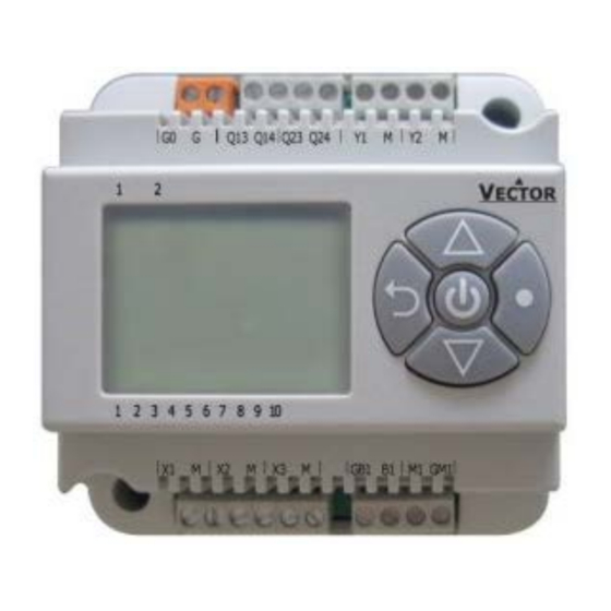
TCI-C Series cabinet mounted universal controller
Applications
•
Air Only Systems: Constant or variable air volume systems for single or dual duct systems with options of:
up to two reheat stages
o
supply air, extract air cascade control
o
humidity control
o
Control for variable speed fans
o
•
Air/Water Systems:
Fan Coil units for 2-pipe or 4-pipe systems with options of:
o
radiator control, chilled ceiling
o
•
Water Only Systems: Radiator, floor heating or chilled ceilings
•
Individual room control for hotel rooms, meeting rooms, etc.
General Description
The TCI-C is a stand-alone cabinet mounted electronic universal controller with two autonomous control loops. Each
control loop may use up to 2 PID sequences and 6 binary sequences. The TCI-C11 features 1 independent control loop, 2
universal inputs, 2 binary outputs and one analog output, the TCI-C22 offers 2 independent control loops, 3 universal
inputs, 1 PT1000 input, 2 binary relays outputs and 2 analog outputs. A detailed configuration is possible by following a
simple setup routine. The TCI can be configured using the standard operation terminal. No special tool or software is
required.
Name
- C
T
C
I
2
2
Doc: 70-00-0123, Date: 20091020
Humidity control
Pressure control
-
0
Supply Voltage 0 = 24VAC, 1 = 110VAC, 2 = 230VAC
In/Outputs:
Control loops:
Housing:
Series:
© Vector Controls GmbH
TCI-C-Universal Controller
Features
•
Universal PID and binary control for any analog
input/output signal and range
•
2 independent control loops with each 2 PID sequences and
6 independent binary sequences
•
2 modulating output for DC 0...10V or 0...20 mA actuators
with 10 bit resolution.
•
3 universal inputs for NTC 10k, open contact binary input,
DC 0...10V or 0...20 mA sensors with 10 bit resolution
•
1 PT1000 input -50...200°C (-58...392°F)
•
Multiple auxiliary functions: heat – cool auto changeover,
remote control, setpoint compensation
•
Cascading of control loops
•
Alarm monitoring of low and high limits on all inputs.
Programmable reaction in case of alarm.
•
Feedback function for inputs and set points.
•
Special functions for dehumidifying, set point shift and VAV
control
•
Password protected programmable user and control
parameters
•
Deluxe Version only:
Power Cap protected real time clock with 24h power
o
backup
8 time schedule events, with many options
o
Blue backlight
o
1 = 2UI, 2DOR, 1AO, 2 = 1PT1000, 3UI, 2DOR, 2AO
1 = 1 control loop, 2 = 2 control loops
C = Cabinet, W = Wall mounted
TCI
Page 1
Advertisement
Table of Contents

Related Manuals for Vector TCI-C Series


Summary of Contents for Vector TCI-C Series
- Page 1 TCI-C-Universal Controller TCI-C Series cabinet mounted universal controller Features • Universal PID and binary control for any analog input/output signal and range • 2 independent control loops with each 2 PID sequences and 6 independent binary sequences • 2 modulating output for DC 0...10V or 0…20 mA actuators with 10 bit resolution.
-
Page 2: Technical Specifications
Fire proof ABS plastic (UL94 class V-0) General Dimensions (H x W x D) 60 x 93 x 93(110*) mm (2.4” x 3.7” x 3.7(4.3*)”) Din rail mounting Weight (including package) 240 g (8.5 oz) Doc: 70-00-0123, Date: 20091020 © Vector Controls GmbH Page 2... -
Page 3: Dimensions [Mm] (Inch)
Actuators with constant running time are recommended. Observe power limits on binary devices. Binary auxiliary devices: E.g. pumps, fans, on/off valves, humidifiers, etc. Do not directly connect devices that exceed 250 VAC, 8(5) A. Observe startup current on inductive loads. Doc: 70-00-0123, Date: 20091020 © Vector Controls GmbH Page 3... -
Page 4: Connection Diagram
0…250 VAC or 0…30 VDC Binary output 2: 0…250 VAC or 0…30 VDC Analog output 1: 0…10 V or 0…20 mA Analog output 2: 0…10 V or 0…20 mA ) selectable by jumper Doc: 70-00-0123, Date: 20091020 © Vector Controls GmbH Page 4... -
Page 5: Display And Operation
Clock: Operation modes may automatically be switched according to daytime and weekday. The clock symbol will be indicated if time programs are activated. • Via inputs, by using auxiliary functions parameters. Doc: 70-00-0123, Date: 20091020 © Vector Controls GmbH Page 5... -
Page 6: Standard Display
An assigned input is not enabled or missing. All control loops, functions and outputs tied to this input will be disabled. Verify input connections, jumper settings and parameter settings for the input involved. Doc: 70-00-0123, Date: 20091020 © Vector Controls GmbH Page 6... -
Page 7: Accessing Advanced Settings
Outputs must be set in manual mode in order to be controlled by time schedule! Access to time schedules may be disabled with UP04 Doc: 70-00-0123, Date: 20091020 © Vector Controls GmbH Page 7... -
Page 8: Setting Of Parameters
= Reset of override mode is not active. Time schedules can be overridden manually. 1…255 = delay in minutes to switch off device if ON/Economy mode is activated while the unit is scheduled to be in OFF mode Doc: 70-00-0123, Date: 20091020 © Vector Controls GmbH Page 8... -
Page 9: Control Functions
Winter Compensation Summer Compensation 1L04 1L02 FU01 = ON FU04 = ON Fu04 = OFF 1L01 FU01 = OFF 1L03 T [°C, F] U [V, mA] FU06 FU02 FU03 FU05 Doc: 70-00-0123, Date: 20091020 © Vector Controls GmbH Page 9... -
Page 10: Pid Control
TI = 60s, KI = 0.4 For dehumidifying systems: TI = 70s, KI = 0.3 Pressure Control (VAV): TI = 1s, KI = 0.8 (depending on speed of actuator KI varies) Doc: 70-00-0123, Date: 20091020 © Vector Controls GmbH Page 10... -
Page 11: Binary Control
Delayed switching. Cumulative Heating/ cooling stages will not switch simultaneously with stage 1, in case of a sudden demand or at power on. Stage 2 will not start earlier than 5 seconds after stage 1 has been initiated. Doc: 70-00-0123, Date: 20091020 © Vector Controls GmbH Page 11... -
Page 12: Universal Input
The TCI-Cx-2x includes a PT1000 temperature input. The input works with a standard PT1000 probe between -50…200°C (-58…392°F). Accuracy is within 0.5°C for the entire range. It is recommended to use a three or four wire sensor to compensate for wire resistance. Doc: 70-00-0123, Date: 20091020 © Vector Controls GmbH Page 12... -
Page 13: Auxiliary Functions
Heat-cool changeover based Heat and cool state of the controller may as well be determined by the state of one of on demand of one control its control loops. loop Doc: 70-00-0123, Date: 20091020 © Vector Controls GmbH Page 13... -
Page 14: Alarm Function
Values of universal inputs as well as set points of control loops may be transmitted on the feedback analog outputs. Minimum and maximum value of the feedback value may be set for each output. Doc: 70-00-0123, Date: 20091020 © Vector Controls GmbH Page 14... -
Page 15: Binary Outputs
Switching difference on floating output: Use the Switching difference parameter to reduce the switching frequency of the actuator. The actuator will only move, if the difference to the current actuator position is larger than this parameter. Doc: 70-00-0123, Date: 20091020 © Vector Controls GmbH Page 15... -
Page 16: Configuration Of Controller
10. Press the LEFT key again so as to leave the parameter menu and return to the group selection. Press LEFT key again while in the group selection to return to normal operation. 11. The unit will return to normal operation if no key is pressed for more than 5 minutes. Doc: 70-00-0123, Date: 20091020 © Vector Controls GmbH Page 16... -
Page 17: Digital Control Sequence
Delay for heat – cool changeover in case above parameter is OFF 1L 24 0…255 min 5 min Doc: 70-00-0123, Date: 20091020 © Vector Controls GmbH Page 17... -
Page 18: Temperature Input Configuration
OFF = Not active ON = Active 1t 08 Alarm 8 high limit of temperature input -40…215 °C 50°C (122°F) 1t 09 Alarm 8 Hysteresis for alarm setback 0…100 ° 5°C (10°F) Doc: 70-00-0123, Date: 20091020 © Vector Controls GmbH Page 18... - Page 19 Fu 17 Change Over limit to activate function Range acc input Fu 18 Change Over limit to deactivate function Range acc input Fu 19 Disable in case of alarms Selection Doc: 70-00-0123, Date: 20091020 © Vector Controls GmbH Page 19...
-
Page 20: Analog Output
0% Alarm: 1 2 3 4 5 6 7 8 1A 08 Feedback function: minimum input value Acc input 0°C 1A 09 Feedback function maximum input value Acc input 100°C Doc: 70-00-0123, Date: 20091020 © Vector Controls GmbH Page 20... - Page 21 Choose alarm to set output to 0%. In case of conflicting alarms, the output Selection will be set to 0% Alarm: 1 2 3 4 5 6 7 8 1d 08 Display Fan Symbol while active ON, OFF Doc: 70-00-0123, Date: 20091020 © Vector Controls GmbH Page 21...
Need help?
Do you have a question about the TCI-C Series and is the answer not in the manual?
Questions and answers