Table of Contents
Advertisement
Quick Links
See also:
User Manual
Advertisement
Table of Contents

Subscribe to Our Youtube Channel
Related Manuals for Sunny Health & Fitness SF-B2640


Summary of Contents for Sunny Health & Fitness SF-B2640
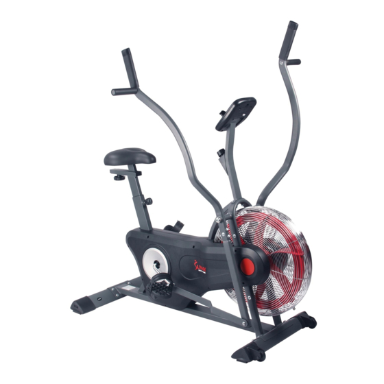
- Page 1 AIR BIKE TRAINER SF-B2640 USER MANUAL IMPORTANT! Please retain owner’s manual for maintenance and adjustment instructions. Your satisfaction is very important to us, PLEASE DO NOT RETURN UNTIL YOU HAVE CONTACTED US: support@sunnyhealthfitness.com or 1- 877 - 90SUNNY (877-907-8669).
-
Page 2: Important Safety Information
IMPORTANT SAFETY INFORMATION We thank you for choosing our product. To ensure your safety and health, please use this equipment correctly. It is important to read this entire manual before assembling and using the equipment. Safe and effective use can only be assured if the equipment is assembled, maintained, and used properly. It is your responsibility to ensure that all users of the equipment are informed of all warnings and precautions. -
Page 3: Exploded Diagram
EXPLODED DIAGRAM... -
Page 4: Hardware Package
HARDWARE PACKAGE #100 OD12xID8.5xT2.0 4PCS #72 OD25xID13x1.5 4PCS #69 OD16xID8.5x1.5 4PCS #99 OD20xID8.5xT1.5 4PCS #77 OD20xID10.5xT1.5 1PC #95 OD21*ID14*T0.3 4PCS #63 OD26xID16.2x2.0 2PCS #71 M8x7.5xS13 4PCS #96 M8x10xS5 1PC #61 OD25×ID16.5×0.5 2PCS #74 1/2-20UNF-R 1PC #75 1/2-20UNF-L 1PC #76 M8x35xS5 6PCS #58 M5x10 4PCS #22 1PC #57 M8x55xS5 4PCS... -
Page 5: Parts List
PARTS LIST Description Spec. Qty. Description Spec. Qty. Main Frame Left Handrail Arm §25.4*T2.0 Right Handrail Arm §25.4*T2.0 Lower Handrail Arm §25.4*T2.0 □20*40*T1.5 Upright Fan Leaf □23.5*53.5*T1. Seat Post Bearing 6000ZZ Seat Slider Moving Cover Connection Piece Strap Front Stabilizer 40*80*T1.5 Spring 65Mn... - Page 6 Description Spec. Qty. Description Spec. Qty. M6 Hexagon Nut LockNut Screw M5×10 Hexagon Nut Screw M8×45 Screw M6×25 OD16×ID8.5× M8 Washer Screw M5×15 Powder Washer Nylon Nut M8x7.5XS13 OD25×ID13×1 Washer Allen Wrench Powder Washer for Crank Allen Wrench Right Lock Nut 1/2-20UNF-R Spanner S13, S15, S19...
-
Page 7: Assembly Instructions
ASSEMBLY INSTRUCTIONS STEP 1: Adjust to limit Metal Hook Fitting Bracket Cable End Lift the Upright (No. 5) to the angle shown in STEP:1 STEP:2 illustration on the left. Remove Adjust to limit the #97 Connect wire of Tension Control Knob (No. 25) with Lower Brake Cable (No. - Page 8 STEP3: #57 M8x55xS5 4PCS #69 OD16×ID8.5×1.5 4PCS Position the Front Stabilizer (No. 9) in front of #91 S5 1PC Main Frame (No. 1) and align the bolt holes. Position the Rear Stabilizer (No. 10) behind the Main Frame (No. 1), making sure the UP label is facing up and align the bolt holes.
- Page 9 STEP 6: #72 OD25xID13xT1.5 4PCS Read this step all the way through before #74 1/2"-20UNF -R 1PC assembling the pedals. #75 1/2"-20UNF -L 1PC #95 OD21*ID14*T0.3 4PCS Note: The Left Foot Pedal (No. 14) and the Left Lock Nut (No. 75) have reverse threading and #93 S13,S15,S19 2PCS have to be turned counterclockwise to tighten.
- Page 10 STEP 7: #77 OD20xID10.5xT1.5 1PC #93 S13,S15,S19 1PC #22 Knob 1PC Remove 3 M8 Washers (No. 69) and 3 Nylon Nuts (No. 71) from the Seat (No. 19) using the Spanner (No. 93). Attach the Seat (No. 19) to the Seat Slider (No. 7) with 3 M8 Washers (No.
-
Page 11: Adjustment Guide
ADJUSTMENT GUIDE ADJUSTING THE SEAT To adjust seat height, turn Adjustment Knob (No. 24) to loosen. With one hand, pull out Adjustment Knob (No. 24). With the other hand, move the Seat Post (No. 6) to the desired height. Insert Adjustment Knob (No. 24) and turn it clockwise to tighten. -
Page 12: Specifications
EXERCISE METER Our computerized display console on the Air Bike Trainer allows the user to tailor a personalized workout by monitoring their progress. SPECIFICATIONS TIME 0:00~99:59 (Minute:Second) SPEED 0~999.9 Miles per hour FUNCTIONS CALORIES 0.0~999.9~9999 Kcal DISTANCE 0.1~999.9 Mile BATTERY TYPE (2)Two AAA or UM-4 OPERATING TEMPERATURE 0°... -
Page 13: Troubleshooting
MAINTENANCE GUIDE Cleaning The bike can be cleaned with a soft cloth and mild detergent. Do not use abrasives or solvents on plastic parts. Wipe your perspiration off the bike after each use. Be sure that the monitor is not exposed to excessive moisture, as this could potentially cause an electrical hazard and /or electronics to fail.
Need help?
Do you have a question about the SF-B2640 and is the answer not in the manual?
Questions and answers