Vega PLICSCOM Operating Instructions Manual
Indicating and adjustment module
Hide thumbs
Also See for PLICSCOM:
- Operating instructions manual (40 pages) ,
- Operating instructions manual (32 pages) ,
- Operating instructions manual (28 pages)

Subscribe to Our Youtube Channel
Related Manuals for Vega PLICSCOM


Summary of Contents for Vega PLICSCOM
- Page 1 Operating Instructions Indicating and adjustment module PLICSCOM Document ID: 36433 Indication and adjustment...
- Page 2 Technical data ......34 Dimensions ....... 35 Indicating and adjustment module PLICSCOM...
-
Page 3: Indicating And Adjustment Module Plicscom
Contents Safety instructions for Ex areas Please note the Ex-specific safety information for installation and operation in Ex areas. These safety instructions are part of the operating instructions manual and come with the Ex-approved instruments. Indicating and adjustment module PLICSCOM... -
Page 4: Function
This symbol indicates special instructions for Ex applications. List The dot set in front indicates a list with no implied sequence. à Action This arrow indicates a single action. Sequence Numbers set in front indicate successive steps in a procedure. Indicating and adjustment module PLICSCOM... -
Page 5: Authorised Personnel
Arbitrary conversions or modifications are explicitly forbidden. The safety approval markings and safety tips on the device must be also observed. Indicating and adjustment module PLICSCOM... -
Page 6: Ce Conformity
2 For your safety 2.5 CE conformity The device fulfills the legal requirements of the applicable EC guidelines. By attaching the CE mark, VEGA provides a confirmation of successful testing. You can find the CE conformity declaration in the download area of www.vega.com. -
Page 7: Configuration
(optional) 3.2 Principle of operation Application area The indicating and adjustment module is used for measured value ® indication, adjustment, and diagnostics for the following VEGA plics sensors: VEGAPULS series 60 VEGAFLEX series 60 VEGASON series 60... -
Page 8: Packaging, Transport And Storage
Not exposed to corrosive media Protected against solar radiation Avoiding mechanical shock and vibration Storage and transport Storage and transport temperature see chapter "Supplement - temperature Technical data - Ambient conditions" Relative humidity 20 … 85 % Indicating and adjustment module PLICSCOM... -
Page 9: Insert Indicating And Adjustment Module
Fig. 1: Insert indicating and adjustment module Note: If you intend to retrofit the instrument with an indicating and adjustment module for continuous measured value indication, a higher cover with an inspection glass is required. Indicating and adjustment module PLICSCOM... -
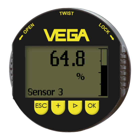
Page 10: Adjustment System
The functions of the individual keys are shown in the above illustration. Approx. 10 minutes after the last pressing of a key, an automatic reset to measured value indication is triggered. Any values not confirmed with [OK] will not be saved. Indicating and adjustment module PLICSCOM... -
Page 11: Adjustment Menu For All Signal Outputs
0 … 999 s in this menu item. Depending on the sensor type, the factory setting is 0 s or 1 s. Damping Basic adjustment/Li- In this menu item you select the linearization curve: nearization curve linear Horizontal cylindrical tank Spherical tank Indicating and adjustment module PLICSCOM... - Page 12 The available digits comprise: Letters from A … Z Numbers from 0 … 9 Special characters +, -, /, - Factory setting is "Sensor". Sensor-TAG Sensor Indicating and adjustment module PLICSCOM...
- Page 13 The fault message as well as the clear text indication are also carried out in the measured value display. Meas. reliability Sensor status Pressure: -50 … +150 % of the nominal pressure range; temperature: -50 … +150 °C. Indicating and adjustment module PLICSCOM...
- Page 14 "Stop/Start": Interrupt a recording or start a new recording "Unzoom": Reset the resolution to minutes As default setting, the recording pattern has 1 minute. With the adjustment software PACTware, this pattern can be also set to 1 hour or 1 day. Indicating and adjustment module PLICSCOM...
- Page 15 Simulation Start simulation? Service/Reset With the reset function, modified values are reset. Three subfunctions are available: Basic adjustment Reset the values modified with the indicating and adjustment module to the sensor-specific basic setting Factory setting Indicating and adjustment module PLICSCOM...
- Page 16 Deutsch English Français Espanõl Pycckuu Japanese Italiano Netherlands Japanese Chinese Special parameters are parameters which are set customer-specifically on the service level with the adjustment software PACTware. Temperature only with pressure transmitters and ultrasonic sensors. Indicating and adjustment module PLICSCOM...
- Page 17 Entering a 4-digit PIN protects the sensor data against unauthorized access and unintentional modifications. If the PIN is activated permanently, it can be deactivated temporarily (i.e. for approx. 60 min.) in any menu item. The instrument is delivered with the PIN set to 0000. Indicating and adjustment module PLICSCOM...
-
Page 18: Adjustment Menu 4 ... 20 Ma/Hart
Sensor characteristics Display now? 5.2 Adjustment menu 4 … 20 mA/HART Display/Display In the menu item "Display" you can define how the measured value should be presented on the display. Indicating and adjustment module PLICSCOM... - Page 19 0 % = 0.0 l 100 % = 100.0 l Service/Current output In the menu item "Current output" you determine the behaviour of the current output during operation and in case of failure. The following options are available: Indicating and adjustment module PLICSCOM...
- Page 20 4 … 20 mA signal. Value of the current output in case of failure, e.g. if no valid measured value is delivered. This value is not underrun during operation. This value is not exceeded during operation. Indicating and adjustment module PLICSCOM...
-
Page 21: Adjustment Menu Profibus Pa
PV lin. value The 4 … 20 mA signal of the HART sensor is switched off. The sensor consumes a constant current of 4 mA. The measuring signal is transmitted exclusively as digital HART signal. Indicating and adjustment module PLICSCOM... - Page 22 With pressure transmitters the following values are available: SV1 (Secondary Value 1): Pressure or height value before adjustment SV2 (Secondary Value 2): Percentage value after the adjustment PV (Primary Value): Linearised percentage value Additional PA value Indicating and adjustment module PLICSCOM...
- Page 23 Pressure (only with pressure transmitters) Height Mass Flow Volume Others (no unit, %, mA) In the menu item "PV-Out-Scale", the requested numerical value with decimal point is entered for 0 % and 100 % of the measured value. Out-Scale-Unit Indicating and adjustment module PLICSCOM...
-
Page 24: Adjustment Menu For All Signal Outputs
Diagnosis: Contains information on pointer, reliability, echo curve and simulation Additional settings: Contains false signal suppression, linearization curve, sensor length, reset, adjustment unit, SIL function, HART mode Info: Shows instrument type, serial number, software version, last change, sensor characteristics Indicating and adjustment module PLICSCOM... - Page 25 The optionally integrated background lighting can be adjusted via the adjustment menu. The function depends on the height of the supply voltage, see operating instructions of the respective sensor. The lighting is switched off in the delivery status. Indicating and adjustment module PLICSCOM...
- Page 26 Set the requested numerical value with [+] and [->]. Push [OK] The simulation is now running, with 4 … 20 mA/HART a current is outputted and with Profibus PA or Foundation Fieldbus a digital value. Indicating and adjustment module PLICSCOM...
- Page 27 If a linearisation curve is selected, the measuring signal is no longer compulsorily linear proportional to the level. This must be taken into consideration by the user, particularly when adjusting the switching point on the level switch. Indicating and adjustment module PLICSCOM...
- Page 28 The following data or settings for adjustment of the indicating and adjustment module are saved: All data of the menu "Setup" and "Display" In the menu "Additional settings" the items "Distance unit, temperature unit and linearization" The values of the user programmable linearization curve Indicating and adjustment module PLICSCOM...
- Page 29 In this menu item, the date of factory calibration of the sensor as well as the date of the last change of sensor parameters are displayed via the indicating and adjustment module or via the PC. Indicating and adjustment module PLICSCOM...
-
Page 30: Adjustment Menu 4 ... 20 Ma/Hart
Display/Displayed value In this menu item, you define how the measured value is displayed. There is the following relationship between the indication value in the menu "Display" and the adjustment unit in the menu "Device settings": Indicating and adjustment module PLICSCOM... - Page 31 The default setting is standard with address 0. The 4 … 20 mA signal of the HART sensor is switched off. The sensor consumes a constant current of 4 mA. The measuring signal is transmitted exclusively as digital HART signal. Indicating and adjustment module PLICSCOM...
-
Page 32: Maintenance
If a repair is necessary, please proceed as follows: You can download a return form (23 KB) from our Internet homepage www.vega.com under: "Downloads - Forms and certificates - Repair form". By doing this you help us carry out the repair quickly and without having to call back for needed information. -
Page 33: Dismounting Steps
Correct disposal avoids negative effects to persons and environment and ensures recycling of useful raw materials. Materials: see chapter "Technical data" If you have no possibility to dispose of the old instrument professionally, please contact us concerning return and disposal. Indicating and adjustment module PLICSCOM... -
Page 34: Technical Data
4 keys Protection rating unassembled IP 20 mounted into the sensor without cover IP 40 Materials Housing Inspection window Polyester foil Display light Power supply through the sensor, voltage range see sensor operating instructions manual Indicating and adjustment module PLICSCOM... -
Page 35: Dimensions
9 Supplement 9.2 Dimensions 45,1mm (1.78") 9,7mm (0.38") Fig. 3: Dimensions PLICSCOM Indicating and adjustment module PLICSCOM... - Page 36 Les lignes de produits VEGA sont globalement protégées par des droits de propriété intellectuelle. Pour plus d'informations, on pourra se référer au site http://www.vega.com VEGA lineas de productos están protegidas por los derechos en el campo de la propiedad industrial. Para mayor información revise la pagina web http://www.vega.com Линии...
- Page 37 Unit of measurement 16 HART mode - Multidrop 20, 31 - Standard 20, 31 Info 18 Instrument type 29 Instrument versions 7 Key function 10 Language 16, 25 Lighting 13, 25 Linearisation 27 Linearisation curve 11 Indicating and adjustment module PLICSCOM...
- Page 38 Index Indicating and adjustment module PLICSCOM...
- Page 39 Index Indicating and adjustment module PLICSCOM...
- Page 40 All statements concerning scope of delivery, application, practical use and operating conditions of the sensors and processing systems correspond to the information avail- able at the time of printing. © VEGA Grieshaber KG, Schiltach/Germany 2009 Subject to change without prior notice 36433-EN-091104...
Need help?
Do you have a question about the PLICSCOM and is the answer not in the manual?
Questions and answers