Vishay G4 Technical Manual
Multi channel weighing instrument
Hide thumbs
Also See for G4:
- Technical manual (194 pages) ,
- Operating instructions, quick installation (46 pages) ,
- Operating instructions manual (40 pages)

Related Manuals for Vishay G4


Summary of Contents for Vishay G4
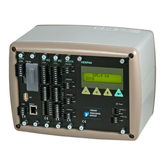
- Page 1 G4 Multi Channel Weighing Instrument Program versions 1.8.0.0, 1.9.0.0, and 1.10.0.0 Technical Manual RM type...
- Page 3 G4 Multi Channel Weighing Instrument Contents Level supervision ......5-10 Introduction Setpoint function ......5-11 General ..........1-1 Use of inputs and outputs ....5-12 Functions .......... 1-2 Filter function ......... 5-12 Maintenance ........1-4 Flow rate ........5-14 Safety information ......1-4 Communication Technical data ........
-
Page 4: Intended Use
CONNEXION USB NON AUTORISEE EN ZONE DANGEREUSE. INTENDED USE The G4 Instrument family are multi-channel measuring and control devices intended for industrial systems. Its basic function is to convert the signals from transducers to useful information. Transducer excitation is included as well as parameter controlled signal processing, indication of output levels, error supervision and operation of optional external equipment. -
Page 5: General
G4 Multi Channel Weighing Instrument 1. Introduction General The G4 Instrument is a high performance multi channel weight indicator intended for industrial systems. Its basic function is to convert the signals from strain gauge transducers to useful weight information. Transducer excitation is included as well as parameter controlled signal processing, indication of output levels, error supervision and operation of optional external equipment. -
Page 6: Functions
Communication. The G4 Instrument utilizes the serial interface, Ethernet and a fieldbus interface for communication with control computer. The serial interface consists of a RS-232 (COM1) connection and a RS-485/RS-422 (COM2) connection. COM2 can be used with 2- or 4-wire connection. - Page 7 G4 Multi Channel Weighing Instrument Instrument modes. In normal operation mode the G4 Instrument is presenting the measurement values on the front panel (VIEWPAN) alpha numerical display. Only one weight value at a time can be shown. During parameter set-up the instrument will continue normal operation. However if hardware set-up parameters have been changed the instrument will be restarted.
-
Page 8: Maintenance
Technical Manual Maintenance The G4 instrument needs no maintenance performed by the end-user. Any service or repair work must be performed by qualified personnel. Contact your supplier. Cleaning Before cleaning the G4, break the power connection to the instrument. Use a soft cloth to clean the exterior of the instrument. -
Page 9: Technical Data
G4 Multi Channel Weighing Instrument Technical data Enclosure type RM – Rail Mount enclosure Dimensions Enclosure design Aluminium housing with plastic frames Rail mount DIN 46 277/3 and DIN EN 50022 (w=35 mm, h=7.5 mm) Display, keyboard See VIEWPAN module Environmental Rated performance: -10 to +50 °C... - Page 10 Technical Manual VIEWPAN Module type Display/keypad interface with integrated power supply for the complete instrument. Input voltage 24 V ±15% including fluctuations, 40W Impulse withstand (overvoltage) category I of IEC 60364-4-443 Output voltage 24 V output 0.1 A The same voltage as input voltage Display 2 x 16 character LCD with backlight Keyboard...
- Page 11 G4 Multi Channel Weighing Instrument WF IN / WF IN2 Module type Weight/Force input module Max. # of transducers 8 (350 ohm) per channel Maximum 48 transducers per instrument Excitation voltage: 5 VDC A/D conversion: 3.9 kHz, 16 000000 units (24 bits)
- Page 12 Technical Manual HS WF2 Module type High Speed Weight/Force input module Max. # of transducers 4 (350 ohm) per channel Excitation voltage: 10 VDC A/D conversion: 20 kHz, 16 000000 units (24 bits) Input range +/- 4.5 mV/V 12.5 − 800 readings per second Update rate: No.
- Page 13 G4 Multi Channel Weighing Instrument DIO8 Module type Digital input/output module Separate I/O module 2 units can be used Digital I/O 8 inputs, 24 V ±15%, 5 mA from external power supply, isolated by operational insulation and with common return 8 outputs, 24 V ±15%, max 100 mA from external power...
- Page 14 Technical Manual Profibus-DP Module type Profibus-DP fieldbus adaptor Connector Profibus 9-pin, female D-sub (DB9F) Baudrate Auto setting 9.6 kbps – 12 Mbps Address 1 – 125, set by parameter Fieldbus data 16 bytes from fieldbus to instrument. 32 – 244 bytes from instrument to fieldbus (may be limited by the master).
-
Page 15: Parameters
G4 Multi Channel Weighing Instrument DeviceNet Module type DeviceNet fieldbus adaptor Connector 5 pin male connector. Baudrate 125, 250, 500 kbps or Auto. Set by parameter. Address 0 – 63, set by parameter Fieldbus data 16 bytes from fieldbus to instrument. -
Page 16: Ordering Information
Software (note 1) (No code specified) Standard Weighing Program Standard Weighing Program Standard Force Program Special Program (note 2) Example: G4-RM-0-4-8-0-V-W • G4 instrument (G4) • Rail mount (RM) • No field bus (0) • Slot 1 = WF IN2 (4) •... - Page 17 G4 Multi Channel Weighing Instrument Separate modules Spec.no Module type Module name 110 544 CPU unit 110 546 HS WF2 High speed dual Weight/Force input module 110 547 WF IN Single Weight/Force input module 110 548 WF IN2 Dual Weight/Force input module...
- Page 18 Technical Manual 1-14...
-
Page 19: Mechanical Installation
See chapter ‘Introduction – Technical data’ for references to RM mechanical measures. G4, RM type, should be used in a dry, clean environment or it must be mounted in a cabinet, protecting from water, dust etc. The instrument is prepared for mounting on a flat surface by DIN rail according to Technical data. -
Page 20: Electrical Installation
Technical Manual Electrical installation The field wiring of the instrument shall be suitable to the environment (e.g. chemically) in the end-user application. Field wiring installation shall comply with any national regulations, hereunder National Electrical Code (NEC) for US and/or Canadian Electrical Code for Canada. •... -
Page 21: Cpu Unit
This is a SELV/SELV-E circuit. COM1 can be used for serial communication with computer/PLC (Modbus RTU) or a printer. Point to point communication, only one G4 unit connected to the computer/PLC. Connections are made to terminals 7 - 9. Shielded cable must be used. - Page 22 Technical Manual Field Bus Slot for optional Fieldbus interface. Profibus DP-V1 and DeviceNet are available. See section Profibus-DP Fieldbus Adaptor or DeviceNet Fieldbus Adaptor later in this chapter for details. Connector for USB device(s). This port has no operational insulation and should be considered as a SELV/SELV-E circuit.
-
Page 23: Viewpan Module
The integrated power supply is used to supply the complete instrument. 24 V input Terminals 1, 2 and 3. The G4 instrument should be powered by 24 V connected according to the diagram below. To achieve functional grounding, terminal 3 should be connected to ground. - Page 24 21 and the channel 2 cable shield must be connected to terminal 14. In WF IN and WF IN2 the shield terminals are internally connected to the G4 housing, which is internally connected to earth via the power supply connector pin 3 (shield). The shield shall not be connected at any other point.
- Page 25 G4 Multi Channel Weighing Instrument 4-wire connection Transducer input, ch. 2 Exc.+ Exc+ Exc.- Sign.+ Sense+ Sign.- Transducer Exc- Sense- Sign+ Sign- Shield Junction box 6-wire connection Transducer input, ch. 1 Exc.+ Exc+ Exc.- Sign.+ Sense+ Sign.- Transducer Exc- Sense- Exc.+...
-
Page 26: Digital Inputs
Digital inputs Terminals 6 – 9 and terminal 5 (ICom) as a common connection. Four digital inputs are provided, with functions that can be set in the G4 set-up. External sourcing (24 V ) from the instrument power supply (max. 100 mA) or from a separate DC supply must be used. -
Page 27: Aout1 And Aout4
G4 Multi Channel Weighing Instrument AOUT1 and AOUT4 The voltage levels on connectors of I/O modules shall not exceed hazardous voltage levels of 30 Vrms, 42.4 Vpeak or 60 Vdc under normal conditions. In wet locations these voltage levels shall not exceed 16 Vrms, 22.6 Vpeak or 35 Vdc. -
Page 28: Dio8
Digital inputs Terminals 11 – 18 and terminal 19 (ICom) as a common connection. Eight digital inputs are provided, with functions that can be set in the G4 set-up. External sourcing (24 V ) from the instrument power supply (max. 100 mA) or from a separate DC supply must be used. -
Page 29: Profibus-Dp Fieldbus Adaptor
G4 Multi Channel Weighing Instrument Profibus-DP Fieldbus Adaptor Profibus module front view (1) Operation mode LED. (2) Status LED. (3) Profibus connector. PROFIBUS DP-V1 Operation mode LED State Indication Not online / No power Green On-line, data exchange Flashing Green... - Page 30 For reliable fieldbus function, line termination must be arranged in both ends of the transmission line. For a G4 instrument, at the end of the cable, a connector with line termination should be used. For all other G4 Instruments connection without line termination should be used.
-
Page 31: Devicenet Fieldbus Adaptor
G4 Multi Channel Weighing Instrument DeviceNet Fieldbus Adaptor DeviceNet module front view (1) Network Status LED. (2) Module Status LED. (3) DeviceNet connector. DeviceNet (Pin 1) Network Status LED State Indication Not online / No power Green On-line, one or more connections are established... - Page 32 For reliable fieldbus function, line termination must be arranged in both ends of the transmission line. For a G4 instrument placed at the end of the line, terminate line by placing a 121-ohm resistor between CAN L (pin 2) and CAN H (pin 4).
- Page 33 Warning: Changes done during editing of set-up parameters will affect the behaviour of the instrument immediately. The user must take all necessary precautions to prevent any undesired effects in the process monitored or controlled by the G4 instrument or a connected control system.
- Page 34 The output function e.g. if the output shall be active above or below the set level is configured here. The fourth parameter for each level is the hystereses setting. Setpoints: The G4 instrument contains 16 setpoints that are individually configurable regarding which scale it shall be connected to and which signal it shall monitor.
-
Page 35: Operators Interface
G4 Multi Channel Weighing Instrument Batching Parameters: This menu is only shown if the batching option is enabled. It contains batching settings for all scales. See the separate ‘Scale Batching Program Option’ ‘Technical Manual Supplement’ for details. Program Options: This menu contains the options that can be used. Program options are enabled using a purchased option code. -
Page 36: Menu Structure
Technical Manual From the weight display, showing the main menu is done by pressing ‘+’ and ‘↑’ keys simultaneously for 1 second. The ViewPan ‘+’ and ‘−’ keys are used to scroll the available menu items and the ‘↵’ key is used to enter the selected sub menu. Pressing the ‘↑’ key when in the main menu will make the instrument show the weight display. - Page 37 G4 Multi Channel Weighing Instrument Parameter Set-up menu To enter a Parameter Set-up sub menu the desired one is selected by scrolling with ‘+’ or ‘−’ Main Menu keys until it’s shown. Then the sub menu is Param. Set-up entered by pressing ‘↵’. Returning to ‘Main Menu’...
- Page 38 Technical Manual Parameter editing procedure Parameter set-up This example shows the ‘General’ parameter General menu but editing is done similar throughout the menu system. The desired menu is selected by scrolling Language Edit with ‘+’ or ‘−’ keys until it is shown. Then the English parameter sub menu is entered by pressing ‘↵’.
- Page 39 G4 Multi Channel Weighing Instrument...
- Page 40 Technical Manual Menu structure Main Menu *Levels *Setpoints *Preset Tare Note that Batching and Flow rate are optional. The respective parameters and *Accum. Weights menus are only shown when the program option is enabled. *Batched Weights *Clock Set-up *Param. Set-up *menu *System Info.
- Page 41 G4 Multi Channel Weighing Instrument (Previous page) Param. Set-up System Info. Maintenance Network Config *General *Diagnostics Information on *IP Config. *Hardware Config. *File Handling serial numbers, *Server Config. *Calibration *Create Backup program *Communication *Restore Backup versions, network *Level Superv. *Set Default...
- Page 42 Technical Manual (Previous page) Batching Param. Program Options *S1 Batch.Param. 01:Flow rate *S2 Batch.Param. 02:Scale batch. *S3 Batch.Param. 03:EtherNet/IP *S4 Batch.Param. *S5 Batch.Param. *S6 Batch.Param. *S7 Batch.Param. *S8 Batch.Param. S1 Batch.Param. S1:Disp no of B. S1:Displ. B-Size S1:Batch Print. S1:File Log S1:Batch E.Mode *S1A1:** *S1A2:**...
- Page 43 G4 Multi Channel Weighing Instrument Parameters On the following pages a survey of all parameters is presented. The parameters are divided in groups following the menu they belong to. For choice parameters the available choices are given. For numerical parameters, a value range is given.
- Page 44 Technical Manual Range/Alternatives Explanation and <default value> result of alternatives. Display Contrast Defines the text contrast for the alphanumerical display. Low values giving lower contrast. High values giving sharper characters but reduced readability at slanted display. <5> Date Format YYYY-MM-DD Defines the date format.
- Page 45 G4 Multi Channel Weighing Instrument Range/Alternatives Explanation and <default value> result of alternatives. Operator Lock Off: Operator lock is not activated. On: Operator lock is activated, preventing unauthorised access <Off> to the instrument. See chapter 'Operation – Security locks'. Operator Code Range: Defines the valid code for Operator lock.
- Page 46 Technical Manual Range/Alternatives Explanation and <default value> result of alternatives. Menu ‘Hardware Config.’ Fieldbus Not In Use This parameter defines what type of fieldbus that will be used in Profibus the CPU. DeviceNet Not In Use: The fieldbus is not used regardless of any installed <Not In Use>...
- Page 47 G4 Multi Channel Weighing Instrument Range/Alternatives Explanation and <default value> result of alternatives. Slot 2 Module < No module > This parameter defines what type of I/O- module is installed in slot 2. See ‘Slot 1 Module’ for details on parameter values.
- Page 48 Technical Manual Range/Alternatives Explanation and <default value> result of alternatives. Menu ‘Scale 1’ The Calibration menu contains up to 8 sub menus, one for each installed/used scale. The parameters are the same for all 8 scale menus. Here only scale 1 parameters are shown.
- Page 49 G4 Multi Channel Weighing Instrument Range/Alternatives Explanation and <default value> result of alternatives. 1:Capacity Range: Nominal range of scale. 0.5 to 999999 Capacity / Resolution = Number of divisions. Unit: Measurem. unit <500> 1:HSWF Update R. 12.5 Hz Defines the update rate for the measuring channel belonging to 25 Hz scale 1 if the weight conversion module is of HS WF2 type.
- Page 50 Technical Manual Range/Alternatives Explanation and <default value> result of alternatives. 1:No Motion Dely Range: Delay in seconds from detection of stable weight 0 to 10.0 until the Motion status goes off. Unit: s <1.0> 1:Motion Check Off: Only zero adjustment is inhibited during motion. On: Inhibits zero adjustment, taring, and printing during motion.
- Page 51 G4 Multi Channel Weighing Instrument Range/Alternatives Explanation and <default value> result of alternatives. 1:Zero Tracking With this parameter automatic zero-tracking can be selected, or a combination of automatic zero-tracking and automatic zero On+AutoZero setting. <Off> Off: No zero tracking. On: Zero tracking active.
-
Page 52: Program Options
Technical Manual Range/Alternatives Explanation and <default value> result of alternatives. 1:Flow Calc. Used to turn on and off the flow rate calculations. On: Flow rate calculations are performed. <Off> Off: Flow rate calculations are not performed. Note: the flow rate calculation is optional and this parameter is only shown if the Flow rate program option code is entered. - Page 53 G4 Multi Channel Weighing Instrument Range/Alternatives Explanation and <default value> result of alternatives. 1:Auto Deriv. T The derivation time can be entered manually or calculated automatically by the instrument. <On> Off: Manual entering of derivation time. On: Automatic calculation of derivation time.
- Page 54 Technical Manual Range/Alternatives Explanation and <default value> result of alternatives. Menu ‘Scale 1 Calib’ The Scale 1 Calibration menu is found after the last parameter in menu Scale. Here only scale 1 menu is shown. Note that the scale number is shown as a prefix to the parameter name, here ‘1:’...
- Page 55 G4 Multi Channel Weighing Instrument Range/Alternatives Explanation and <default value> result of alternatives. 1:Rated Output 1 Range: Defines the rated output signal for transducer 1. 0 to 9.99999 The value is specified in the transducer data sheet Unit: mV/V for transducer 1.
- Page 56 Technical Manual Range/Alternatives Explanation and <default value> result of alternatives. Deadweight calibration related parameters Used when the scale is calibrated with weights. The instrument automatically reads the corresponding transducer signals. 1:No of Cal. P Range: Number of calibration points. 2 to 6 <2>...
- Page 57 G4 Multi Channel Weighing Instrument Range/Alternatives Explanation and <default value> result of alternatives. 1:T.Signal P1 Range: +/–9.99999 In this parameter, the transducer signal in Unit: mV/V the lowest calibration point is displayed, <0.00000> but the value cannot be edited. 1:T.Signal P2 Range: +/–9.99999...
- Page 58 Technical Manual Range/Alternatives Explanation and <default value> result of alternatives. Table calibration related parameters Used when the scale is calibrated with recorded values from a previous calibration, normally a deadweight calibration. 1:No of Cal. P Range: Number of calibration points. 2 to 6 <2>...
- Page 59 G4 Multi Channel Weighing Instrument Range/Alternatives Explanation and <default value> result of alternatives. 1:T.Signal P1 Range: +/–9.99999 In this parameter, enter the recorded value for the Unit: mV/V transducer signal in the first calibration point. <0.00000> 1:T.Signal P2 Range: +/–9.99999...
- Page 60 Technical Manual Range/Alternatives Explanation and <default value> result of alternatives. Menu ‘Serial Com.’ Modbus Address Range: 1 to 247 Defines the instrument Modbus address. <1> COM1:Mode Not in use Defines use of serial port Com 1. Modbus Slave Not in use: The port is not used. Printer Modbus Slave: The port is used for control unit communication.
- Page 61 G4 Multi Channel Weighing Instrument Range/Alternatives Explanation and <default value> result of alternatives. COM1:Float Form. Modicon Float Sets how the Modbus slave should handle floating point Float values. < Modicon Float > Modicon Float: Modicon floating point format. Float: IEEE 32 bit floating point format See chapter ‘Communication’...
- Page 62 Technical Manual Range/Alternatives Explanation and <default value> result of alternatives. COM1:Print Pos.3 Not in use Specifies the information that should be printed in printer Display Weight position 3 (lower left field). This parameter controls weight Preset Tare printing but not batching printouts. Date/Time Not in use: Printer position 3 is left empty.
- Page 63 G4 Multi Channel Weighing Instrument Range/Alternatives Explanation and <default value> result of alternatives. COM2:Mode Not in use Defines the use for serial port Com 2. Modbus Slave Not in use: The serial port is not used. Printer Modbus Slave: The serial port is used for communication with a <Not in use>...
- Page 64 Technical Manual Range/Alternatives Explanation and <default value> result of alternatives. COM2:Print Pos.1 Not in use Specifies the information that should be printed in printer Display Weight position 1 (upper left field). This parameter controls weight Preset Tare printing but not batching printouts. Date/Time Not in use: Printer position 1 is left empty.
- Page 65 G4 Multi Channel Weighing Instrument Range/Alternatives Explanation and <default value> result of alternatives. COM2:Print Pos.4 Not in use Specifies the information that should be printed in printer Display Weight position 4 (lower right field). This parameter controls weight Preset Tare printing but not batching printouts.
- Page 66 Technical Manual Range/Alternatives Explanation and <default value> result of alternatives. Menu ‘Modbus TCP Slave’ Modbus TCP Slave Enables/disables the Modbus TCP Slave. On: Modbus TCP Slave enabled. <Off> Off: Modbus TCP Slave disabled. Float Format Modicon Float Sets how the Modbus TCP Slave should handled floating point Float values.
- Page 67 G4 Multi Channel Weighing Instrument Range/Alternatives Explanation and <default value> result of alternatives. Menu ‘EtherNet/IP’ Note: The EtherNet/IP menu is only shown if the EtherNet/IP option is enabled, see menu ‘Program Options’. See chapter ‘Communication – EtherNet/IP interface’ for more details on EtherNet/IP configuration and usage.
- Page 68 Technical Manual Range/Alternatives Explanation and <default value> result of alternatives. Block 1 Format Floating Point Sets the Data Block 1 format. Integer Floating Point: The Data Block format is floating point. < Floating point > Integer: The Data Block format is integer. Note: This parameter is only shown if parameter ‘No Of Data Block‘...
- Page 69 G4 Multi Channel Weighing Instrument Range/Alternatives Explanation and <default value> result of alternatives. Menu ‘Fieldbus’ Note: The Fieldbus menu is not shown if parameter ‘Fieldbus‘ (in Hardware Config menu) is set to ‘Not In Use’. See chapter ‘Communication − Fieldbus interface’ for more details on fieldbus configuration and usage.
- Page 70 Technical Manual Range/Alternatives Explanation and <default value> result of alternatives. Block 1 Type Not In Use Sets the data source for Data Block 1. Gross Weight Not In Use: The memory area corresponding to this data block Net Weight is not updated. Disp.
- Page 71 G4 Multi Channel Weighing Instrument Range/Alternatives Explanation and <default value> result of alternatives. Block 1 Scale Selects the source scale for Data Block 1. 1: The Data Block uses data from scale no 1. 2: The Data Block uses data from scale no 2.
- Page 72 Technical Manual Range/Alternatives Explanation and <default value> result of alternatives. Menus ‘Level 1’ – ‘Level 32’ NOTE: There are 32 levels each with the following four parameters described below. Level 1 Source ( - Level 32 Source) Not in use Defines the signal to be supervised by the level.
- Page 73 G4 Multi Channel Weighing Instrument Range/Alternatives Explanation and <default value> result of alternatives. Menu ‘Setpoints’ NOTE: There are 16 setpoints each with the following two parameters described below. Setp. 1 Source ( - Setp. 16 Source) Not in use Defines the signal to be supervised by the setpoint.
- Page 74 Technical Manual Range/Alternatives Explanation and <default value> result of alternatives. Menu ‘Inputs Slot 1’ - ‘Inputs Slot 3’ NOTE: There are three possible sub menus, one for each slot. In each slot sub menu there are up to 8 possible inputs named 11 to 18 for slot 1, 21 to 28 for slot 2 and so on.
- Page 75 G4 Multi Channel Weighing Instrument Range/Alternatives Explanation and <default value> result of alternatives. Menu ‘Outputs Slot 1’ - ‘Outputs Slot 3’ NOTE: There are three possible sub menus, one for each slot. In each slot sub menu there are up to 8 possible outputs named 11 to 18 for slot 1, 21 to 28 for slot 2 and so on.
- Page 76 Technical Manual Range/Alternatives Explanation and <default value> result of alternatives. Output 11 Level (- Output 18 Level) 1: Level number 1 uses the output. 2: Level number 2 uses the output. 3: Level number 3 uses the output. …. …. 30: Level number 30 uses the output.
- Page 77 G4 Multi Channel Weighing Instrument Range/Alternatives Explanation and <default value> result of alternatives. Menu ‘Analog Outputs’ NOTE: There are 4 possible analog outputs each with the 8 parameters described below. If the selected analog output module is AOUT4 there will be parameters for four analog outputs displayed, if the AOUT1 is selected only the parameters for the first analog output (shown below) will be shown.
- Page 78 Technical Manual Range/Alternatives Explanation and <default value> result of alternatives. AOUT1 Range Low (- AOUT4 Range Low) Range: Defines the weight/flow rate value that should +/–999999 give the lowest output (0 V / 0 mA / 4 mA) at this Unit: Analog output.
- Page 79 G4 Multi Channel Weighing Instrument Range/Alternatives Explanation and <default value> result of alternatives. Menu ‘Batching Parameters’ Batching parameters will only be shown if the Scale Batching program option is enabled. See the ‘Scale Batching Program Option’ ‘Technical Manual Supplement’ for a description of the Batching functionality and parameters.
- Page 80 Technical Manual Program options A program option is a program functionality that must be purchased separately. It is not available until a valid option code is entered. An option code can be purchased at the same time as the instrument or separately at a later occasion. The program option code is directly related to the individual S/N of the CPU module.
-
Page 81: General
G4 Multi Channel Weighing Instrument 4. Calibration General When measuring with G4 Instrument, the transducer output signal, corresponding to the transducer load, is converted to a weight value. The conversion is controlled by several parameters with values defined during calibration of the instrument. -
Page 82: Common Parameters
Technical Manual If the weight indicator must be replaced, a table calibration of the replacement unit can be performed, with recorded values from an earlier calibration. To get the best accuracy, a deadweight calibration with known weights to at least 2/3 of the measuring capacity, should be performed. - Page 83 G4 Multi Channel Weighing Instrument Number of scale divisions The number of scale divisions (div.) for a scale = ‘Capacity’ / ‘Resolution’. To get correct and stable weight display, parameter ‘Resolution’ should be set so that the number of scale divisions with the selected ‘Capacity’ is less than 6 000 (10 000).
-
Page 84: Data Sheet Calibration
0.1 % can be obtained. The accuracy of the G4 Instrument itself is 0.005 % (1-2 years calibration period). It is essential that no external forces influence the scale installation. If fixed support points are included in the scale, the load must be evenly distributed on transducers and fixed supports. -
Page 85: Table Calibration
G4 Multi Channel Weighing Instrument Zero Offset For an installed scale this parameter shows the zero offset after zeroing, a value that should not be edited. For a scale that is not installed it is possible to enter the known weight of fixed equipment on the scale. - Page 86 Technical Manual selected, and parameters for load value and transducer signal will be displayed only for the selected number of points. It is possible to change the number of points during the calibration. Value Cal. P1, This parameter defines the load for the lowest calibration point. Normally the scale should be unloaded and the parameter value set to 0 (zero).
-
Page 87: General
G4 Multi Channel Weighing Instrument 5. Operation General G4 instrument with strain gauge transducers is designed mainly for weighing and batching purposes. The measurement values are displayed at the front panel, and can also be transmitted to a master computer/PLC. -
Page 88: Weight Display
Technical Manual Weight display In the weight display it is possible to display weight information from one scale at a time. The ViewPan ‘+’ and ‘−’ keys are used to toggle between the available scales. If a program option is enabled in demo mode there will be an indication on the display, see picture. -
Page 89: Security Locks
G4 Multi Channel Weighing Instrument Security locks In the G4 instrument two security locks are included to prevent unauthorised access to the instrument via the panel keys. The locks can be activated by parameters in menu ‘Main menu/Param. set-up/General’. The following requires a login password if the corresponding lock is on. -
Page 90: Taring
Technical Manual Taring Taring means storing of a tare value and that the instrument switches over to display of net weight. The net weight being the gross weight minus the tare value. In the instrument two tare values can be stored, Auto tare and Preset tare. ‘Auto’... -
Page 91: Gross/Net Operation
G4 Multi Channel Weighing Instrument Gross/Net operation At normal operation the instrument presents a numerical weight value at the display, either gross weight or net weight. When net weight is displayed the text ‘N’ is displayed on the lower line. -
Page 92: Motion
Technical Manual Zero-tracking/Automatic zero setting In the instrument the functions zero-tracking and automatic zero setting can be enabled. Zero-tracking gives a continuous zero setting by slow changes in zero weight. The automatic zero setting performs zeroing of small negative gross weights. For both functions the following requirements should be met: •... -
Page 93: Weight Printing
A printer can be used to print the displayed weight or the displayed flow rate. It can also be used to print batching report if the Scale Batching Program Option is enabled. The printer must be connected to one of the G4 Instrument serial communication ports and the communication parameters must be correctly set. -
Page 94: Batch Report Printing
Technical Manual Weight accumulation The print function and communication print command is also used to accumulate the displayed weight. See the description of accumulated weights below under Main menu. Accumulation is done even if no printer is set-up or connected. Batch report printing See the separate ‘Scale Batching Program Option’... - Page 95 Clock Set-up: Used to set the instrument clock and date. Time and Date formats are set-up with parameters trough ‘Param. Set-up’ menu. Param. Set-up: Access to the G4 instrument parameter set-up menu system. See chapter ‘Set-up’ for more details on setup.
-
Page 96: Level Supervision
Technical Manual Level supervision The G4 instrument contains 32 supervision Levels that can be used to supervise defined signals in the instrument. Digital outputs can be connected as outputs for the Levels. For each Level, supervised scale, hystereses and operation mode for the digital output is controlled by set-up parameters. -
Page 97: Setpoint Function
G4 Multi Channel Weighing Instrument via communication. The level status includes the influence from hystereses, but it does not show the status of any digital outputs, connected to the Levels. Setpoint function General The 16 Setpoints can be used for fast, accurate and reliable supervision of weight values. -
Page 98: Use Of Inputs And Outputs
Analog outputs To produce analog outputs from the G4 instrument, a one channel AOUT1 or a four channel AOUT4 module is used. The analog output signal will represent a selected signal in the instrument in form of an analog current or voltage signal. - Page 99 G4 Multi Channel Weighing Instrument WF IN / WF IN2 module filter bandwidth Update - 3 dB frequency - 90 dB frequency rate Filtered Unfiltered Filtered Unfiltered 300 Hz 14 Hz 22 Hz 75 Hz 150 Hz 150 Hz 7.6 Hz...
-
Page 100: Flow Rate
Flow rate General The G4 instrument includes a program option for flow measurement. The option can be activated by an individual code for each instrument. The code can be ordered from your supplier. The program option code should be entered in the ‘Program Options’... - Page 101 G4 Multi Channel Weighing Instrument Setting of flow rate unit Parameter ‘Flow Rate Unit’ defines the engineering unit that should be used for the flow rate value and for related set-up parameters. If the flow rate unit exceeds 4 characters then it will be represented as ”/s”, ”/min”,”/h”, ”*/mi”...
- Page 102 Technical Manual Flow rate update time The flow rate value is updated as shown in the table below. At start-up the accuracy of the flow rate will not gain full precision until after a full derivation time period. Number of weight conversions per Flow rate value update interval derivation time period <= 100...
- Page 103 G4 Multi Channel Weighing Instrument Hints and examples First of all it is important to have a good weighing application where you use the load cells in a good way to get high resolution and accuracy. It is possible to use long filter time in the instrument to get a higher resolution and accuracy.
- Page 104 Technical Manual 5-18...
-
Page 105: General
Modbus RTU Slave General All the G4 units connected to the network can listen to what is transmitted in the network, but only one unit at a time may transmit. A time-sharing principle is needed to allow communication in both directions (half duplex). -
Page 106: Modbus Tcp Slave
The instrument will as default be given the address 1. If more than one instrument is used in a network, each G4 instrument must be given a unique address in parameter ‘Modbus address’ (in ‘Parameter set-up’, menu ‘Communication’, sub menu ‘Serial Com.’). -
Page 107: External I/O
WAGO I/O system communicate over Ethernet using the Modbus TCP protocol. The G4 CPU module can handle both 10 and 100 Mbit/s networks. It is possible to use switches, hubs etc in the network. Note that the communication performance will be affected by the network speed, network load, scale update rate etc. -
Page 108: Ethernet/Ip
Information about EtherNet/IP and the ODVA can be obtained from the ODVA web site www.odva.org The G4 Instrument is classified as a CIP Adapter Class device of Generic Device Type. The EtherNet/IP interface of the instrument supports three types of transport: 1. -
Page 109: Connection Manager
G4 Multi Channel Weighing Instrument Identity Object The Identity Object class code is 0x0.1. Supported Class Attributes: Attribute name Value Revision Max Instance Number of Instances Supported Instance Attributes: Attribute name Value Vendor ID 1179 Device Type Generic Device Type... - Page 110 Technical Manual TCP/IP Interface Object The CP/IP Interface Object class code is 0xF5. Supported Class Attributes: Attribute name Value Revision Max Instance Number of Instances Supported Instance Attributes: Attribute name Remarks Status See note 1 Configuration Capability See note 2 Configuration Control No configuration control support Physical Link Object...
- Page 111 G4 Multi Channel Weighing Instrument Ethernet Link Object. The Ethernet Link Object class code is 0xF6. Supported Class Attributes: Attribute name Value Revision Max Instance Number of Instances Supported Instance Attributes: Attribute name Remarks Interface Speed Value 0 (Speed indeterminate)
- Page 112 Assembly Object The Assembly Object class code is 0x04. The assembly object is used to receive and transmit data to and from the G4 instrument. This data is measurements, status, input and output status etc. Any communication regarding this type of instrument data is done through the Assembly object.
-
Page 113: Ftp Server
100 if no control of the instrument is desired. Ftp Server The G4 instrument contains an ftp server that can be used to transfer files between the instrument and an external computer using an ftp client. To connect to the instrument the ftp client must login to the instrument with the user ID ‘G4User’... - Page 114 Technical Manual See the master's own Modbus driver documentation for how the commands should be activated in the master's application programme. Most manufacturers of PLC systems and HMI and SCADA software can provide Modbus drivers. Various Modbus drivers for development of Windows programs are also available on the market.
- Page 115 G4 Multi Channel Weighing Instrument General registers The instrument has a number of Modicon 'Holding Registers' (registers 4XXXX...). The Modbus function 03 'Read Holding Registers' should be used to read these registers and the Modbus function 05 'Preset Single Register' or 16 'Preset Multiple Registers' should be used to write to the registers.
- Page 116 Technical Manual Data type: Data type: float Explanation Integer (2 reg./value) 40062 (1 reg) 44062 Scale 3: Error code 40063 (1 reg) 44064 Scale 3: Status 40064 (3 reg) 44066 Scale 3: Gross weight 40067 (3 reg) 44068 Scale 3: Net weight 40070 (3 reg) 44070 Scale 3: Flow rate...
- Page 117 G4 Multi Channel Weighing Instrument Data type: Data type: float Explanation Integer (2 reg./value) 40132 (1 reg) 44122 Scale 8: Error code 40133 (1 reg) 44124 Scale 8: Status 40134 (3 reg) 44126 Scale 8: Gross weight 40137 (3 reg)
- Page 118 Technical Manual Data type: Data type: float Explanation Integer (2 reg./value) 42010 (3 reg) 46010 Scale 1: Preset tare value 42013 (3 reg) 46012 Scale 2: Preset tare value 42016 (3 reg) 46014 Scale 3: Preset tare value 42019 (3 reg) 46016 Scale 4: Preset tare value 42022 (3 reg)
- Page 119 G4 Multi Channel Weighing Instrument Data type: Data type: float Explanation Integer (2 reg./value) 42106 (3 reg) 46074 Level 25 value 42109 (3 reg) 46076 Level 26 value 42112 (3 reg) 46078 Level 27 value 42115 (3 reg) 46080 Level 28 value...
- Page 120 Technical Manual Accumulated weight registers Accumulated weights are updated when a print command is issued. The accumulated values can also be read in the ‘Accumulated Weights’ menu in the ‘Main menu’. In this menu it is also possible to zero or set the values. There is also a set of registers that contain the Batched Weights, which are accumulated weights automatically calculated during batching.
-
Page 121: Instrument Type
G4 Multi Channel Weighing Instrument Instrument type This register holds the type of the instrument. For G4 Multi Channel Weighing Instrument this value is 4001. Standard program major and minor version This registers holds the major and minor version for a standard program. - Page 122 Technical Manual Instrument state This register contains the state of the G4 instrument unit. Code Description ‘Starting up’ state. The instrument is starting up after a reset or power on. ‘Wait for start’ state. The instrument is waiting for a start command to go in process.
- Page 123 G4 Multi Channel Weighing Instrument Instrument status This register holds the overall status for the instrument Bits set to 1 in this register have the following meaning: Bit no Function Comment Remote operation ‘1’ = On ‘0’ = Off Program reset The bit is set each time the program starts, and it indicates that volatile data is lost.
- Page 124 Technical Manual Scale X: Status Status for a scale. Bits set to 1 in this register have the following meaning: Bit no Function Comment Net weight > INT size The net weight in ‘scaled integer’ format does not fit in one register. (See description of data representation.) Gross weight >...
- Page 125 G4 Multi Channel Weighing Instrument Scale X: Gross weight This register holds the gross weight for a scale. The weight should not be read alone because the status and error codes are stored in other registers. The weight is only valid when the register ‘Scale X:Error code’...
- Page 126 Technical Manual Digital input 31 activated. Digital input 41 activated. Digital input 32 activated. Digital input 42 activated. Digital input 33 activated. Digital input 43 activated. Digital input 34 activated. Digital input 44 activated. Digital input 35 activated. Digital input 45 activated. Digital input 36 activated.
- Page 127 G4 Multi Channel Weighing Instrument Status of outputs 11-18, 21-28 Bits set to 1 in this register have the following meaning: Bit no Function Bit no Function Digital output 11 activated. Digital output 21 activated. Digital output 12 activated. Digital output 22 activated.
- Page 128 Technical Manual Status of outputs 51-58, 61-68 Bits set to 1 in this register have the following meaning: Bit no Function Bit no Function Digital output 51 activated. Digital output 61 activated. Digital output 52 activated. Digital output 62 activated. Digital output 53 activated.
- Page 129 G4 Multi Channel Weighing Instrument Level status 1-16 Bits set to 1 in this register have the following meaning: Bit no Function Comment Above level 1 The weight is above Level 1. Above level 2 The weight is above Level 2.
- Page 130 Technical Manual Level status 17-32 Bits set to 1 in this register have the following meaning: Bit no Function Comment Above level 17 The weight is above Level 17. Above level 18 The weight is above Level 18. Above level 19 The weight is above Level 19.
- Page 131 G4 Multi Channel Weighing Instrument Setpoint status 1-8 Bits set to 1 in this register have the following meaning: Bit no Function Comment Setpoint 1 activated See description for setpoint function. Setpoint 1 cycle done See description for setpoint function.
- Page 132 Technical Manual Setpoint status 9-16 Bits set to 1 in this register have the following meaning: Bit no Function Comment Setpoint 9 activated See description for setpoint function. Setpoint 9 cycle done See description for setpoint function. Setpoint 10 activated See description for setpoint function.
- Page 133 G4 Multi Channel Weighing Instrument Command register As this register is read, the answer will always contain only zero's. There are a number of actions that can be activated in the instrument. The value of this register (when different from zero) will activate one of these actions, as described in below.
- Page 134 Technical Manual Cmd Action activated in Description instrument Scale 3: Select gross mode Scale 3: Select net mode Scale 3: Weight display Show weight on the display. Scale 3: Flow rate display Show flow rate on the display. Scale 3: Print command Initiate a weight printout Scale 4: Auto tare Scale 4: Set to zero...
- Page 135 G4 Multi Channel Weighing Instrument Cmd Action activated in Description instrument Scale 7: Weight display Show weight on the display. Scale 7: Flow rate display Show flow rate on the display. Scale 7: Print command Initiate a weight printout Scale 8: Auto tare Scale 8: Set to zero Used to set the gross weight to zero.
- Page 136 Technical Manual Cmd Action activated in Description instrument Activate setpoint 12 See description of setpoint function. Deactivate setpoint 12 See description of setpoint function. Activate setpoint 13 See description of setpoint function. Deactivate setpoint 13 See description of setpoint function. Activate setpoint 14 See description of setpoint function.
- Page 137 G4 Multi Channel Weighing Instrument Scale X: Preset tare value This registers is used to read and write a new preset tare for a scale. Level X value These registers are used to read and write levels that are supervised by the instrument.
- Page 138 Technical Manual Data representation Data sent to and from the instrument uses 16 bit holding registers (40XXX) and can use different formats for flexibility. Integer Unsigned integer (1 modbus register) Values stored in one modbus register as an unsigned integer (16 bit number without decimals).
- Page 139 G4 Multi Channel Weighing Instrument Float values The type of float values used in the communication is selected in the set-up for the different communication interfaces. Values stored as standard IEEE 32 bit float values. Each value has two registers assigned to it.
- Page 140 Technical Manual Exception responses When the master sends a query to a slave it expects a normal response (as described earlier). One of the following three events occurs after a query from the master. 1. Normal response. The slave has received the query without communication error and can handle the query normally.
- Page 141 G4 Multi Channel Weighing Instrument Supported Modbus functions Function Description Reads the state of discrete outputs (0X references, coils). Only implemented because some 'masters' use this function to initiate Read Coil Status communication. Coil range: 1 – 16 (Max number of points to read: 16).
-
Page 142: Fieldbus Interface
Technical Manual Fieldbus interface The optional fieldbus interface is based on a network communication module from HMS Industrial Networks. Available fieldbusses are Profibus and DeviceNet. With setup parameters the fieldbus interface is configured for the specific needs of an installation. It is possible to setup address, baud rate (if applicable to the actual fieldbus type) and mapping of the memory area in the fieldbus module that is available to the network. -
Page 143: Fieldbus And Ethernet/Ip Data Def
G4 Multi Channel Weighing Instrument Fieldbus and EtherNet/IP Data Definitions Data from the network (Outputs in the master) General This 16 bytes block is mandatory, i.e. it is always mapped to the network in the instrument. Byte Contents Command Number of registers to write... - Page 144 Technical Manual Byte 1: Used to define the number of registers to write. Bytes 2 and 3: Define from which register number to read or write. Bytes 4 to 15: Contains the data when writing to the instrument. Data to the network (Inputs in the master) General Data to the network are divided into two categories, one is the mandatory “base block”...
- Page 145 G4 Multi Channel Weighing Instrument The first 32 bytes of data from the instrument to the network are mandatory. Bytes 0 and 1: Contains the actual instrument error information (the value 0 means no error). See chapter ‘Communication – Modbus protocol – Instrument error’.
- Page 146 Technical Manual Configurable data blocks Data Blocks is used to transfer data from Byte Contents the instrument to the master. Up to 12 data Start of data block 1 blocks can be used. Each block consist of 16 bytes. The data blocks have fixed Start of data block 2 positions in memory, see list to the left.
- Page 147 G4 Multi Channel Weighing Instrument Weight data block (Floating-point format) Byte Contents Offset + 0 Scale x: Error code Offset + 1 Scale x: Error code Offset + 2 Scale x: Error code Offset + 3 Scale x: Error code...
- Page 148 Technical Manual Weight data block (Integer format) Byte Content Offset + 0 Scale x: Error code Offset + 1 Scale x: Error code Offset + 2 Scale x: Status Offset + 3 Scale x: Status Offset + 4 Scale x: Data, int Offset + 5 Scale x: Data, int Offset + 6...
- Page 149 G4 Multi Channel Weighing Instrument Level status (Floating-point format) Byte Content Offset + 0 Level status 1 – 16 Offset + 1 Level status 1 – 16 Offset + 2 Level status 1 – 16 Offset + 3 Level status 1 – 16 Offset + 4 Level status 17 –...
- Page 150 Technical Manual Input Status (Floating-point format) Byte Content Offset + 0 Status of inputs 11 – 18, 21 – 28 Offset + 1 Status of inputs 11 – 18, 21 – 28 Offset + 2 Status of inputs 11 – 18, 21 – 28 Offset + 3 Status of inputs 11 –...
- Page 151 G4 Multi Channel Weighing Instrument Inp./Outp Stat (Integer format) Byte Content Offset + 0 Status of inputs 11 – 18, 21 – 28 Offset + 1 Status of inputs 11 – 18, 21 – 28 Offset + 2 Status of inputs 31 – 38, 41 – 48 Offset + 3 Status of inputs 31 –...
- Page 152 Technical Manual AOUT1-4 Value (Floating-point format) Byte Content Offset + 0 Analog output value 1 Offset + 1 Analog output value 1 Offset + 2 Analog output value 1 Offset + 3 Analog output value 1 Offset + 4 Analog output value 2 Offset + 5 Analog output value 2 Offset + 6...
- Page 153 G4 Multi Channel Weighing Instrument AOUT3-4 Value (Integer format) Byte Content Offset + 0 Analog output value 3, int Offset + 1 Analog output value 3, int Offset + 2 Analog output value 3, int Offset + 3 Analog output value 3, int...
- Page 154 Technical Manual Examples Example 1: Setting ‘Level 1 Value’ to 123.5 (Writing to float value register). 1. Make sure that the previous command was not 251. Set command byte (00) to 0 if previous command was 251. 2. Set number of registers (2) to write in byte 01. 3.
- Page 155 G4 Multi Channel Weighing Instrument Example 3: Set read window to read from Scale 4 floating point data (registers 44074 to 44085). Note that the number of registers read is always 12. 1. Make sure that the previous command was not 250.
-
Page 156: Weight Printing
The print function is designed to work best with a 40-character printer. Displayed weight or flow rate can be printed. The printing functionality in the G4 Instrument uses the multilingual character set known as Microsoft OEM code page 437 (US), MS-DOS code page 437, IBM character set No. - Page 157 G4 Multi Channel Weighing Instrument Print examples Print Pos. 1 = Date/Time Print Pos. 2 = Scale Name Print Pos. 3 = Not in use Print Pos. 4 = Display Weight Linefeeds = 2 Scale 1 Name = Ice cream...
- Page 158 Technical Manual 6-54...
-
Page 159: General
Configuration’ menu is the ‘Server Config’ menu found where the Web Server can be enabled (default) or disabled. Also the password can be set here. The remote access interface of the G4 instrument is intended to facilitate the set-up and maintenance work with the instrument. During e.g. commissioning it will make it possible to have the PC close to the equipment when the instrument is placed away from the equipment. -
Page 160: Using The Remote Access
Technical Manual Using the Remote Access To navigate in the menu system a mouse, touch pad, pointing stick etc. must be used. The keyboard cannot be used for navigation. Hovering with the mouse pointer over a selection in a menu will highlight the item and clicking will open the next menu level or allow for a parameter to be edited. -
Page 161: Remote Access Login And Logout
G4 Multi Channel Weighing Instrument Remote Access Login and Logout Entering the IP Address of the desired instrument in the address field of the browser will have the instrument Web Server presenting the login form, see the picture below. Login form The user ID is always ‘G4User’... - Page 162 Technical Manual When the correct login credentials are entered the entry screen will be displayed. This picture will show the Instrument Name (if set) or possible start up errors (serious or fatal errors). Any errors shown here must normally be corrected from the instrument and not through remote access.
-
Page 163: Remote / Local Access
G4 Multi Channel Weighing Instrument Clicking the ‘Close the Window’ text will close the browser (if allowed by the browser). Note that the browser may save the login credentials which then are proposed as default next time the user tries to login to the same unit. -
Page 164: Remote Set-Up
Warning: Changes done during editing of set-up parameters will affect the behavior of the instrument immediately. The user must take all necessary precautions to prevent any undesired effects in the process monitored or controlled by the G4 instrument or a connected control system. -
Page 165: Main Menu
G4 Multi Channel Weighing Instrument If the Scale Batching Program Option is used please refer to the separate batching manual for details on function and set-up: G4 Multi Channel Weighing Instrument Scale Batching Program Option Technical Manual Supplement PM/DT/HE/RM Types Note that these two publications do not describe the set-up procedure using the Remote Access. - Page 166 Technical Manual Parameter Set-up menu If there isn’t room for all parameters on screen, it is possible to scroll trough the list with the scroll bar at the right of the screen. Click the ‘Escape’ button (on the screen) to return to the Main Menu. The ‘Escape’ button is always used to cancel editing or moving backwards in the menu structure.
- Page 167 G4 Multi Channel Weighing Instrument setting, click the ‘Escape’ button on the screen. When a selection is made in the editing (new or current) the editing screen is closed and the previous menu is shown. Editing choice parameter When editing a numerical parameter e.g. a level hystereses setting as in the figure, the new value should be typed with the keyboard numerical keys.
-
Page 168: Remote Access Maintenance
Technical Manual Remote Access Maintenance General The Maintenance menu includes a number functions used for diagnostics and maintenance purposes. The Maintenance menu is found under the Main menu. All maintenance functions of the instrument are available from the Remote Access Interface except the ‘Program Upgrade’. - Page 169 The communication works correctly with the connected WAGO I/O system. External I/O: WAGO, Connected (Com.Err.) The G4 and the WAGO I/O system are connected but there is an undefined communication error. This problem may be temporary or persistent. To solve the problem: Check WAGO Fieldbus Coupler status indication LED’s.
- Page 170 Technical Manual External I/O: WAGO, Faulty There is an internal fatal error regarding external I/O. To solve the problem: Disconnect WAGO and cycle G4 Instrument power. Contact supplier if the error persists. External I/O: WAGO, Init. Error This is an internal error that might be persistent. To solve the problem: Disconnect WAGO and cycle G4 Instrument power.
- Page 171 G4 Multi Channel Weighing Instrument EtherNet/IP This screen gives the possibility to study the contents in used instances (data to or from the scanner). The function is very useful for advanced fault finding in case of problems with the communication.
- Page 172 Technical Manual Digital Inputs Shows the status of all installed internal and external digital inputs. Internal digital inputs are numbered 11 – 68. Each row corresponds to a slot. Only the currently available inputs in each slot are shown. Note that on an RM type of instrument only inputs 11 –...
- Page 173 G4 Multi Channel Weighing Instrument Digital Outputs Shows the status of all installed internal and external digital outputs. It is also possible to change the status of the digital outputs. Internal digital outputs are numbered 11 – 68. Each row corresponds to a slot. Only the currently available outputs in each slot are shown.
- Page 174 Technical Manual Analog Outputs Shows the output value or a possible error message for installed analog outputs. It is also possible to override the normal operation and set the output value for each analog output. To change an output value click the button marked with the output number and enter wanted value.
- Page 175 G4 Multi Channel Weighing Instrument File Handling menu The file handling has access to the ‘user tree’ directory structure in the instrument. The default folders are ‘InstrBackup’, ‘LogFiles’, ‘Misc’ and ‘Recipes’. The folder ‘InstrBackup’ is used as default when creating or restoring backup and the folder ‘LogFiles’...
- Page 176 Technical Manual Restore Backup Restoring a previously stored parameter backup to the instrument. Any additional information in the backup file is displayed before a backup file is restored. Backup files are fetched from the PC. Using the Restore Backup requires either a Set-up Code or an Operator Code if a lock is activated.
-
Page 177: Instrument Restart
G4 Multi Channel Weighing Instrument Instrument Restart With the instrument restart function it is possible to force the instrument to make complete restart (corresponding to a power down – power up cycle). This must be used with great caution especially if done from a remote position. The user must make sure that no hazardous situation will occur. - Page 178 Technical Manual 7-20...
-
Page 179: General
G4 Multi Channel Weighing Instrument 8. Maintenance General This chapter describes the maintenance functions when handled from the local display. The Maintenance menu includes a number functions used for diagnostics, maintenance and program upgrade purposes. The Maintenance menu is found under the Main menu. - Page 180 The communication works correctly with the External I/O: connected WAGO I/O system. Connected The G4 and the WAGO I/O system are connected External I/O: but there is an undefined communication error. This Connected(C.Err) problem may be temporary or persistent. To solve the problem: Check WAGO Fieldbus Coupler status indication LED’s.
- Page 181 G4 Multi Channel Weighing Instrument Fieldbus Shows the fieldbus type, address and status of the optional Fieldbus interface. It also gives the possibility to study the contents in selected parts of the instrument memory (data to and from the fieldbus master). The function is very useful for advanced fault finding in case of problems with the fieldbus communication.
-
Page 182: Digital Outputs
Technical Manual Digital Inputs Shows the status of all installed internal and external Inputs: 11-14 digital inputs. 0 0 1 0 Internal digital inputs are numbered 11 – 68. Each display screen corresponds to a slot. Only the currently available Digital Inputs diagnostics. -
Page 183: File Handling
G4 Multi Channel Weighing Instrument Analog Outputs Shows the output value or a possible error message for AOUT: 1 installed analog outputs. Selecting between the analog 6.372 mA outputs is done with the ‘+’ and ‘−’ keys. It is also possible to override the normal operation and Analog Outputs set the output value for each analog output. -
Page 184: Create Backup
Technical Manual selected action. The user can choose between Abort (Abort file handling), Delete file, Copy file and Move file. The user will be requested to select a destination, where the file should be copied or moved to, when selecting copy or move. When copying a file the text ‘**COPY TO HERE**’... -
Page 185: Program Upgrade
G4 Multi Channel Weighing Instrument Program Upgrade Upgrading the program with a different version. Upgrading is normally done from a USB memory. When upgrading the user is asked to select the version to upgrade to by selecting a file (Upgrade.txt) that is situated within the folder containing all files and folders necessary for program upgrade. - Page 186 Technical Manual...
-
Page 187: Troubleshooting
G4 Multi Channel Weighing Instrument 9. Troubleshooting General During installation and maintenance of the G4 Instrument, the sub menus ‘System Information’ and ‘Maintenance / Diagnostics’ can be useful for solving possible problems related to I/O modules, Ethernet, Serial Communication etc. - Page 188 Technical Manual Weight errors The indication is either temporary or stays on until the cause is cured. Error Explanation code No error. The instrument is in ‘normal state’ and no error is detected. Instrument not in normal state. Weight is not valid. Overload Overload means that the weight exceeds the highest allowed limit that is specified in the set-up parameters ‘Overload check’...
- Page 189 G4 Multi Channel Weighing Instrument Start-up errors These error codes can only appear during start-up. Error Explanation code Set-up data error Indicates faulty set-up. Enter set-up mode, perform the necessary editing and save the new parameter settings or use the “Set Default values”...
- Page 190 Too low value! Value under allowed range. Compare with restrictions for the parameter. Illegal start address. Illegal modbus start address, when writing data to the G4 instrument. Illegal number of registers. Illegal number of modbus registers, when writing data to G4 instrument.
- Page 191 G4 Multi Channel Weighing Instrument Error Explanation code Taring not allowed (negative gross weight). Taring is not allowed at negative gross weight if parameter ‘Overload check’ is set to Unipolar. Instrument in net mode. Zero setting requires that the instrument is in gross mode. However, if you try to transmit a zero setting command while the scale is in net mode you’ll...
- Page 192 Technical Manual Error Explanation code Command not allowed during batching The given command is not allowed during batching. E.g. it is not allowed to tare, change between gross and net display etc during batching. No batching activities in use It is not possible to start batching without any activities configured. Command not allowed during set-up It is not allowed to start batching when parameter set-up is in progress.
- Page 193 Fieldbus command error. Command error response on fieldbus connection. Indicates that the command sent to the G4 instrument via the fieldbus connection could not be executed. Internal Timeout A timeout occurred when the program tried to access some internal resources.
- Page 194 Technical Manual Set-up errors These errors occur only during instrument set-up from the front panel. Certain errors depend on more than one set-up parameter and it is the operator’s responsibility to locate and correct all faulty set-up parameters. Error Explanation code Weight error The weight is not valid during calibration.
- Page 195 G4 Multi Channel Weighing Instrument Error Explanation code Too high transducer signal in calibration point 2 The mV/V signal in calibration point two is too high (often due to a previous, strange data sheet calibration). Too high transducer signal in calibration point 2 The mV/V signal in calibration point 2 is too high, due to strange data sheet calibration.
- Page 197 G4 Multi Channel Weighing Instrument Appendix 1...
- Page 198 Technical Manual...
- Page 200 Document no. 35210 Article no 600 853 R10 © Vishay Nobel AB, 2013-04-05 Subject to changes without notice. Vishay Nobel AB Box 423, SE-691 27 Karlskoga, Sweden Edgewater Drive, Norwood, MA 02062, USA Phone +46 586 63000 · Fax +46 586 63099...
Need help?
Do you have a question about the G4 and is the answer not in the manual?
Questions and answers