
Related Manuals for Vishay VT 200


Summary of Contents for Vishay VT 200
- Page 1 VT200/220 Weight Indicator Technical Manual AND Protocol Revision 1.00.01 November 2008 Doc # TM-VT200/220-EN...
-
Page 2: Table Of Contents
Table of Contents Table of Contents TABLE OF CONTENTS ................II TABLE OF FIGURES .................. VI LEGAL NOTICE ..................VII WARRANTY................... VIII SAFETY INSTRUCTIONS ................IX DECLARATION OF CONFORMITY .............. XI ABOUT THIS DOCUMENT ................. XII TECHNICAL SPECIFICATIONS............14 ................... 14 ENERAL .................. - Page 3 Table of Contents ..................23 ISPLAY 3.1.1 Status Annunciators ................24 3.1.2 Common Messages Shown on the Display ..........24 ................25 RONT ANEL 3.2.1 Using Keys to Perform Operations ............25 3.2.2 Using Keys to Navigate and Enter Information ........26 3.2.3 Editing Multiple Digits ................
- Page 4 Table of Contents Securing Load Receptor ..............44 4.4.2 4.4.3 Checking Seal Status and Audit Trail Counter........44 GENERAL SYSTEM PARAMETERS............. 45 PAR M ..................45 5.1.1 Accessing the Menu and Editing Parameters.......... 45 5.1.2 PAR Menu Parameters ............... 46 5.1.3 Dual-scale Connecting And Parameter Settings ........
- Page 5 Table of Contents Full Protocol Workflow....................55 Relevant Setup Parameters..................... 55 EDP Data Block Composition ................... 56 6.3.8 Remote Printer Output............... 56 6.3.9 Master-Slave Protocol Output ............. 56 Master-Slave Commands ....................56 Gross-Tare-Net Weight Transmission ................58 Tare Presetting via PC ....................59 Separation of COM1 and COM2 Network Addresses............
-
Page 6: Table Of Figures
............... 78 HECKING OWER UPPLY ..............78 HECKING IGITAL UTPUTS APPENDIX A: TECHNICAL DRAWINGS ............79 CONTACTING VISHAY TRANSDUCERS ............84 Table of Figures 1 – D ..........17 IGURE ESKTOP MODEL FRONT AND REAR VIEW 2 – W ..........18... -
Page 7: Legal Notice
Legal Notice Legal Notice This manual contains information that is proprietary to Vishay Transducers Ltd. (“VT”). No part of this publication may be reproduced in any form whatsoever without prior written approval by VT. Right, title and interest, all information, copyrights, patents, know-how, trade secrets and other intellectual property or other proprietary rights relating to this manual and to the VT200 and/or VT220 (“the Product”), and any software... -
Page 8: Warranty
Buyer, and the Purchaser hereby agrees to indemnify and hold Vishay Transducers harmless from any claim asserted against or liability imposed on Vishay Transducers occasioned by the failure of the Purchaser to so notify such Buyer. This provision is not intended to afford subsequent Purchasers any warranties or rights not expressly granted to such subsequent Purchasers under the law. -
Page 9: Safety Instructions
Safety Instructions Safety Instructions The following instructions serve as a general guide for the safe operation of the VT200/220. This Technical Manual is intended for users of the Weight Indicator, who are prohibited from installing, calibrating, setting up or servicing the product. Only qualified and authorized service personnel should install the product, set it up, calibrate it, or carry out adjustment, maintenance or repairs. - Page 10 Safety Instructions Connection of AC Mains Make sure that the electrical installation complies with local codes. Always connect the AC plug to a wall socket with a protective ground. The maximum permissible current capability of the branch distribution circuit that supplies power to the product is 16A.
-
Page 11: Declaration Of Conformity
Characteristics of Information Technology Equipment. EN 60950:1992, Safety of Information Technology Equipment. April 30, 2004 Date Benny Shaya, Director R&D/Operations Instruments Signature Being the responsible person employed and appointed by Vishay Transducers. VT200/220 Technical Manual, Rev 1.00.01 Doc # TM-VT200/220-EN... -
Page 12: About This Document
About this Document About this Document This document provides technical information for the VT200/220 Weight Indicator. It is intended for technical staff tasked with installing, setting up and configuring the indicator, as well as troubleshooting and servicing. For information on how to use the products, see the VT200/220 User’s Guide. Chapters and Their Contents Technical General indicator specifications;... - Page 13 About this Document Style Conventions Verdana Regular text. Arial Bold Commands, keys and other parts of the user interface. Names of classes, methods, arguments, exceptions, properties, etc. Also used Arial Italics for special terms, the first time they appear. Monospace Text displayed on the LCD or on a computer attached to the product.
-
Page 14: Technical Specifications
Technical Specifications General 1 Technical Specifications 1.1 General CPU Characteristics MCU 89C51RD, 64KB Flash ROM, 1KB RAM, 32KB serial EEPROM. CPU real time clock is optional. Communication • Serial port 1: RS232C Full duplex, 1200-9600 baud rate, 8 data bits/no parity or 7 data bits/odd or even parity. -
Page 15: Analog Input
Technical Specifications Analog Input 1.2 Analog Input A second analog input may be added as an option, if no analog output is needed. The same specifications apply. Second analog input is not supporting continuous weight output AND format see 6.3.2 Load cell excitation ±5V switched polarity or +5VDC with sense. -
Page 16: Digital Input
Technical Specifications Digital Input 1.4 Digital Input Input voltage 9-24VDC, positive common, optoisolated to 2.5KV. Input resistance 3.3KΩ. On delay 2msec max. Off delay 2msec max. 1.5 Digital Outputs Output voltage 24VDC ±10% transistor (SOURCE) darlington, positive common. Max current 100mA, leakage current 100µA. -
Page 17: Installation
Installation Site Requirements 2 Installation 2.1 Site Requirements The mounting location must be a stable surface, free of vibrations, heat or humidity. Avoid direct sunlight on the front of the instrument. The unit should be placed at the correct height to allow easy reading of the display and convenient keyboard operation. -
Page 18: Wall-Mount Model (Stainless Steel Enclosure)
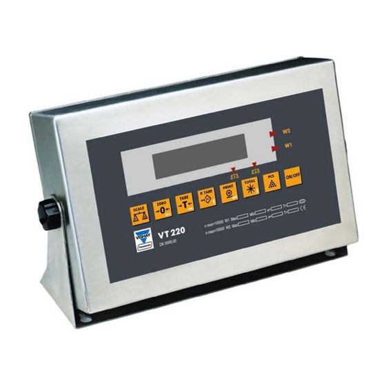
Installation Mounting the Indicator All connections to the instrument are made through the rear panel connectors. Strain- relief clamps should be used. The shield should be connected to the metal frame of the connector. Wall-Mount Model (Stainless Steel Enclosure) 2.2.2 Front and rear views of the unit are shown in Figure 2. -
Page 19: Connecting Load Cells
Installation Connecting Load Cells 2.3 Connecting Load Cells Desktop Model (Aluminum Enclosure) 2.3.1 Use 6 x 0.5mm shielded cable for load cell connections. Connect the load cells according to the diagram below. Load Cell 2 Description COM 2 Analog Output Excitation (-) DB15 Sense (-) -
Page 20: Wall-Mount Model (Stainless Steel)
Installation Connecting Load Cells Wall-Mount Model (Stainless Steel) 2.3.2 Use 6 x 0.5 mm shielded cable for load cell connections. Connect the load cells according to the diagram below. PCB 801 POWER ¯ INPUT ¯ OUT1 OUT2 SGND SHIELD + SIG –... -
Page 21: Serial Connections
Installation Serial Connections 2.4 Serial Connections For RS232C connection, use 3 x 0.34 mm shielded cable. For RS485 connection, use 2 x 0.34 mm shielded twisted pair cable. Printer and PC Cables 2.4.1 Printer DB25 Male Printer DB25 Male Shield Metal Case Max 15m... -
Page 22: Connecting Power
Installation Connecting Power Slave #30 Slave #1 (Up to 30 Slave #2 (VT x00) (VT x00) slaves) (VT x00) … Termination Master Resistor 120R 470R White Network Biasing 150R Resistors Brown Shield 2X0.34mm twisted pair shielded 470R Max cable length: 1000m Chassis Earth Figure 6 –... -
Page 23: Display, Keys And Menus
Display, Keys and Menus The Display 3 Display, Keys and Menus The VT200/220 front panel can be divided into three areas: A six-digit display (LED for VT200, LCD for VT220) that shows weight information, status information, and the names of menus and functions. A keypad with eight keys, allows you to turn the unit on and off, perform the most common functions, and access a function menu with more advanced options. -
Page 24: Status Annunciators
Display, Keys and Menus The Display Status Annunciators 3.1.1 At the bottom and right of the display are several status annunciators. A dot or a light shows up next to these to indicate the current status of the scale or indicator. Status annunciators are often important to understand what is being shown on the display. -
Page 25: Front Panel Keys
Display, Keys and Menus Front Panel Keys ZeRO Automatic or manual zeroing is being performed. Other types of messages may be shown when you perform specific operations, such as editing the tare value or displaying battery status. 3.2 Front Panel Keys The keys on the front panel serve two functions: Performing operations, indicated in black at the center of the key. -
Page 26: Using Keys To Navigate And Enter Information
Display, Keys and Menus The Function Menu Using Keys to Navigate and Enter Information 3.2.2 Description Escape. Cancels the current operation, exits a menu or cancels tare (if active). Next. When editing multiple digits, moves to the next digit. Only press this key once you have finished editing the current (flashing) digit. -
Page 27: Using The Function Menu
Display, Keys and Menus The Function Menu Using the Function Menu 3.3.1 To access a function on the function menu: 1. Press TARE ( ) on the front panel, and keep it pressed for around three seconds. The display shows Fn 00. The left digit should be flashing. 2. - Page 28 Display, Keys and Menus The Function Menu Function Description Refer to Set date, time and serial number. A battery-backed RAM and the Real Time Clock (RTC) option need to be installed to enable setting time. This function depends on the setup parameter 1.6 (1=enabled; 0=disabled). The date format is specified in setup parameter 1.4 (DDMMYY or MMDDYY).
- Page 29 Display, Keys and Menus The Function Menu Function Description Refer to Set print format: 1-line detailed weight. Shows serial number, gross, Section 6.4 tare and net in one line as follows: 00002 01.100kgG 00.100kgT 01.000kgN Set print format: Displayed weight. The weight is shown on the display Section 6.4 (regardless of mode).
- Page 30 Display, Keys and Menus The Function Menu Function Description Refer to Set unit weight for counting, by entering weight. User’s Guide, section 5.3 The display shows XXXXXX. Enter a unit weight , using (P.TARE) to change the current digit, then (TARE) to move to the next digit.
-
Page 31: Setup Menus
Display, Keys and Menus Setup Menus Function Description Refer to Analog output test. Chapter 8 ROM - RAM test. A validity check is performed on system ROM and RAM. Chapter 8 Display segment test. All digits go through 0-9 display routine in Chapter 8 sequence, after which the character set is displayed. -
Page 32: Menu Structure
Display, Keys and Menus Setup Menus Menu Structure 3.4.2 Main menu Submenu Description General scale parameters. SETUP SETUP 1 Serial port 1 parameters. SETUP 2 Serial port 2 parameters. SETUP 3 Tilt Switch parameters. SETUP 4 Setpoint parameters. SETUP 5 Lock keys. -
Page 33: Setup > Setup 2 (Com 1 Settings)
Display, Keys and Menus Setup Menus Par. Description Values Auto power off. Time for the unit to switch off if the scale is zero. 00 - 99 minutes 00=Disabled Number of samples in counting. 5 - 99 SETUP > SETUP 2 (Com 1 Settings) Description Values Print type. -
Page 34: Setup > Setup 3 (Com 2 Settings)
Display, Keys and Menus Setup Menus Description Values Operator print type change (Fn 20- 0=NO 1=YES 30). Data bits/Parity serial channel 1 N8 = 8 Data bits/no parity, 07 = 7 Data bits/odd parity, E7 = 7 Data bits/even parity, 2.11 1 line with date, time and indicated 0=NO... -
Page 35: Setup > Setup 4 (Tilt Switch)
Display, Keys and Menus Setup Menus Data bits serial channel 2. 17 = 7 data bits / even parity 08 = 8 data bits / no parity 18 = 8 data bits / even parity SETUP > SETUP 4 (Tilt Switch) Par. -
Page 36: Setup > Setup 6 (Lock Keys)
Display, Keys and Menus Setup Menus SETUP > SETUP 6 (Lock Keys) Par. Description Values SCALE key. 1=lock 0=unlock ZERO key. 1=lock 0=unlock TARE key 1=lock 0=unlock PRESET key. 1=lock 0=unlock PRINT key. 1=lock 0=unlock TOTAL key. 1=lock 0=unlock PCS key. 1=lock 0=unlock (Reserved for future use) -
Page 37: Acal (Analog Output)
Display, Keys and Menus Setup Menus ACAL (Analog Output) Par. Description Values Standard / custom zero and span. 0 = Standard (20 mA max) 0 specifies that the scale should output 0 mA at zero input and 1 = User defined Zero and 20mA at maximum input (or 0V at zero and 10V at max). -
Page 38: Calibration
Calibration Calibration with Standard Weights (S-CAL) 4 Calibration Before you can calibrate the scale, you must ensure that jumper JP1 is not in the sealed position (see section 4.4). There are two ways to calibrate the VT200/220: Standard weights calibration, in which you record the center of zero, and then place a known weight on the scale and enter its weight (see section 4.1). -
Page 39: Span Calibration
Calibration Electronic Calibration (E-CAL) 5. Press PRINT ( ) to record the zero position. The display counts down for about 10 seconds (50 measurements are taken and an average is calculated). 6. The display should now show 0. If the zero point is not accurate, press ZERO ( and go back to step 3. -
Page 40: Calculating Calibration Values
Calibration Electronic Calibration (E-CAL) Calculating Calibration Values 4.2.1 Consider the following example. A scale has maximum capacity 30/60kg, e=0.010/0.020kg, with 4 load cells of rated capacity 50kg - 2mV each and dead load 1.940kg. The load cell data, as noted in the manufacturer data sheet, is shown in the following table. -
Page 41: Span (Max. Capacity) Calibration
Calibration Storing Calibration Data Span (Max. Capacity) Calibration 4.2.3 To set the span calibration value electronically: 1. Enter the setup menus and use TOTAL ( ) to scroll to the CAL menu. Press PRINT ) to enter the menu. 2. Press PRINT ( ) to enter the E-CAL menu. -
Page 42: Sealing Indicator Enclosure With Stickers
Calibration Locking and Unlocking Calibration Sealing Indicator Enclosure with Stickers 4.4.1 After calibration, you can seal the indicator with two stickers: A non-removable label, to prevent unauthorized opening of the indicator enclosure (Figure 7). A lead wire seal or hard plastic sticker, to prevent unauthorized tampering with the load cell connector (Figure 8). -
Page 43: Figure 10 - D
Calibration Locking and Unlocking Calibration To seal the indicator, desktop (aluminum) model: For the desktop (aluminum) model, refer to Figure 10 below for the non- removable sticker, and to Figure 11 for the lead seal / non-removable sticker. You must apply both stickers. Non- removable sticker... -
Page 44: Securing Load Receptor
Calibration Locking and Unlocking Calibration Lead Seal Figure 11 – Desktop model, sealing with lead seal / non-removable sticker Securing Load Receptor 4.4.2 You can inscribe the serial number of the load receptor as part of the indicator identification label. The load receptor bears the serial number of the indicator on its data plate. -
Page 45: General System Parameters
General System Parameters PAR Menu 5 General System Parameters Two of the VT200/220 setup menus provide access to general system parameters, which affect how the scale operates: The PAR menu contains parameters including the number of display digits, the position of the decimal point, the A/D gain and the zero range (see chapter 5.1). The SETUP 1 submenu, inside the SETUP menu, contains parameters including the date format, totalizer enabling and auto power off (see chapter 5.2). -
Page 46: Par Menu Parameters
General System Parameters PAR Menu PAR Menu Parameters 5.1.2 Par. Description Values Number of display digits. 4, 5, 6 Number of digits after decimal point. Defines the position of the decimal point*. Display resolution*. 1-200 First two digits of full load. 00-99 Digital filter. -
Page 47: Dual-Scale Connecting And Parameter Settings
General System Parameters SETUP 1 (Inside SETUP Menu) Dual-scale Connecting And Parameter Settings 5.1.3 To connect and set up VT200 for dual-scale operations: Set PAR parameters 8.9 to 1, 0.P to 00, and 6.P to a value less than 70 (see 5.1). 4. -
Page 48: Setup 1 Parameters
General System Parameters SETUP 1 (Inside SETUP Menu) To edit parameters in the SETUP 1 menu: 1. The current parameter number is shown on the display. Use PRINT ( ) to scroll to the parameter you need (see the following section for descriptions of parameters). 2. -
Page 49: Serial Communication
Serial Communication Serial Ports Configuration 6 Serial Communication Communication and printer parameters can be set in the SETUP 2 and SETUP 3 submenus of the SETUP menu. 6.1 Serial Ports Configuration VT200/220 has two serial ports, designated port 1 and port 2: Port 1 is an RS232 port. -
Page 50: Setting Port Output Parameters
Serial Communication Setting Port Output Parameters 6.2 Setting Port Output Parameters Setting Port 1 Output 6.2.1 You can use setup parameter 2.t to determine the output for port 1. The parameter accepts the following values: 00 – port disabled. 01, 03, 04, 05, 06, 07, 08, 10, 20 – print formats for printer, equivalent to functions 21, 23, 24, 25, 26, 28, 30, respectively. -
Page 51: Continuous Weight Data Block Composition Leo Format
Serial Communication Output Types Continuous Weight Data Block Composition LEO Format Byte Name Description Weight status Bit 0: 0=Normal 1=No weight display Bit 1: 0=Gross 1=Net Bit 2: 0=No Auto zero 1=Auto zero Bit 3: 0=Within range 1=Out of range Bit 4: 0=No standstill 1=Standstill... -
Page 52: Two-Scale Operation
Serial Communication Output Types Two-Scale Operation When two scales are connected to the indicator, both their weights are transmitted continuously in the format P+123.45 P+678.90CR. In each pair, the first block transmitted is the weight of the first scale, and the second block transmitted is the weight of the second scale. -
Page 53: Data Block Composition
Serial Communication Output Types Data Block Composition Byte Name Description Weight status Bit 0: 0=Normal 1=No weight display Bit 1: 0=Gross 1=Net Bit 2: 0=No Auto zero 1=Auto zero Bit 3: 0=Within range 1=Out of range Bit 4: 0=No standstill 1=Standstill Bit 5: 0=Normal... -
Page 54: Alibi Transmit
Serial Communication Output Types Alibi Transmit 6.3.5 Works with Port1 (RS232). Transmits alibi serial number and gross weight for each transaction, when the PRINT key is pressed. The record is transmitted in the following format: SN 1234 012340 kgG Alibi Mode Commands 6.3.6 When Alibi mode is active (2.t=09), these operations can be executed. -
Page 55: Edp Protocol Output
Serial Communication Output Types The demand character may be programmed through SETUP > SETUP 2, setting 2.c=65-90 (A-Z). A (41h) will generate and transmit the new Alibi number; a (61h) will repeat the last Alibi number (in the case where the message was not received properly). -
Page 56: Edp Data Block Composition
Serial Communication Output Types EDP Data Block Composition Character/s Description STX (02 h) Start of transmission. ASCII (any) ASCII data identical to the data printed. ETX (03 h) End of transmission. Block check character (XORSUM of all data characters STX, ETX inclusive). Remote Printer Output 6.3.8 Works with Port 2 (RS232 or RS485). -
Page 57: Doc # Tm-Vt200/220-En
Serial Communication Output Types Example: BCS2 BCS1 < Ascii ADD (Address) is set in 3.t = 65-90 (A-Z) CheckSum is calculated as the XOR sum of all data characters, ETX excluded. E.g. 02 XOR 41 XOR 3F XOR 30 = 4C (BCS1 = 30+C=3C, BCS2 = 30+4=34) Slave Response STATUS BYTE WEIGHT... -
Page 58: Gross-Tare-Net Weight Transmission
Serial Communication Output Types @ Reset Slave Resets the slave to its power on condition. Master Transmission BCS2 BCS1 Slave Response None. Download Key This is used to download keyboard commands. Use of remote keyboard commands must be enabled: This is done by the setting SETUP3: 3.5=ON. Master Transmission BCS2 BCS1... -
Page 59: Tare Presetting Via Pc
Serial Communication Output Types Byte Name Description Weight status Bit 0: 0=Normal 1=No weight display Bit 1: 0=Gross 1=Net Bit 2: 0=No Auto zero 1=Auto zero Bit 3: 0=Within range 1=Out of range Bit 4: 0=No standstill 1=Standstill Bit 5: 0=Normal 1=Under minimum weighing range Bit 6:... -
Page 60: Standard Print Formats
Serial Communication Standard Print Formats 6.4 Standard Print Formats You can select one of the ten VT200/220’s standard print formats, shown and explained in the table below, using the function menu (functions 21 through 30). Executing the function that corresponds to a print format makes it the current print format. -
Page 61: Custom Print Formats
Serial Communication Custom Print Formats Func. Name of Contents Layout Print Format (in this order) 1-line detailed When net weight is 1234 09260kgG 07940kgT 01320kgN weight showing: Memory serial number, gross weight, tare value and net weight. 1234 07940kgG When gross weight is showing: Memory serial number and gross weight. -
Page 62: Downloading A Custom Print Format
[!016] – current memory serial number. [!017] – net weight. [!042] – current accumulated total. [!098] – unit of weight. Example of Custom Print Format Vishay Transducers WEIGHT <[!014] kg> N: [!016] The above code results in the following printed ticket: Vishay Transducers WEIGHT <12345 kg>... -
Page 63: Doc # Tm-Vt200/220-En
Serial Communication Custom Print Formats 4. Select function 41 or 42 (depending on which memory slot you want to use for the custom print format). Use P.TARE ( ) to edit the current digit and TARE ( ) to move to the next digit. When done, press PRINT ( If you choose the first memory slot (by selecting function 41), and that slot already contains a custom print format to the slot, the indicator downloads a new print format and overwrites the old one. -
Page 64: Outputs And Digital Input
Outputs and Digital Input Specifications 7 Outputs and Digital Input The VT200/220 is able to interface with weighing automation systems, using two optoisolated outputs (digital setpoints) and one digital input. There is also an analog output configuration. The digital outputs (setpoints) are triggered when the scale reads an upper weight threshold, defined by the user. -
Page 65: Connecting Digital Outputs And Tilt Switch
Outputs and Digital Input Connecting Digital Outputs and Tilt Switch 7.2 Connecting Digital Outputs and Tilt Switch Tilt Switch Power Supply Input 1 9-24VDC Fuse Power Supply 24VDC Output 1 Output 2 Digital Outputs Power & Imax=100m Setpoints Connector Figure 12 – Digital output and tilt switch connection diagram 7.3 Setting Thresholds for Digital Setpoints Each setpoint has an upper weight threshold that triggers it. -
Page 66: Configuring Analog Output
Outputs and Digital Input Configuring Analog Output To edit weight thresholds for both setpoints: Press TARE ( ) on the front panel, and keep it pressed for around three seconds. The display shows Fn 00. The left zero flashes. 2. Editing setpoints is function 01, so press (TARE) to move to the second digit. -
Page 67: Connecting Pcb And Setting Jumper
Outputs and Digital Input Configuring Analog Output Connecting PCB and Setting Jumper 7.4.1 In order to use analog output, the option PCB (PCB 761) connected it to the VT200 as follows: In the one side to ST5 socket on the main board and in the other side using the mounting posts/spacers provided to: Stainless steel enclosure –... -
Page 68: Setting Analog Output Parameters
Outputs and Digital Input Configuring Analog Output To set output mode jumper (JP1): Set jumper JP1 to the appropriate position, to define voltage output or current voltage, as shown in the image below. Setting Analog Output Parameters 7.4.2 The output can be set to the standard calibration, where 0 on the weight display is output as 0 mA or 4 mA, and max on the display is output as 20mA. -
Page 69: Calibrating D/A Converter
Outputs and Digital Input Configuring Analog Output Par. Description Values Error output level. Specifies whether scale errors should be 0 = Low (0mA) indicated as a low or high signal. 1 = High (24mA) Current / voltage. This parameter must correspond to the 0 = Current hardware jumper, which defines whether output should be in 1 = Voltage... -
Page 70: Using The Tilt Switch
Outputs and Digital Input Using the Tilt Switch 7.5 Using the Tilt Switch You can set the time delay for the tilt switch function using the setup parameter 4.t. Use this parameter to enter the time delay for display lock in 1/10 seconds. The delay may be between 1 and 90 1/10 seconds (i.e. -
Page 71: Service Operations And Testing
Service Operations and Testing Service Operations 8 Service Operations and Testing 8.1 Service Operations The operations described below are performed by accessing the function menu (pressing the TARE ( ) button for three seconds). For more detailed information on using the function Menu, see section 3.3.1. Setting and Changing Calibration Password (Function 40) 8.1.1 The Personal Identification Number (PIN) is a password that restricts access to the... -
Page 72: Displaying Remaining Battery Capacity (Function 02)
Service Operations and Testing Service Operations To set date, time and serial number: 1. Access the function menu and select function 05. 2. The display shows dAtE briefly, and then the date (in either of the formats DDMMYY or MMDDYY, depending on setup parameter 1.4). Edit the date, using P.TARE ( ) to change the current digit, and TARE ( ) to move to the next digit. -
Page 73: Viewing A/D Count (Function 81)
Service Operations and Testing Testing the Indicator Viewing A/D Count (Function 81) 8.1.6 To view the A/D count: Access the function menu and select function 81. The indicator shows the analog- to-digital converter internal count. Press ESC ( ) to exit. View Software Version Number and Date (Function 82) 8.1.7 To view the number and date of the current software version:... -
Page 74: Testing The Keypad And Display (Function 90, 91)
Service Operations and Testing Testing the Indicator To test ROM/RAM integrity: 1. Access the function menu and select function 86. 2. One of the following messages are displayed: Err 01 – indicates that ROM data is corrupted. Err 02 – indicates that RAM data is corrupted. PASS –... -
Page 75: Testing The Print Buffer (Function 94)
Service Operations and Testing Testing the Indicator 4. Press PCS ( ) to toggle output 2 on and off. When it is on, the data sent should be displayed in the sixth digit. If the output connects to another device, check if the signal was received. -
Page 76: Troubleshooting
Troubleshooting Errors, Causes and Remedies 9 Troubleshooting The indicator has no serviceable parts. Authorized technicians may: Respond to errors shown on the display (see chapter 9.1). Check load cell connections (see chapter 9.2). Check the power supply (see chapter 9.3). Check the digital outputs (see chapter 9.4). - Page 77 Troubleshooting Errors, Causes and Remedies Error code Possible cause Actions to be taken Err 30 The host PC is not connected, or the Make sure the computer is connected, and communication link failed. press PRINT ( ) to retry. If there is some problem with the computer, but you would like to use the indicator anyway, press ZERO (...
-
Page 78: Checking Load Cell Connection
Troubleshooting Checking Load Cell Connection 9.2 Checking Load Cell Connection If there appears to be a problem with the load cell connection: Check input and output resistance. Check resistance between any terminal and shield. Check load cell connection and cable. 9.3 Checking Power Supply If the unit does not turn on: Check 9-15VDC power supply. -
Page 79: Appendix A: Technical Drawings
Appendix A: Technical Drawings i. System Block Diagram Appendix A: Technical Drawings i. System Block Diagram RS232 (ST8) J1 32KB EEPROM & R.T.C Watchdog RS232 Driver PCB 750 Max 10 X 350Ω Load Cells (ST7) J2 Analog to J3 (ST2) Digital 89C51RD Conversion... - Page 80 Appendix A: Technical Drawings ii. Rear Panel Connections (Desktop Model) ii. Rear Panel Connections (Desktop Model) Load Cell 2 COM 2 Analog Output DB15 DB9 fem fem/male Load Cell 1 COM 1 DB9 male DB15 fem & S COM 2 COM 1 2 (DB15 F) OWER...
- Page 81 Appendix A: Technical Drawings iii. Terminal Connections (Wall-Mount Model) iii. Terminal Connections (Wall-Mount Model) PCB 801 POWER PCB 715 ¯ (VT200) INPUT PCB 716 (VT220) ¯ OUT1 OUT2 SGND Cal. Lock SHIELD + SIG – SIG + EX SHLD + SEN +SIG - SEN –SIG...
- Page 82 Appendix A: Technical Drawings iv. Cabling Diagram iv. Cabling Diagram Slave #1 (Up to 30 Slave #30 Slave #2 (VT x00) slaves) (VT x00) (VT x00) … Master Termination Resistor 120R 470R White Network Biasing 150R Resistors Brown Shield 2X0.34mm twisted pair shielded 470R Max cable length: 1000m...
- Page 83 Appendix A: Technical Drawings v. Printed Circuit Boards v. Printed Circuit Boards PCB 761 ANALOG OUTPUT PCB 439 RS485 PCB 801 MAIN BOARD PCB 765 ANALOG INPUT VT200/220 Technical Manual, Rev 1.00.01 Doc # TM-VT200/220-EN...
-
Page 84: Contacting Vishay Transducers
FAX: +972-9-863-8800 E-MAIL: vt.il@vishaymg.com Asia Vishay Transducers Taiwan (Asia except Vishay Transducers China China) No. 5 Binguan Nan Dao Youyi Rd., Hexi District, 15 Fl, No. 86, Sec. 1 Sintai 5 Tianjin China, Code 300061 Shijr City, Taipei, 22102, Taiwan R.O.C...
Need help?
Do you have a question about the VT 200 and is the answer not in the manual?
Questions and answers