
Related Manuals for EarthLinked AVS-0030-A


Summary of Contents for EarthLinked AVS-0030-A
- Page 1 Classic Series SD (H) Geothermal Heating and Cooling System Quick-Start Instructions SD-410-QS (H) (06/15) Copyright 2015 Earthlinked Technologies, Inc.
- Page 2 Table of Contents Model Nomenclature .......................... 5 Safety ..............................6 Equipment Manuals ........................... 6 Installation ............................7 Component Matching ........................7 Compressor Unit Placement ......................8 Refrigeration ..........................9 System Applications and Electrical .................... 13 Plumbing ............................ 21 Antifreeze Protection ........................23 Internal Heat Recovery System ....................
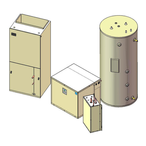
- Page 3 List of Figures Figure 1. Matching Component Model Numbers .................. 7 Figure 2. General Layout of System Components ................8 Figure 3. Compressor Unit Bracket Installation ..................9 Figure 4. Compressor Unit Clearance ....................9 Figure 5. SD(H) Connections ......................10 Figure 6.
- Page 4 Figure 32. Suction Pressure and Temperature Measurements (SC System shown) ......45 Figure 33. Many Bubbles-Inline Sight Glass ..................46 Figure 34. Clear-Inline Sight Glass ....................46 Figure 35. Trickle of Bubbles-Inline Sight Glass ................. 46 Figure 36. Minimum Suction and Discharge Pressures ..............47 Figure 37.
-
Page 5: Model Nomenclature
Earthlinked Technologies. Installation and service must be made in accordance with the instructions set forth in this manual. Failure to provide installation and service by an ETI authorized installer in a manner consistent with this manual will void and nullify the limited warranty coverage for the system. -
Page 6: Safety
Equipment Manuals The following is a listing of the equipment installation manuals that are provided with each component ® specified for this EarthLinked system. IMPORTANT! Read and follow all installation instructions in these manuals, ®... -
Page 7: Installation
Figure 1, to ensure that all components of the system match. HEAT/COOL Applications Air Handler Compress. Hydronic Water Hybrid Cooling Cased Coil TXV Kit Model Earth Loop Unit Module Module Var. Speed -024 AVS-0030-A CCS-0036-A TXV-2430CE HWM-024C -024-C HCM-1836C -030 AVS-0036-A CCS-0036-A TXV-2430CE HWM-030C -030-C -036 AVS-0048-A... -
Page 8: Compressor Unit Placement
Compressor Unit Placement ® EarthLinked compressor units may be located inside or outside. If outside, place compressor unit on a standard HVAC outdoor unit pad. If inside, place it on a level, hard surface. If the compressor unit is to be fastened down, see Figure 3 for bracket installation. -
Page 9: Refrigeration
Figure 3. Compressor Unit Bracket Installation Figure 4. Compressor Unit Clearance ® Placement instructions for other pieces of equipment that make up the EarthLinked System are included with those pieces of equipment and are listed in this manual under Equipment Manuals. -
Page 10: Figure 5. Sd(H) Connections
COMPRESSOR UNIT MODEL TYPE OF CONNECTION SIZE, INCHES PORT FUNCTION CONNECTION -024 -030 -036 -042 -048 -054 -060 1-1/4” Hole Electrical, Power 7/8” Hole Electrical, Control AH/CC Liquid Braze HWM Vapor Braze EL Liquid* Braze Anode Socket EL Vapor* Braze AH/CC Vapor Braze Plugged... - Page 11 Compressor units are shipped from the factory with a low pressure nitrogen holding charge. Carefully relieve the holding charge when the compressor unit is being prepared to connect refrigerant system piping. Caution! This compressor unit is equipped with POE lubricant. POE lubricant absorbs significant amounts of moisture from the air very rapidly.
-
Page 12: Figure 6. Line Set Sizes
The compressor unit package contains a service valve kit and an adapter kit. The two service valves are to be installed on the earth loop vapor and liquid connections of the compressor unit, using the adapters to right-size to the proper earth loop line set. Installation of the service valves will provide isolation of the earth loop system from the compressor unit and provide easy access to the refrigerant system. -
Page 13: System Applications And Electrical
System Applications and Electrical The SD(H) compressor unit electrical box major components and electric data for all compressor sizes are shown in Figure 7. The SureStart Module is a factory installed component that (1) reduces compressor starting current and (2) reduces compressor starting torque, thus reducing stress on the compressor at start-up. The Earth Loop Protection Control System, comprised of the EPS Power Supply, EPS Module and EPS Fuse is in the contained within the electric box. -
Page 14: Figure 7. Sd(H) Electric Box Components & Electrical Data
Voltage Compressor Compressor Voltage/Phase/ Unit Model Model Min. Max. -024-1C ZP25K6E-PFV 230-1-60 72.5 15.0 18.0 -024-2C ZP25K63-TF5 230-3-60 61.4 12.0 -030-1C ZP31K5E-PFV 230-1-60 78.0 18.6 23.0 -030-2C ZP31K5E-TF5 230-3-60 73.0 11.6 14.0 -036-1C ZP38K5E-PFV 230-1-60 109.0 22.1 27.0 -036-2C ZP38K5E-TP5 230-3-60 83.1 15.1... -
Page 15: Figure 8A. Sd(H) Compressor Unit Electrical Ladder Diagram, 230-1-60
Figure 8a. SD(H) Compressor Unit Electrical Ladder Diagram, 230-1-60 SD-410-QS (H) (06/15) Page 15... -
Page 16: Figure 8B. Sd(H) Compressor Unit Electrical Schematic Diagram, 230-1-60
Figure 8b. SD(H) Compressor Unit Electrical Schematic Diagram, 230-1-60 SD-410-QS (H) (06/15) Page 16... -
Page 17: Figure 9A. Sd(H) Compressor Unit Electrical Ladder Diagram, 230-3-60
Figure 9a. SD(H) Compressor Unit Electrical Ladder Diagram, 230-3-60 SD-410-QS (H) (06/15) Page 17... -
Page 18: Figure 9B. Sd(H) Compressor Unit Electrical Schematic Diagram, 230-3-60
Figure 9b. SD(H) Compressor Unit Electrical Schematic Diagram, 230-3-60 SD-410-QS (H) (06/15) Page 18... -
Page 19: Figure 10A. Sd(H) Air Heating/Cooling, Hydronic Heating And Water Heating Application
Figure 10a. SD(H) Air Heating/Cooling, Hydronic Heating and Water Heating Application SD-410-QS (H) (06/15) Page 19... -
Page 20: Figure 10B. Sd(H) Air Heating/Cooling, Hydronic Heating And Water Heating Field Wiring Diagram
Figure 10b. SD(H) Air Heating/Cooling, Hydronic Heating and Water Heating Field Wiring Diagram SD-410-QS (H) (06/15) Page 20... -
Page 21: Plumbing
Plumbing A typical primary hydronic plumbing circuit for an SD(H) system is illustrated in Figure 11. Figure 11. Typical SD(H) Primary Hydronic Circuit Plumbing The components are as follows: 1. Flowmeter: Model ETI-A1-116000-1 hydronic water/antifreeze solution flowmeter is available from ETI and is field calibrated for the specific antifreeze mixture. The kit includes calibration equipment. - Page 22 4. Storage Water Heater: The GSTE Series storage water heaters are available from ETI in 60, ® 80 and 119 US Gallon capacities, and are designed for use with the EarthLinked geothermal systems. They are equipped with a 4.5 kW supplemental heater which satisfies the ETI requirement for a minimum of 20% supplemental heat.
-
Page 23: Antifreeze Protection
SOLUTION PROTECTION IN EARTHLINKED RADIANT PANEL HYDRONIC HEATING AND/OR COOLING SYSTEMS AT THE TIME OF ® SYSTEM START-UP WILL VOID THE EARTHLINKED LIMITED WARRANTY FOR HEATING AND COOLING SYSTEMS. Propylene-glycol antifreeze solution with an inhibitor is the type of antifreeze solution required for ®... - Page 24 General guidelines for introducing propylene glycol into the water circulating system follow. The manufacturer’s specific instructions and industry standards always take precedence when introducing propylene-glycol to the system. Calculate the quantity of inhibited propylene-glycol (fluid) required to achieve the desired results.
-
Page 25: Internal Heat Recovery System
Internal Heat Recovery System The SD(H) Compressor Unit has a built-in Heat Recovery System for the purpose of providing supplemental water heating during heating and/or cooling operation. The Heat Recovery System does not replace the standard storage water heater sized for the application. Use of the Heat Recovery System to heat water in the heating season will increase the heating load on the space heating equipment by 2,000 BTUH for each adult and teenager occupant. -
Page 26: Figure 13A. Gste Storage Water Heater - Service Connections
Figure 13a. GSTE Storage Water Heater - Service Connections Figure 13b. GSTE Storage Water Heater – Tank Top View SD-410-QS (H) (06/15) Page 26... - Page 27 The SD(H) compressor unit desuperheater contains a water high temperature control. It is factory set to 140°F. The desuperheater also contains a refrigerant low temperature limit switch, which is factory set to 125°F. Also, a freeze protection control is designed to operate the circulating pump when water temperature drops to 40°F, in order to provide water circulation independent of compressor operation.
-
Page 28: Earth Loop Protection System
WARNING! ® All power of the EarthLinked System is to be shut OFF at the disconnect while field wiring the Earth Loop Protection System. Failure to do so may result in serious injury or death, or equipment or property damage. -
Page 29: Figure 15. Disassembled Plug Connector
Figure 15. Disassembled Plug Connector SD-410-QS (H) (06/15) Page 29... -
Page 30: Figure 16. Anode Wire Insertion
Strip the insulation from the multi-strand anode wire back approximately ¾ inch from the end and, while keeping the strands together, push the anode wire through the gland nut, gland cage, gland and plug body as shown in Figure 16. Loosen one of the two screw terminals on the plug insert to receive all of the strands of anode wire on one terminal. -
Page 31: Figure 17. Install The Plug Insert
Figure 17. Install the Plug Insert Slide the gland forward on the anode wire until it is firmly seated in the plug body as shown in Figure 18. Next, slide the gland cage over the gland, and slide the gland nut firmly against the gland cage, with the gland nut against the plug body. -
Page 32: Figure 19. Secure The Anode Wire
Once the gland nut has been hand tightened into the plug body, use two adjustable wrenches to further tighten the gland nut until it is snug in the plug body as shown in Figure 19 and the anode wire is held firmly in the plug body and will not slip out. Do not over-tighten the gland nut! Figure 19. -
Page 33: Eps Operation And Service
EPS Operation and Service Reference Figure 21 for the EPS components in the compressor unit electric box. Figure 21. Electric Box with EPS Components With power ON, and viewing the EPS Module in the compressor unit electric box, the EPS green light should be illuminated, indicating there is power to the EPS system. -
Page 34: Current Verification
Current Verification If it is necessary to verify the current flow through the EPS system, it can be checked with a digital DC ammeter set on the Milliampere scale. The correct electrical currents for nominal system capacities are listed in Figure 22. Nominal System Capacity, Tons Current Rating 1.5 thru 2.5... -
Page 35: System Start-Up
Evacuation CAUTION! During the Evacuation and Initial Charging processes, be sure that ALL ® power to the EarthLinked System is OFF. This includes the compressor unit, air handler and all other electrically powered system components. Prior to system start-up, evacuation of the system is accomplished through the compressor unit. All of the refrigerant containing components in the compressor unit are illustrated in Figures 24 and 25. -
Page 36: Figure 25. Sd(H) Piping
Figure 25. SD(H) Piping Refer to Figure 26 and the following procedure: 1. Carefully vent any pressurized charge from the compressor and system.. 2. After venting the pressurized system, connect the Gage Block and Hoses as shown in Figure 26. LP and HP valves are fully open. Both Service Valves are fully opened. 3. -
Page 37: Figure 26. Evacuation Of Sd(H) System
Figure 26. Evacuation of SD(H) System IMPORTANT! DO NOT ENERGIZE THE COMPRESSOR WHILE THE SYSTEM IS UNDER VACUUM. THIS WILL CAUSE DAMAGE TO THE COMPRESSOR. 4. Initiate the system evacuation. Evacuate the system down to 400 MICRONS as read on the digital micron gage. -
Page 38: Initial Charge
Initial Charge 1. Close the LP and HP valves on the gage block. Disconnect and isolate the vacuum pump and digital micron gage. Connect the refrigerant container (on the scale) to the gage block utility hose as shown in Figure 27. WARNING! Inhalation of high concentrations of refrigerant gas vapor is harmful and may cause heart irregularities or death. -
Page 39: Figure 27. Initial Charge Of Sd(H) System
Figure 27. Initial Charge of SD(H) System 2. Open the refrigerant container valve and inject liquid refrigerant into the initial charging port as shown in Figure 27. 3. Charge with liquid refrigerant until 3 pounds of refrigerant per ton of system capacity, has entered the system. -
Page 40: Final Charge
Final Charge It is critical to control the conditions under which the compressor unit operates while final charging the system. Final charging must be done in HEAT mode. IMPORTANT! For this SD(H) Model, final charging should be done using the AIR HANDLER in HEAT MODE. -
Page 41: Figure 29. Charge At Bottom Sight Glass
1. Re-connect the red HP hose, after purging with a trickle of refrigerant, (from the initial charging port in Figure 27) to the access port as shown in Figure 28. Continue measuring the refrigerant charge weight as shown in Figure 28. 2. -
Page 42: Figure 30. Air System Performance Parameters
For Air Systems: In Figure 30, locate the evaporating temperature on the horizontal axis. The corresponding condensing temperature reading should fall between the upper and lower parallel lines in Figure 30. The temperature profile in Figure 30 is valid for the air handler systems with an air flow of 400CFM per Ton. -
Page 43: Cool Mode Start-Up
Figure 31. Hydronic System Performance Parameters 8. Check the suction saturation temperature to verify that it is within ±3°F for the measured suction pressure. The suction temperature should be approximately 15 to 20°F lower than the local earth temperature. Cool Mode Start-Up IMPORTANT! Be sure the return air to the air handler is maintained in the range of 70ºF to 80ºF. - Page 44 These following steps describe the procedure for system start-up in the cooling mode. This is illustrated in the process flow chart, Figure 38. Be sure the cooling mode for the system is enabled. 1. Close the HP valve on the gage block. Turn the system on in COOL mode, monitor the suction pressure, and wait for it to stabilize.
-
Page 45: Figure 32. Suction Pressure And Temperature Measurements (Sc System Shown)
Figure 32. Suction Pressure and Temperature Measurements (SC System shown) SD-410-QS (H) (06/15) Page 45... -
Page 46: Figure 33. Many Bubbles-Inline Sight Glass
Figure 33. Many Bubbles-Inline Sight Glass 6. When suction pressure reaches 120 psig, observe the INLINE sight glass. If it is either clear as shown in Figure 34, or has a trickle of bubbles as shown in Figure 35, no additional refrigerant charge is required. Go to step 10. Figure 34. -
Page 47: Figure 36. Minimum Suction And Discharge Pressures
9. If there are many bubbles in the INLINE sight glass, as shown in Figure 33, additional refrigerant is required. Repeat step 7 until the INLINE sight glass clears or has a trickle of bubbles as shown in Figure 34 or 35, respectively, but DO NOT ADD MORE THAN THE FOLLOWING AMOUNTS OF REFRIGERANT TO THE SYSTEM DURING THIS PROCESS: Nominal System Tonnage... -
Page 48: Figure 37. Pressure-Temperature For R-410A
SATURATION SUCTION SATURATION SUCTION TEMPERATURE PRESSURE TEMPERATURE PRESSURE (°F) (psig) (°F) (psig) 26.1 199.2 30.8 216.1 35.9 234.0 41.5 253.0 47.5 273.0 54.1 294.1 61.2 316.4 68.8 339.9 77.1 364.6 86.0 390.5 95.5 417.7 105.7 446.3 116.6 476.3 128.3 507.6 140.8 540.5 154.1... -
Page 49: Figure 38. Cooling Mode Start-Up
Figure 38. Cooling Mode Start-Up SD-410-QS (H) (06/15) Page 49... -
Page 50: Troubleshooting
IMPORTANT! EarthLinked® Refrigerant System Safety Switches EarthLinked® compressor units are equipped with the following three safety switches that will turn the compressor off if the following limits are exceeded. High Pressure Switch: Located between the compressor discharge port and the reversing valve, the cut-out pressure is 600 psig. -
Page 51: Figure 39. Compressor Unit Voltage Information
Figure 39. Compressor Unit Voltage Information The following compressor checklist is provided to analyze the compressor and determine if it is operating properly or if it is faulty: 1. Electrical Service Panel – turn power off. a. Check circuit connections for tightness b. -
Page 52: Figure 40. Compressor Motor Circuit Testing
7. Motor Circuit Testing Using a digital volt-ohmmeter (VOM), measure the resistance across the compressor windings as shown in Figure 40. The power leads to the compressor must be disconnected before taking an electrical measurement. A good rule of thumb for single phase compressors is that start winding resistance (R ) is 3 to 5 times greater than run winding resistance (R... -
Page 53: Figure 41. Compressor Motor Grounded Winding Test
8. Grounded Windings Test the compressor motor for a grounded winding. The check should be made using an ohmmeter capable of measuring very high resistance on a VOM. The resistance between windings and the housing is one million to three million ohms for an ungrounded winding. -
Page 54: System
System Problem / Likely Cause(s) Correction Symptom 1. Adjust thermostat settings. / Replace 1. Thermostat fault. thermostat. A. System does not run. 2. Power supply problem (AHU / 2. Check power supply for adequate compressor unit). phase and voltage. Check wiring to system and external breakers or fuses. - Page 55 C. System blows 4. Excessively high or low supply 4. Note voltage range limitations specific fuses or trips to the compressor. voltage or phase loss (3 only). circuit breaker 5. Faulty run capacitor or soft start 5. Replace as necessary. (con’t) components.
- Page 56 7. Refrigerant undercharged. 7. Check for refrigerant level in G. Uncomfortable ACC.(Heating mode only) temperature. Repair leak, evacuate and recharge the (Not enough system. Check In-line sight glass in heat/cold air) cooling mode. (cont’d) 8. Restriction in refrigerant circuit. 8. Check for blockage or restriction, especially in Liquid Flow Control.
-
Page 57: Commissioning Document
Commissioning Document The document that follows (LIT-170) enables verification and documentation of system component model numbers, location of underground system components and system performance for air and hydronic heating and cooling. SD-410-QS (H) (06/15) Page 57... - Page 58 SD-410-QS (H) (06/15) Page 58...
- Page 59 SD-410-QS (H) (06/15) Page 59...
- Page 60 SD-410-QS (H) (06/15) Page 60...
- Page 61 SD-410-QS (H) (06/15) Page 61...
- Page 62 SD-410-QS (H) (06/15) Page 62...
- Page 63 SD-410-QS (H) (06/15) Page 63...
-
Page 64: Tools And Equipment
Tools and Equipment The purpose of the following list is to highlight key pieces of equipment, tools and materials necessary ® for the installation, maintenance and servicing of EarthLinked Heating and Cooling System HVAC (above ground) equipment. The professional HVAC technician is expected to have a compliment of standard tools for the general servicing of refrigeration equipment. -
Page 65: Triple Evacuation
1. Attach an electronic micron gage to the system. The best place is as far from the vacuum port ® as possible, which would be the access port on a service valve on the EarthLinked compressor unit. 2. Let the vacuum pump run until the micron gage reaches 1500 microns.
Need help?
Do you have a question about the AVS-0030-A and is the answer not in the manual?
Questions and answers