
Subscribe to Our Youtube Channel
Related Manuals for EarthLinked HWM-18B


Summary of Contents for EarthLinked HWM-18B
- Page 1 ® EarthLinked Hydronic Water Module Installation, Operation & Maintenance Manual R-407C Heat/Cool and Cool Only Systems HWM-407CH-IOM (09/13) Copyright 2013 Earthlinked Technologies, Inc...
- Page 2 Installation and service must be made in accordance with the instructions set forth in this manual and the current EarthLinked Heating and Cooling Installation, Operation and Maintenance Manual. Failure to provide installation and service by an authorized, trained installer in a manner consistent with the subject manuals will nullify the limited warranty coverage for the system.
- Page 3 Table of Contents 1. Inspection/Pre-Installation ......................5 A. Inspection ........................... 5 B. Pre-Installation ........................6 2. General System Layout ......................7 3. Applications ..........................8 4. The Primary Circuit ........................ 10 A. Plumbing .......................... 10 B. Antifreeze Protection ......................11 C.
- Page 4 Figure 3. Typical Chilled Water Cooling and Radiant Panel Hydronic Heating System ...... 8 Figure 4. Typical Chilled Water Cooling System ................9 ® Figure 5. Primary Circuit for EarthLinked System with HWM ............10 Figure 6. Typical HWM Primary Circuit Plumbing ................11 Figure 7.
-
Page 5: Inspection/Pre-Installation
Upon receipt of the equipment, carefully check the shipment against the bill of lading. ® Reference EarthLinked matching system component model numbers in Figure 1. Make sure all units have been received and model numbers are the same as those ordered. -
Page 6: B. Pre-Installation
Examine all equipment before installing. B. Pre-Installation ® Prior to installing the Hydronic Water Module and other EarthLinked space heating and cooling system above-ground components, you will need tools and equipment listed in Section 8 to properly install the system. -
Page 7: General System Layout
2. General System Layout ® Guidelines for the general layout of the Hydronic Water Module and other EarthLinked system components are shown in Figure 2. Figure 2. General System Layout HWM-407CH-IOM (09/13) Page 7... -
Page 8: Applications
3. Applications A typical application of the Hydronic Water Module to a chilled water cooling and radiant panel hydronic heating system is illustrated in Figures 3. Figure 3. Typical Chilled Water Cooling and Radiant Panel Hydronic Heating System HWM-407CH-IOM (09/13) Page 8... -
Page 9: Figure 4. Typical Chilled Water Cooling System
A typical application of the Hydronic Water Module to a chilled water cooling system is illustrated in Figures 4. Figure 4. Typical Chilled Water Cooling System HWM-407CH-IOM (09/13) Page 9... -
Page 10: The Primary Circuit
A. Plumbing The primary circuit in a typical HWM installation is shown in Figure 5. ® Figure 5. Primary Circuit for EarthLinked System with HWM The Hydronic Water Module primary circuit water solution plumbing must be installed consistent with local codes and industry practice. At a minimum, the HWM should have the fittings as shown in Figure 6. -
Page 11: B. Antifreeze Protection
The antifreeze ® protection is provided by the installer prior to the EarthLinked system start-up. HWM-407CH-IOM (09/13) -
Page 12: Figure 7. Propylene Glycol Freeze Protection Table
Propylene-glycol antifreeze solution with an inhibitor is the type of antifreeze solution ® required for Earthlinked products utilized in radiant panel hydronic heating and/or chilled water cooling systems. These systems shall be freeze protected consistent with the application-specific minimum temperature as shown in the table below. Propylene-glycol antifreeze solutions should always be in the range of 20% to 50% by volume, as indicated in Figure 7. -
Page 13: C. Water Quality
• Drain some water from the system to provide enough volume for the calculated amount of fluid. • Add the correct amount of fluid and any water needed to completely refill the system, allowing for liquid expansion due to operating temperature. •... -
Page 14: D. Storage Water Heater Sizing And Connections
D. Storage Water Heater Sizing and Connections ® Storage water heaters are necessary with EarthLinked radiant panel hydronic heating and chilled water cooling systems, as illustrated in Figures 3, 5 and 6. ETI Models 60, 80 or 119 GSTE storage water heaters are configured specifically for hydronic heating and chilled water cooling and meet all requirements for these applications. -
Page 15: E. Circulating Pump, Piping, Strainer And Flowmeter
Figure 8c. Typical HWM Piping Illustration E. Circulating Pump, Piping, Strainer and Flowmeter The HWM system primary circuit piping arrangements for chilled water (to air) cooling and radiant panel hydronic heating are illustrated in Figures 3 and 4. HWM-407CH-IOM (09/13) Page 15... -
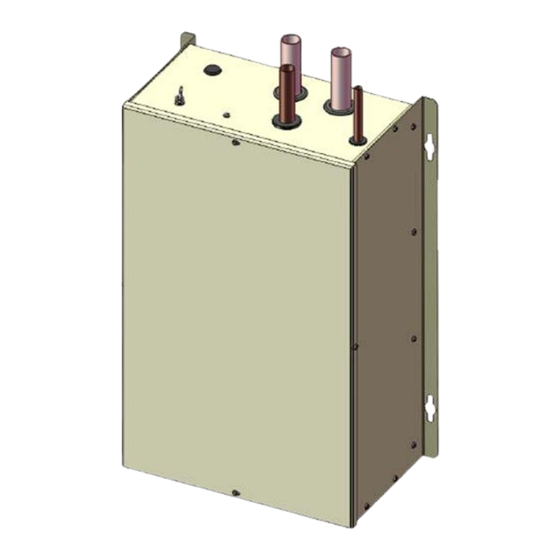
Page 16: Figure 9. Hydronic Water Module (Hwm)
The Hydronic Water Module physical dimensions as well as water solution piping connections are illustrated in Figure 9. Figure 9. Hydronic Water Module (HWM) HWM-407CH-IOM (09/13) Page 16... -
Page 17: F. Refrigerant Piping
Figure 10a lists the minimum nominal Type L hard copper pipe and fitting sizes, and the strainer required for the primary circuit between the hot water module (HWM) and the storage water heater. Minimum Nominal Type L Compressor Unit Size ETI Strainer HWM Models Hard Copper Pipe and... -
Page 18: Controls And Electrical
5. Controls and Electrical A. Hydronic Heating and Chilled Water Cooling Figures 3 and 5 illustrate a typical hydronic heating and chilled water cooling primary circuit configurations. The use of a three-way valve is shown in these illustrations. For heating, the valve is normally open with the flow from the HWM directed DOWNWARD providing heated water to the storage water heater. -
Page 19: B. Chilled Water Cooling
Figure 10c. (Part 2 of 2) Electrical Field Wiring – Hydronic Heating and Chilled Water Cooling (HWM) B. Chilled Water Cooling The electrical field wiring for the CWK-1872 chilled water temperature controller is illustrated in Figure 10d (Part 1 of 2) and 10d (Part 2 of 2). HWM-407CH-IOM (09/13) Page 19... -
Page 20: Figure 10D. (Part 1 Of 2) Electrical Field Wiring – Chilled Water Cooling (Hwm)
Figure 10d. (Part 1 of 2) Electrical Field Wiring – Chilled Water Cooling (HWM) Figure 10d. (Part 2 of 2) Electrical Field Wiring – Chilled Water Cooling (HWM) HWM-407CH-IOM (09/13) Page 20... -
Page 21: C. Hwm Freeze Protection Thermostat
C. HWM Freeze Protection Thermostat 1. The freeze protection thermostat is factory installed. The thermostat wiring must be connected when the HWM is installed. Run the wire through the electrical port in the top panel of the Hydronic Water Module cabinet. After attaching the wire to the switch terminals, run it into the Compressor Unit (using a control wiring port), in accordance with applicable electrical codes. -
Page 22: Start-Up
6. Start-Up The following conditions must be met before starting the HWM: • The toggle switch on the HWM cabinet must be “OFF”. • The system has been charged according to instructions. • Heating elements in the hot water storage tank are “OFF”. •... -
Page 23: Figure 11. Maximum Operating Conditions (R-407C)
Figure 11. Maximum Operating Conditions (R-407C) 6. As appropriate, adjust chilled water controller to a temperature cut out point which is approximately 5°F above the desired chilled water leaving temperature HWM-407CH-IOM (09/13) Page 23... -
Page 24: Heat Exchanger Maintenance
7. Heat Exchanger Maintenance A compact brazed heat exchanger is utilized in the Hydronic Water Module. The water flow rate designed into each of these heat exchangers is 2 or more gallons per minute per ton of nominal system capacity. The acceptable water flow rate range for each system is shown in Figure 12. -
Page 25: Figure 13. Minimum Heat Exchanger Propylene Glycol/Water Solution Flow Rates
Minimum Propylene Glycol/Water Solution Flow Compressor Unit Rates, GPM Size/Capacity Model (BTUH) 20% PG 30% PG 40% PG 50% PG -018 (18,000) -18B -024 (24,000) -24B -030 (30,000) -30B -036 (36,000) -36B -042 (42,000) -42B -048 (48,000) -48B -060 (60,000) -60B 10.3 10.7... -
Page 26: Figure 14. Hwm Heat Exchanger Cleaning Set-Up
Figure 14. HWM Heat Exchanger Cleaning Set-up Disconnect power from HWM and be sure pump is off. Mix heat exchanger cleaning solution in a 55 gallon drum can be sealed and disposed of in accordance with local and federal chemical waste regulations, when the cleaning process is completed. - Page 27 Mix 1 gallon of concentrated liquid ice machine cleaner per 15 gallons of water in a 55 gallon drum as shown in Figure 14. Connect the 3/4” ID x 15’ heavy duty hose to the hose bibb on gate valve (3) and return to the container holding the cleaning solution.
-
Page 28: Tools And Equipment
8. Tools and Equipment The purpose of the following list is to highlight key pieces of equipment, tools and materials necessary for the installation, maintenance and servicing of EarthLinked® Heating and Cooling System HVAC (above ground) equipment. The professional HVAC technician is expected to have a compliment of standard tools for the general servicing of refrigeration equipment. -
Page 29: Index
Index Circulating ...........................15, 18, 27 Compressor ......................14, 17, 22, 24, 25 Connection ............................ 14 Connections ......................6, 14, 16, 17, 22 Controls ............................18 Flow Meter ..........................17, 28 Flow Rate ..........................24, 25 Manifold ........................... 22, 28 Model ........................5, 14, 17, 24, 25 Piping ..........................15, 16, 17 Pump ........................
Need help?
Do you have a question about the HWM-18B and is the answer not in the manual?
Questions and answers